
A transformer is one of the most efficient machines ever built — large power transformers routinely exceed 98% efficiency. Yet no transformer is perfect. Every unit converts a small fraction of the power passing through it into heat, hum, and vibration instead of useful output. These wasted watts are called transformer losses, and understanding them is essential for selecting, sizing, testing, and troubleshooting transformers.
Losses fall into two great families: iron losses (also called core losses), which occur in the magnetic core whenever the transformer is energized, and copper losses (winding losses), which occur in the windings whenever load current flows. Add a few smaller strays, and you have the complete picture. In this guide we will break down each loss, show you the formulas, work through a real efficiency calculation, and explain how engineers keep losses to a minimum.
If you are new to the machine itself, start with our guide to how a transformer works — then come back here for the losses in detail.
Why No Transformer Is 100% Efficient
An ideal transformer would transfer every watt from primary to secondary. Real transformers lose energy through two unavoidable physics facts:
- The alternating magnetic flux in the core constantly magnetizes and demagnetizes the iron — and that process dissipates energy as heat.
- The windings are made of copper (or aluminum), which has electrical resistance — and current through resistance always produces I²R heating.
Because of this, a transformer’s output power is always slightly less than its input power:
Total losses = Iron losses + Copper losses + stray losses
Efficiency is then simply:
η = (Output power ÷ Input power) × 100 = [Output ÷ (Output + Losses)] × 100
Iron Losses (Core Losses): Present Whenever Energized
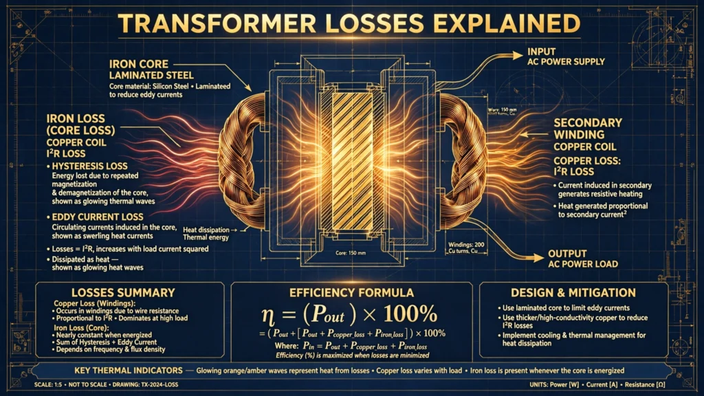
Iron losses occur in the laminated steel core and depend on the supply voltage and frequency — not on the load. A transformer humming away on no-load, secondary open-circuited, is still burning iron losses. They have two components:
Hysteresis Loss
Each AC cycle forces the core’s magnetic domains to flip direction — magnetize, demagnetize, remagnetize in reverse, 50 or 60 times per second. Flipping domains takes energy, dissipated as heat. Hysteresis loss depends on the core material’s magnetic properties, the maximum flux density, and the frequency:
Ph ∝ f × Bmax^n (Steinmetz equation, n ≈ 1.6–2 for silicon steel)
This is why transformer cores use grain-oriented silicon steel — its narrow hysteresis loop wastes far less energy per cycle than ordinary iron.
Eddy Current Loss
The alternating flux also induces circulating currents — eddy currents — inside the core steel itself, which heat it up like a tiny induction furnace. Eddy current loss follows:
Pe ∝ f² × Bmax² × t²
where t is the thickness of the steel. Notice the t² term: halving lamination thickness cuts eddy loss to one quarter. That is exactly why cores are built from thin insulated laminations (typically 0.23–0.35 mm) instead of solid blocks, and why high-frequency transformers use ferrite cores.
Together: Iron loss Pi = Ph + Pe — constant for a given supply voltage, from no-load to full load.
Copper Losses (I²R Losses): Proportional to Load
Copper losses are the resistive heating of the primary and secondary windings: Pcu = I₁²R₁ + I₂²R₂. Unlike iron losses, they depend on load current squared — double the load current, quadruple the copper loss. At no load they are essentially zero; at full load they dominate.
Because load varies, copper loss is usually quoted at rated (full-load) current. At any fractional load:
Pcu at load x = x² × (full-load copper loss)
So at half load, copper loss is only one quarter of its full-load value. This square relationship is the key to the efficiency curve we will calculate below.
Other Losses: Stray and Dielectric
- Stray load losses: leakage flux induces eddy currents in the tank walls, clamps, and structural steel. Small in well-designed units, but real.
- Dielectric losses: tiny losses in the insulating oil and solid insulation under AC stress — negligible at power frequencies, more relevant in high-voltage testing.
Formulas at a Glance
| Quantity | Formula |
|---|---|
| Iron (core) loss | Pi = Ph + Pe (constant vs. load) |
| Copper loss | Pcu = I₁²R₁ + I₂²R₂ |
| Copper loss at fractional load x | Pcu(x) = x² × Pcu(full load) |
| Total losses | Ploss = Pi + Pcu |
| Efficiency | η = Output ÷ (Output + Ploss) × 100% |
| Condition for maximum efficiency | Iron loss = Copper loss (Pi = Pcu) |
That last row is worth remembering: a transformer is most efficient at the load where its constant iron loss exactly equals its variable copper loss — typically around 50–70% of rated load for distribution transformers.
Worked Example: Calculating Transformer Efficiency
Let’s calculate the full-load and half-load efficiency of a 100 kVA, 11 kV/400 V distribution transformer with test data:
- Iron loss (from open-circuit test): Pi = 400 W
- Full-load copper loss (from short-circuit test): Pcu = 1,200 W
- Assume full-load power factor = 0.8 lagging
At full load:
- Output = 100 kVA × 0.8 = 80,000 W
- Total losses = 400 + 1,200 = 1,600 W
- η = 80,000 ÷ (80,000 + 1,600) × 100 = 98.04%
At half load (x = 0.5):
- Output = 50 kVA × 0.8 = 40,000 W
- Copper loss = 0.5² × 1,200 = 300 W
- Total losses = 400 + 300 = 700 W
- η = 40,000 ÷ (40,000 + 700) × 100 = 98.28%
Notice the half-load efficiency is slightly higher — because copper loss fell faster than output did. This is exactly why utilities size distribution transformers to run near their maximum-efficiency point, a practical consideration that ties directly into transformer rating calculation.
How Engineers Reduce Transformer Losses
- Better core steel: high-grade grain-oriented silicon steel, or amorphous metal cores (up to 70% lower no-load loss).
- Thinner laminations and step-lap core joints to cut eddy currents.
- Larger conductor cross-section in windings to reduce resistance (trading cost and size against copper loss).
- Transposed conductors (continuously transposed cable) to equalize current sharing.
- Improved cooling (ONAN/ONAF radiators) — cooler windings have lower resistance.
- Correct sizing: running a transformer chronically overloaded wastes energy as excess copper loss and shortens insulation life.
Modern efficiency standards (such as the EU Ecodesign tiers) push manufacturers along exactly these paths — and the premium for a low-loss unit usually pays back through years of saved energy.
Frequently Asked Questions
What are the two main types of transformer losses?
Iron (core) losses — hysteresis plus eddy current losses in the magnetic core — and copper (I²R) losses in the windings. Iron loss is constant with load; copper loss varies with the square of load current.
Which loss is greater at no load?
Iron loss. At no load the windings carry only a tiny magnetizing current, so copper loss is negligible — essentially all the no-load loss is iron loss in the core.
What is the difference between hysteresis loss and eddy current loss?
Hysteresis loss is the energy spent repeatedly magnetizing and demagnetizing the core material each AC cycle. Eddy current loss is resistive heating from circulating currents induced within the core steel itself. Both heat the core, but they are reduced differently: better steel grades cut hysteresis, thinner laminations cut eddy currents.
At what load is transformer efficiency maximum?
Maximum efficiency occurs when iron loss equals copper loss (Pi = Pcu), since one is constant and the other rises with load squared. For most distribution transformers this happens at roughly 50–70% of full load.
Do transformers lose efficiency as they age?
They can. Deteriorating insulation, loosened core clamping (increasing vibration and stray loss), and corroded connections all add losses. Regular oil testing and thermographic surveys catch this early.
Why do transformers hum, and is it a loss?
The hum (mostly 100/120 Hz) comes from magnetostriction — the core steel microscopically changing shape with the magnetic field. The sound energy itself is trivial, but the vibration can loosen clamping over time, indirectly increasing losses.
Final Thoughts
Transformer losses are a tale of two physics: the core wastes a fixed amount of energy just by being magnetized, while the windings waste energy in proportion to the square of the current they carry. Master those two behaviors — and the efficiency formula that combines them — and you can predict, test, and optimize any transformer, from a tiny control unit to a grid-scale power transformer. For the machine’s construction and operating principle, revisit how a transformer works; for sizing one correctly, see our transformer rating calculation guide and the overview of types of transformers. As HyperPhysics and the classic transformer references confirm, chasing these last few percent of efficiency is one of electrical engineering’s most rewarding pursuits — because across a whole grid, every fraction of a percent is megawatts saved.