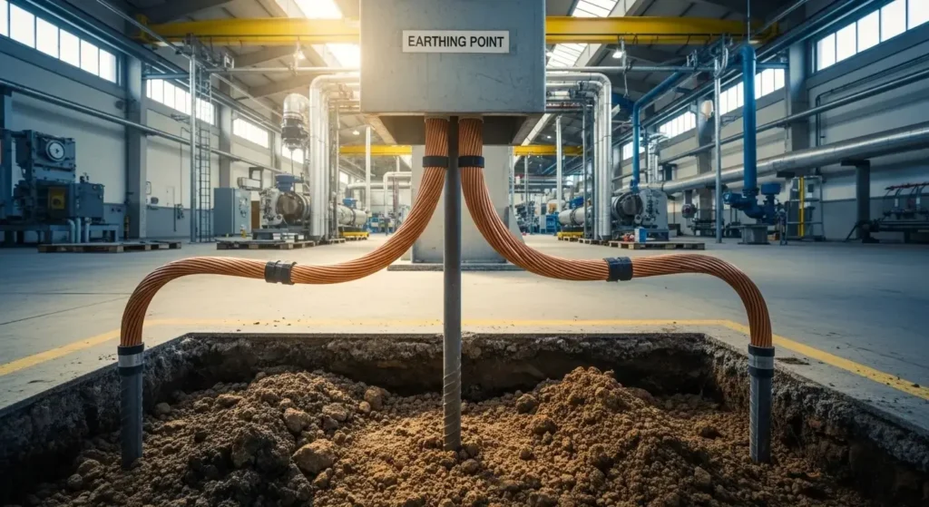
Imagine you are standing inside a large factory. Heavy motors are running, control panels are energized, and high-power machines operate day and night. Suddenly, a fault occurs inside one machine. If there is no proper earthing system, that metal body can become live and cause serious electric shock, fire, or equipment damage.
This is why Industrial Earthing is one of the most important safety systems in any industrial installation. It protects human life, prevents equipment failure, and ensures reliable system performance.
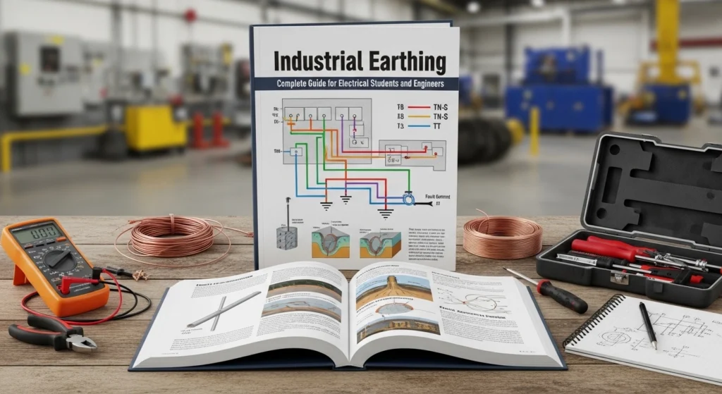
In this detailed guide, you will learn the Industrial Earthing working principle, different types of earthing systems, components used, advantages and disadvantages, applications, comparison with other grounding systems, selection guide, troubleshooting tips, and future trends.
As a senior electrical engineer, I can confidently say: if your earthing system is strong, your electrical system is safe. Let’s understand it step by step.
2. What is Industrial Earthing?
Industrial Earthing is the process of connecting non-current-carrying metal parts of electrical equipment to the earth (ground) to ensure safety during fault conditions.Industrial earthing is one of the most important safety practices used in electrical systems within factories, plants, and large industrial setups. It refers to the process of connecting electrical equipment and installations to the earth (ground) through a low-resistance path. The main purpose of industrial earthing is to protect human life, equipment, and systems from electrical faults such as leakage current, short circuits, and lightning surges. In an industrial environment where heavy machinery and high voltages are commonly used, even a small fault can lead to serious accidents, equipment damage, or fire hazards. That is why proper earthing is not optional but a mandatory requirement in all industrial electrical systems.
In simple terms, industrial earthing provides a safe path for unwanted electrical current to flow directly into the ground instead of passing through a person or sensitive equipment. For example, if a machine develops a fault and its metal body becomes live, the earthing system ensures that the current flows to the earth, causing protective devices like circuit breakers to trip immediately. This helps in preventing electric shocks and reducing the risk of accidents.
There are different types of industrial earthing methods such as plate earthing, pipe earthing, and grid earthing. Each method is selected based on soil condition, load requirement, and system design. A proper earthing system includes components like earth electrodes, conductors, clamps, and inspection chambers. The resistance of the earthing system should be kept as low as possible to ensure effective fault current flow.
Industrial earthing also plays a key role in stabilizing voltage levels and improving the performance of electrical systems. It helps in reducing electrical noise, protecting sensitive equipment, and ensuring smooth operation of machines. Regular maintenance and testing of the earthing system are essential to ensure its reliability over time.
In conclusion, industrial earthing is a critical safety and performance measure in any industrial electrical system. It not only protects lives but also enhances system efficiency and equipment lifespan.
In simple words, it provides a low-resistance path for fault current to safely flow into the ground.
Practical Example
Suppose insulation inside a motor fails and the phase wire touches the metal body. Without earthing, the motor body becomes live. If a worker touches it, electric shock can occur.
With proper Industrial Earthing:
- Fault current flows directly into the earth
- Protective devices (MCB/Relay) trip quickly
- The system becomes safe
This is why Industrial Earthing is essential in factories, power plants, substations, and large commercial buildings.
Industrial Earthing: Working Principle and System Overview
Industrial earthing is a safety system used in electrical installations to protect equipment, machinery, and human life from electric shock and electrical faults. The working principle of earthing is based on providing a low-resistance path for fault current to flow safely into the ground.
When a fault occurs in an electrical system—such as insulation failure, short circuit, or leakage current—the excess electric current does not remain in the equipment. Instead, it is immediately transferred to the earth through the earthing system. This is achieved using earthing conductors, electrodes, and grounding pits that connect electrical equipment directly to the ground.
The earth acts as a large natural conductor that can easily absorb fault current without causing damage. Because the resistance of the earthing path is very low, the current flows safely into the ground instead of passing through the human body or sensitive equipment. This helps in reducing the risk of electric shock, fire hazards, and equipment damage.
In industrial systems, earthing also ensures stable voltage levels and improves the overall reliability of electrical networks. It helps circuit protection devices like fuses and circuit breakers to operate quickly by allowing high fault current to flow, which triggers immediate disconnection of the faulty circuit.
Key Idea:
Industrial earthing works on the principle of safety through low-resistance grounding, ensuring that fault currents are safely discharged into the earth instead of causing harm.
The Industrial Earthing working principle is based on providing the lowest resistance path to ground for fault current.
Let’s understand step-by-step:
- Under normal conditions, current flows through phase and neutral.
- The equipment body remains non-energized.
- During a fault, phase touches metal body.
- Fault current flows through earthing conductor.
- Current reaches earth electrode.
- Protective device detects high current.
- Circuit breaker trips immediately.
Simple Analogy
Think of earthing like an emergency exit door in a building.
When everything is normal, nobody uses it. But in case of fire (fault), people use the emergency exit to escape safely.
Similarly, fault current uses the earthing path to safely escape into the ground.
4. Types / Classification of Industrial Earthing
There are different types of Industrial Earthing systems used depending on soil condition, load type, and safety requirements.
Plate Earthing System: Working Principle, Construction, and Applications
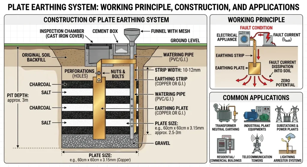
- A copper or GI plate is buried deep in the ground.
- Charcoal and salt are placed around it to reduce resistance.
- Used in large installations.
The plate earthing system is one of the most commonly used methods of electrical grounding in residential, commercial, and industrial installations. It is designed to safely discharge fault current into the earth, ensuring protection for both electrical equipment and human life. This system plays a vital role in maintaining electrical safety and system stability.
Working Principle of Plate Earthing
The working principle of plate earthing is based on providing a low-resistance path for electric current to flow directly into the ground. When a fault occurs in an electrical system, such as insulation failure or leakage current, the excess current is diverted through the earthing system. The buried metal plate acts as a conductor and transfers the fault current safely into the soil. Since the earth has very low potential and high absorption capacity, it neutralizes the current, preventing electric shock, fire hazards, and equipment damage. This process also helps protective devices like circuit breakers and fuses to operate quickly by allowing sufficient fault current to flow.
Construction of Plate Earthing System
In plate earthing, a metal plate made of copper or galvanized iron (GI) is buried vertically at a suitable depth in the ground, usually around 2.5 to 3 meters. The size of the plate is generally 600 mm × 600 mm or as per system requirements. The plate is surrounded by layers of charcoal and salt, which help improve soil conductivity and reduce earth resistance.
A copper or GI strip is securely connected to the plate and extended to the electrical system through a protective pipe. An inspection chamber with a cover is provided at the surface for maintenance and testing. Water is often added through a pipe to maintain soil moisture and ensure consistent grounding performance.
Applications of Plate Earthing
Plate earthing is widely used in:
- Residential buildings for household electrical safety
- Commercial complexes and offices
- Small to medium industrial plants
- Electrical panels and distribution systems
- Transformers and generators (light to medium load systems)
Plate earthing is a simple, cost-effective, and reliable grounding method that ensures safety, protects electrical equipment, and improves system performance. It is especially suitable for installations where moderate fault currents are expected and proper soil conditions are available.
Pipe Earthing System: Working Principle, Construction, and Applications
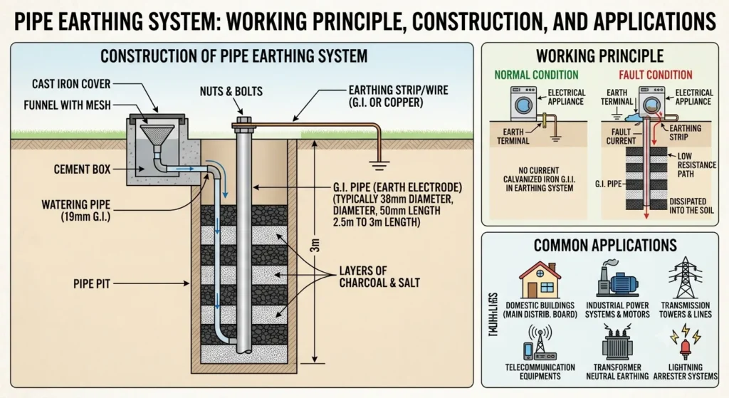
- Most common and economical method.
- A perforated GI pipe is buried vertically.
- Suitable for industries with moderate load.
The pipe earthing system is one of the most widely used and cost-effective methods of electrical grounding in modern electrical installations. It is commonly used in residential, commercial, and industrial systems to ensure safety, protect equipment, and provide a reliable path for fault current to flow into the ground.
Working Principle of Pipe Earthing
The working principle of pipe earthing is based on providing a low-resistance path for fault current to safely discharge into the earth. When an electrical fault occurs, such as leakage current, short circuit, or insulation failure, the excess current flows through the earthing system instead of passing through electrical equipment or humans. The galvanized iron (GI) pipe buried in the ground acts as a conductor that transfers this fault current directly into the soil. Since the earth has a very large surface area and low electrical potential, it absorbs the current safely, preventing electric shock, fire hazards, and equipment damage. This also allows protective devices like circuit breakers and fuses to operate quickly and isolate the faulty circuit.
Construction of Pipe Earthing System
In pipe earthing, a perforated galvanized iron (GI) pipe is used as the main earthing electrode. The pipe is buried vertically in the ground at a depth of around 2.5 to 3 meters or more, depending on soil conditions. The pipe is perforated with holes to allow moisture to penetrate, which improves conductivity and reduces earth resistance.
The surrounding area of the pipe is filled with layers of charcoal and salt to enhance soil conductivity and maintain low resistance. A GI or copper strip is connected to the pipe using a strong clamp and is extended to the electrical system for grounding purposes. A watering pipe is also installed to keep the soil moist, ensuring consistent and effective earthing performance. An inspection chamber is provided at the top for maintenance and testing.
Applications of Pipe Earthing
Pipe earthing is widely used in:
- Residential houses and apartments
- Commercial buildings and offices
- Industrial electrical installations
- Power distribution systems
- Electrical panels, transformers, and machinery
Pipe earthing is a highly efficient, economical, and reliable grounding method. It ensures electrical safety, protects human life, and improves the performance and stability of electrical systems by safely discharging fault currents into the earth.
Rod Earthing System: Working Principle, Construction, and Applications
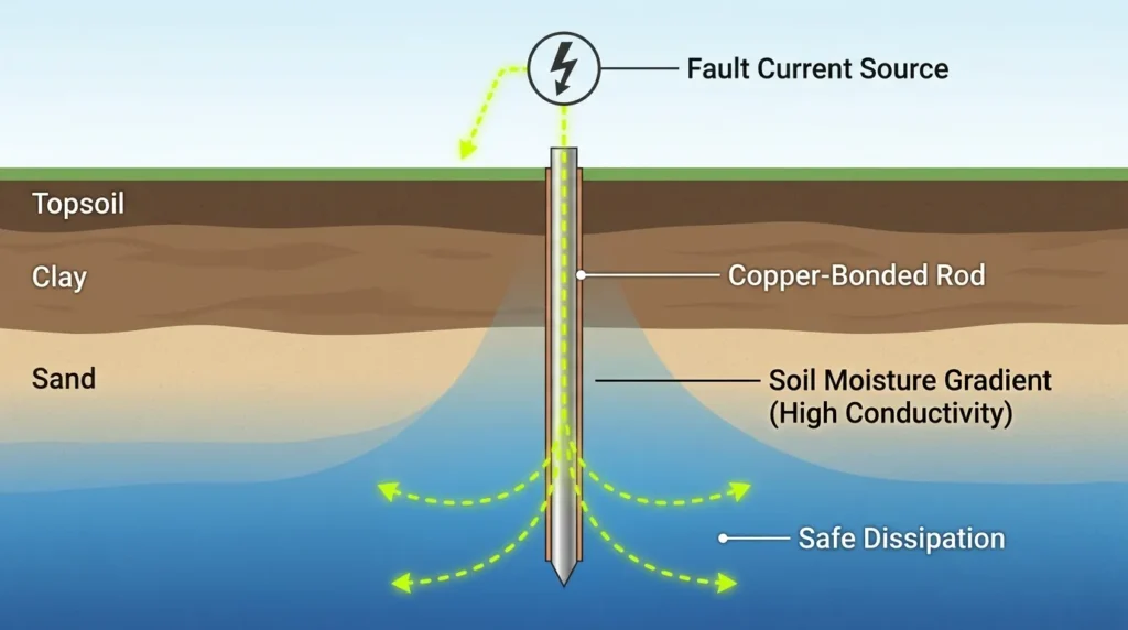
- Copper or steel rod driven deep into the soil.
- Quick installation.
- Used in rocky areas.
The rod earthing system is a simple, efficient, and widely used method of electrical grounding that ensures safety in residential, commercial, and industrial electrical installations. It provides a low-resistance path for fault current to flow safely into the earth, protecting both people and electrical equipment from electrical hazards.
Working Principle of Rod Earthing
The working principle of rod earthing is based on transferring fault current directly into the ground through a metal rod. When an electrical fault occurs, such as insulation failure or leakage current, the excess electricity flows through the earthing conductor into the grounding rod instead of passing through appliances or human bodies. The rod is deeply embedded in the soil, allowing the fault current to disperse safely over a large area. Since the earth has very low electrical potential, it absorbs the current effectively, preventing electric shocks, fire risks, and equipment damage. This also ensures that protective devices like circuit breakers and fuses quickly detect the fault and disconnect the supply.
Construction of Rod Earthing System
In rod earthing, a long copper or galvanized iron (GI) rod is used as the main grounding electrode. The rod is driven vertically into the ground to a considerable depth, depending on soil conditions and system requirements. Copper rods are preferred due to their high conductivity and corrosion resistance, while GI rods are more economical.
The rod is connected to the electrical system using a copper or GI strip or wire. To improve performance, the surrounding soil may be treated with conductive materials such as salt or bentonite clay to reduce earth resistance. In some installations, multiple rods are used in parallel to achieve better grounding efficiency. A test point or inspection chamber is also provided for maintenance and resistance measurement.
Applications of Rod Earthing
Rod earthing is commonly used in:
- Residential buildings and housing systems
- Small commercial electrical installations
- Lightning protection systems
- Telecom towers and communication systems
- Electrical panels and distribution boards
- Areas with limited space for earthing pits
Rod earthing is a reliable, economical, and space-saving grounding method. It provides effective protection against electrical faults, enhances system stability, and ensures the safety of both users and electrical equipment in a wide range of applications.
Strip or Wire Earthing System: Working Principle, Construction, and Applications
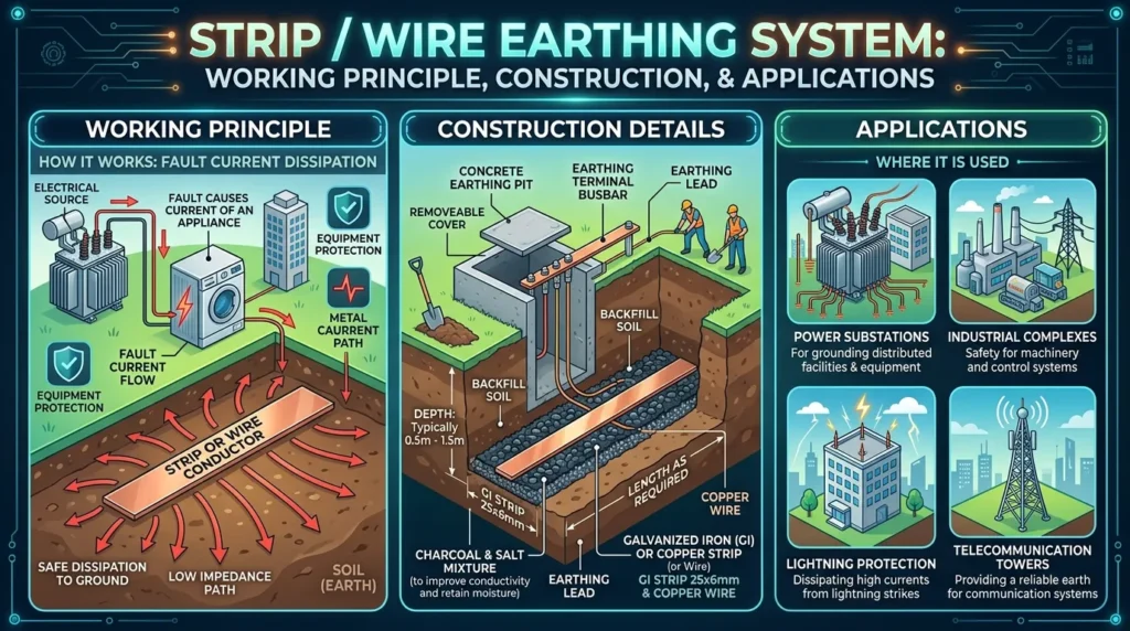
- Metal strip buried horizontally.
- Used in substations and transmission lines.
The strip or wire earthing system is an important and widely used method of electrical grounding that ensures safety, system stability, and protection of electrical equipment. It is commonly used in industrial installations, power distribution systems, and areas where a long grounding path is required. This method uses metal strips or wires to create a low-resistance path for fault current to safely flow into the earth.
Working Principle of Strip or Wire Earthing
The working principle of strip or wire earthing is based on providing a continuous and low-resistance path between electrical equipment and the ground. When a fault occurs in an electrical system, such as insulation failure or leakage current, the excess electricity flows through the earthing conductor instead of passing through the equipment or human body. The metal strip or wire, usually made of copper or galvanized iron (GI), carries this fault current safely into the ground. Since the earth has a very large surface area and low electrical potential, it absorbs the current effectively, reducing the risk of electric shock, fire hazards, and equipment damage. This also helps protective devices like circuit breakers and fuses operate quickly by detecting and isolating the fault.
Construction of Strip or Wire Earthing System
In strip or wire earthing, a copper or GI strip/wire is buried horizontally in the ground at a specified depth, or sometimes laid in trenches in a grid or loop pattern. The size and length of the strip depend on the load requirements and soil conditions. Copper strips are preferred due to their high conductivity and corrosion resistance, while GI strips are more economical.
To improve conductivity, the trench is filled with layers of salt, charcoal, or bentonite compound, which helps reduce earth resistance. The strip is connected to electrical equipment through a strong conductor, ensuring a reliable grounding path. In large installations, multiple strips may be used in parallel to achieve better grounding efficiency and safety.
Applications of Strip or Wire Earthing
Strip or wire earthing is commonly used in:
- Industrial plants and factories
- Power generation and distribution systems
- Substations and electrical grids
- Large buildings and commercial complexes
- Telecommunication and signal grounding systems
- Sensitive electronic equipment installations
Strip or wire earthing is a highly effective grounding method that provides a strong and stable path for fault current. It enhances electrical safety, protects equipment, and ensures smooth operation of electrical systems, especially in large-scale and high-load environments.
Mat Earthing (Grid Earthing) for Industrial Electrical Safety
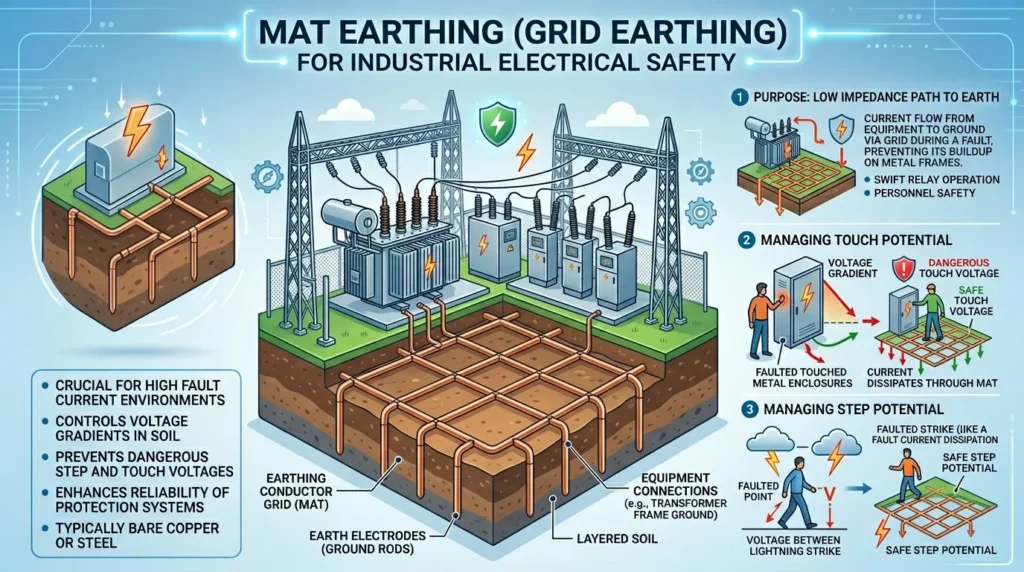
- Network of conductors buried underground.
- Used in power plants and substations.
- Provides uniform ground potential.
Mat earthing, also known as grid earthing, is a highly effective and widely used grounding system in large industrial and power installations. It is designed to provide maximum electrical safety by distributing fault currents evenly into the ground, reducing the risk of electric shock, equipment damage, and fire hazards. This system is especially suitable for substations, power plants, and heavy industrial environments where large fault currents are expected.
Working Principle of Mat Earthing
The working principle of mat earthing is based on creating a low-resistance network of interconnected conductors buried beneath the ground. When an electrical fault occurs, such as insulation failure or short circuit, the fault current is safely distributed through this grid network into the earth. Instead of concentrating at a single point, the current spreads over a wide area, reducing voltage rise at any one location. This minimizes the risk of dangerous step voltage and touch voltage, ensuring safety for both workers and equipment. The earth acts as a natural sink that absorbs the fault current efficiently due to its large conductive mass.
Construction of Mat Earthing System
In mat earthing, a network of copper or galvanized iron (GI) strips or conductors is laid horizontally in a grid pattern beneath the ground surface. These conductors are interconnected at regular intervals to form a mesh-like structure. The depth of installation is carefully designed, usually below the surface level, to ensure safety and durability.
Vertical earthing rods are often added at grid intersections to further reduce resistance and improve fault current dissipation. The entire grid is buried in soil that may be treated with materials like salt, charcoal, or bentonite to enhance conductivity. All electrical equipment in the facility is connected to this earthing grid to ensure a common grounding potential.
Applications of Mat Earthing
Mat earthing is commonly used in:
- Electrical substations
- Power generation plants
- Large industrial complexes
- Transformer stations
- High-voltage switchyards
- Heavy machinery and manufacturing plants
Mat earthing (grid earthing) is one of the safest and most reliable grounding systems for industrial applications. It ensures uniform fault current distribution, minimizes voltage hazards, and provides excellent protection for both personnel and electrical equipment, making it essential for high-power electrical environments.
Chemical Earthing System: Working Principle, Construction, and Applications
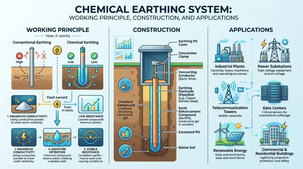
- Uses special chemical compounds.
- Maintains low resistance for long time.
- Ideal for dry and sandy soil.
Each type has different Industrial Earthing advantages and disadvantages depending on soil and system size
Chemical earthing is an advanced and highly efficient grounding method used in modern electrical systems to ensure safety, stability, and reliable performance. It is widely used in residential, commercial, and industrial installations where low earth resistance and long-term performance are required. Unlike traditional earthing methods, chemical earthing uses special conductive compounds to improve soil conductivity and maintain consistent grounding efficiency.
Working Principle of Chemical Earthing
The working principle of chemical earthing is based on reducing earth resistance by using conductive chemicals around the earthing electrode. When a fault occurs in an electrical system, the fault current flows through the earthing electrode into the surrounding conductive compound and then safely disperses into the soil. The chemical mixture maintains moisture and conductivity, ensuring a stable low-resistance path for current flow. This helps protect electrical equipment, prevent electric shock, and reduce fire hazards. It also ensures that protective devices like circuit breakers and fuses operate quickly by allowing fault current to pass efficiently.
Construction of Chemical Earthing System
In chemical earthing, a copper or galvanized iron (GI) electrode is installed vertically in the ground at a suitable depth. Around the electrode, a specially prepared conductive compound—such as bentonite, graphite, or other earthing chemicals—is filled. This compound plays a key role in maintaining moisture and improving soil conductivity.
A GI or copper strip is connected to the electrode and linked to the electrical system for grounding. The earthing pit is designed to retain moisture, and sometimes a watering pipe is installed to maintain proper humidity levels inside the pit. This ensures consistent performance even in dry or rocky soil conditions. The system requires minimal maintenance and provides long-lasting stability compared to traditional earthing methods.
Applications of Chemical Earthing
Chemical earthing is commonly used in:
- Residential buildings and apartments
- Commercial complexes and shopping centers
- Industrial plants and factories
- Telecom towers and data centers
- Electrical substations and distribution systems
- Sensitive electronic and IT equipment installations
Chemical earthing is a modern, reliable, and low-maintenance grounding solution that ensures excellent electrical safety. By maintaining low and stable earth resistance, it enhances system performance, protects equipment, and provides long-term protection in a wide range of electrical applications.
5. Main Components of Industrial Earthing System (Detailed Explanation)
An industrial earthing system is made up of several essential components that work together to ensure electrical safety, protect equipment, and provide a low-resistance path for fault current to flow safely into the ground. Each component has a specific role, and proper installation of all parts is necessary for efficient and long-lasting performance.
Earth Electrode
The earth electrode is the most important part of the earthing system. It is a metal conductor, usually made of copper, galvanized iron (GI), or steel, that is buried deep in the soil. Its main function is to make direct contact with the ground and safely discharge fault current into the earth. The effectiveness of the entire earthing system depends largely on the quality, material, and depth of the electrode. A good earth electrode ensures low resistance and efficient current dissipation.
Earthing Conductor
The earthing conductor is the wire or strip that connects the electrical equipment to the earth electrode. It provides a safe and direct path for fault current to flow into the ground. This conductor is usually made of copper or GI material due to its high conductivity and durability. It plays a key role in preventing electric shock by ensuring that any leakage current is safely diverted away from equipment and users.
Earth Pit
The earth pit is the physical location where the earth electrode is installed. It is carefully designed and prepared to maintain proper moisture and soil conditions. The pit is often filled with conductive materials such as salt, charcoal, or bentonite to improve soil conductivity and reduce earth resistance. A well-maintained earth pit ensures stable and efficient earthing performance.
Earth Busbar
The earth busbar is a metallic strip or bar installed inside electrical control panels. It acts as a common connection point where all earthing conductors from different equipment are connected. This ensures uniform grounding and simplifies the distribution of fault current to the earth system. It also helps in easy maintenance and system organization.
Inspection Chamber
The inspection chamber is a small accessible enclosure provided at the top of the earth pit. It allows technicians to check, test, and maintain the earthing system. Through this chamber, earth resistance can be measured, and water or maintenance materials can be added when needed. Regular inspection ensures the earthing system remains effective and safe over time.
All components of an industrial earthing system work together to ensure electrical safety, system stability, and equipment protection. Proper design, installation, and maintenance of each part are essential for achieving low resistance, high efficiency, and long-term reliability in industrial electrical systems.
6. Advantages of Industrial Earthing
Industrial Earthing advantages and disadvantages must be clearly understood. Let’s start with benefits:
- Protects human life from electric shock
- Prevents fire hazards
- Protects expensive equipment
- Improves system stability
- Ensures proper operation of relays
- Reduces electrical noise
- Complies with safety standards
In simple words, good earthing saves money and lives.
7. Disadvantages / Limitations
Even though it is essential, Industrial Earthing has some limitations:
- Installation cost can be high
- Requires regular maintenance
- Soil condition affects performance
- Corrosion can damage electrodes
- Poor design may increase resistance
If not maintained properly, the system may fail during fault.
8. Industrial Earthing Applications
Industrial Earthing applications are very wide.
Home Applications
- Large residential buildings
- Generator systems
- Solar systems
Industrial Applications
- Factories
- Manufacturing plants
- Power plants
- Substations
- Heavy machinery
Modern Technology Uses
- Data centers
- Telecom towers
- Renewable energy systems
- EV charging stations
Wherever electricity is used in large quantity, Industrial Earthing is mandatory.
9. Comparison Section
Difference Between Industrial Earthing and Residential Earthing
| Feature | Industrial Earthing | Residential Earthing |
|---|---|---|
| Load Capacity | Very High | Low to Medium |
| System Complexity | Complex | Simple |
| Safety Requirement | Critical | Moderate |
| Cost | Higher | Lower |
| Maintenance | Regular testing required | Occasional testing |
The main difference between residential earthing and industrial earthing is load capacity and safety level.
Industrial systems require stronger grounding due to high fault currents.
10. Selection Guide
Choosing the right Industrial Earthing system depends on:
- Soil resistivity
- Type of load
- Fault current level
- Safety standards
- Budget
Tips for Beginners
- Always measure soil resistance first
- Use copper electrode for better conductivity
- Keep earth resistance below recommended value
- Follow local electrical codes
- Perform periodic testing
A well-designed earthing system should have low resistance and high reliability.
11. Common Problems and Solutions in Industrial Earthing Systems (FAQ Guide with Detailed Explanation)
Industrial earthing systems are designed to ensure electrical safety, but over time they may develop problems due to environmental conditions, poor maintenance, or installation faults. Understanding these common issues and their solutions is important for maintaining a safe, efficient, and reliable grounding system.
Q1: Why is earth resistance high?
High earth resistance is one of the most common problems in earthing systems. It usually occurs when the soil around the electrode becomes dry, rocky, or loses its natural moisture content. Poor installation depth or insufficient conductive material can also increase resistance.
Solution:
To reduce earth resistance, the soil should be kept moist by adding water regularly. Using chemical earthing compounds such as bentonite or conductive gel helps improve soil conductivity. In some cases, increasing the size or number of electrodes can also reduce resistance and improve system performance.
Q2: Why is the circuit breaker not tripping during a fault?
If a circuit breaker does not trip during a fault, it may indicate poor or broken earthing connection. High resistance in the earthing system prevents sufficient fault current from flowing, which stops the protective device from activating properly.
Solution:
Check the continuity of the earthing conductor and measure earth resistance using proper testing equipment. Repair any loose or damaged connections and ensure the earthing system provides a low-resistance path for fault current. Proper maintenance ensures that breakers operate correctly during electrical faults.
Q3: Why is the electrode corroded?
Electrode corrosion occurs due to chemical reactions between metal and soil moisture over time. Poor-quality materials or highly acidic/alkaline soil conditions can speed up corrosion, reducing the efficiency and lifespan of the earthing system.
Solution:
Use corrosion-resistant materials such as copper-bonded steel or galvanized iron electrodes. Chemical earthing systems with protective compounds also help reduce corrosion and extend electrode life. Regular inspection and replacement of damaged electrodes are necessary for long-term reliability.
Q4: How often should earthing system testing be done?
Regular testing is essential to ensure that the earthing system remains safe and effective. Over time, soil conditions and system components may change, affecting performance.
Answer:
In industrial systems, earthing should be tested at least once every year, while critical installations may require more frequent testing. Regular maintenance ensures consistent low resistance, proper fault protection, and overall system safety.
Proper maintenance and timely troubleshooting of industrial earthing systems are essential for ensuring electrical safety and system reliability. Regular inspection, testing, and corrective actions help prevent failures and protect both equipment and human life.
12. Future Trends in Industrial Earthing
The future of Industrial Earthing is becoming more advanced.
- Smart grounding monitoring systems
- Online earth resistance sensors
- Improved corrosion-resistant materials
- Integration with IoT systems
- Advanced simulation software for design
Industries are moving towards automated safety systems.
With renewable energy and EV systems increasing, grounding technology will continue to improve.
13. Conclusion
Industrial Earthing is not just a safety requirement; it is the backbone of any industrial electrical system. It protects people, equipment, and infrastructure from dangerous fault currents.
We discussed the Industrial Earthing working principle, types, components, applications, advantages and disadvantages, comparison with residential systems, and troubleshooting methods.
As an engineer, always remember: never compromise on grounding design. A properly installed and maintained earthing system ensures long-term safety and performance.
Keep learning, keep testing, and always follow electrical standards. Safety in electricity begins with proper earthing.