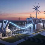
Electricity being generated at a power plant at 11kV. If we send that same voltage directly to homes, it will not be efficient for long-distance transmission. On the other hand, if we send extremely high voltage directly into houses, it would be dangerous. So how do we safely increase and decrease voltage levels? The answer is a transformer.
The transformer working principle is one of the most important concepts in electrical engineering. Whether you are a student, technician, or engineer, understanding how a transformer works helps you design safe power systems, troubleshoot faults, and select proper equipment.
In this article, you will learn what a transformer is, the transformer working principle in simple steps, types of transformers, components, transformer applications, transformer advantages and disadvantages, and practical troubleshooting tips. By the end, you will clearly understand how transformers transfer electrical energy efficiently without direct electrical connection.
2. What is Transformer Working Principle?
Clear Definition
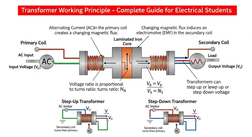
The transformer working principle is based on electromagnetic induction, where electrical energy is transferred from one coil to another through a magnetic field without direct electrical connection.
Simple Explanation
A transformer changes voltage level:
- Increase voltage → Step-up transformer
- Decrease voltage → Step-down transformer
It works only on AC (Alternating Current).
Practical Example
At a power station:
- Voltage is increased to reduce transmission losses.
- Near your home, voltage is reduced to 220V or 230V.
- Your appliances operate safely.
All this happens because of the transformer working principle.
3. Transformer Working Principle (Step-by-Step)
The transformer working principle is based on Faraday’s Law of Electromagnetic Induction.
Let’s understand step by step.
AC Supply to Primary Coil
When an AC supply is connected to the primary coil of a transformer, alternating current begins to flow through the winding. This alternating current continuously changes its direction and magnitude according to the AC frequency, usually 50 Hz or 60 Hz. As the current flows through the primary coil, it produces a changing magnetic field around the coil. The transformer core, which is made of laminated soft iron, carries this magnetic field efficiently from the primary winding to the secondary winding.
The magnetic field generated by the primary coil is not constant because AC current is always changing. Due to this changing magnetic flux, a voltage is induced in the secondary coil according to Faraday’s Law of Electromagnetic Induction. This process is called mutual induction. The transformer transfers electrical energy from one circuit to another without direct electrical connection between the coils.
The amount of voltage induced in the secondary coil depends mainly on the number of turns in both windings. If the secondary winding has more turns than the primary winding, the transformer acts as a step-up transformer and increases voltage. If the secondary winding has fewer turns, it becomes a step-down transformer and reduces voltage.
An AC supply is essential for transformer operation because transformers work only with changing magnetic fields. A DC supply cannot continuously produce changing flux, so it cannot operate a transformer properly and may even damage the winding due to overheating.
This principle is widely used in power transmission systems, mobile chargers, adapters, electrical substations, and industrial machines. The process of supplying AC to the primary coil is therefore the basic working principle of every transformer used in modern electrical and electronic systems.
- Alternating current flows through the primary winding.
- A changing magnetic field is created around it.
Magnetic Flux in Core
Magnetic flux in the core is one of the most important concepts in transformers, motors, generators, and other electromagnetic devices. When electric current flows through a coil or winding, it creates a magnetic field around the conductor. In devices such as transformers, this magnetic field passes through an iron or steel core, producing what is called magnetic flux. Magnetic flux represents the total number of magnetic field lines flowing through a specific area of the core.
In a transformer, when alternating current (AC) flows through the primary winding, it produces a continuously changing magnetic field. The laminated iron core provides a low-resistance path for this magnetic field, allowing magnetic flux to move efficiently through the core material. The changing magnetic flux then links with the secondary winding and induces voltage according to Faraday’s Law of Electromagnetic Induction.
Magnetic flux is usually represented by the symbol Φ (phi) and measured in Webers (Wb). The amount of magnetic flux depends on several factors, including:
- Number of turns in the coil
- Strength of current flowing through the winding
- Type and size of core material
- Frequency of AC supply
A high-quality core material such as soft iron or silicon steel is used because it improves magnetic flow and reduces energy losses. Laminated cores are commonly used to minimize eddy current losses and overheating.
If magnetic flux becomes too high, the core may become saturated. Core saturation reduces transformer efficiency and causes excessive heating. Therefore, transformers are carefully designed to maintain proper magnetic flux levels.
Magnetic flux in the core is essential for energy transfer in electrical machines. Without magnetic flux, transformers would not be able to transfer electrical energy from one winding to another. This principle is widely used in power systems, electrical appliances, industrial equipment, and electronic devices used in daily life.
- The magnetic field passes through the iron core.
- The core guides magnetic flux efficiently.
Induced Voltage in Secondary Coil
When alternating current (AC) flows through the primary winding of a transformer, it creates a changing magnetic field around the coil. This changing magnetic field passes through the transformer core and links with the secondary winding. According to Faraday’s Law of Electromagnetic Induction, a changing magnetic flux always induces an electromotive force (EMF) or voltage in a nearby conductor. This produced voltage in the secondary winding is called the induced voltage in the secondary coil.
The induced voltage is generated without any direct electrical connection between the primary and secondary coils. The transfer of energy takes place through the magnetic field inside the transformer core. This process is known as mutual induction and is the basic working principle of a transformer.
The amount of induced voltage in the secondary coil depends mainly on:
- Number of turns in the secondary winding
- Number of turns in the primary winding
- Strength of magnetic flux
- Frequency of AC supply
The relationship between primary and secondary voltage is given by the transformer turns ratio formula:
[
\frac{V_s}{V_p} = \frac{N_s}{N_p}
]
Where:
- (V_s) = Secondary voltage
- (V_p) = Primary voltage
- (N_s) = Number of turns in secondary coil
- (N_p) = Number of turns in primary coil
If the secondary winding has more turns than the primary winding, the transformer increases voltage and acts as a step-up transformer. If it has fewer turns, it reduces voltage and acts as a step-down transformer.
Induced voltage in the secondary coil is used in many electrical and electronic systems such as power transmission, adapters, mobile chargers, televisions, industrial machines, and substations. Efficient induction of voltage allows safe and reliable transfer of electrical energy between circuits. This principle makes transformers one of the most important devices in modern electrical engineering.
- The changing magnetic field cuts the secondary winding.
- According to electromagnetic induction, voltage is induced.
Important Points
- No direct wire connection between primary and secondary.
- Energy transfer happens through magnetic flux.
- Frequency remains the same.
- Only voltage and current change.
Easy Analogy
Think of two people holding a rope:
- One person shakes the rope.
- The other person feels movement without direct touch.
Similarly, magnetic flux transfers energy between coils.
4. Types / Classification of Transformers
Transformers are classified based on function and construction.
Step-Up Transformer
A step-up transformer is an electrical device used to increase the voltage level of alternating current (AC) from a lower value to a higher value. It works on the principle of electromagnetic induction and is widely used in power generation, transmission systems, and electronic equipment. In a step-up transformer, the voltage at the secondary winding is greater than the voltage at the primary winding.
The transformer consists mainly of two windings called the primary winding and the secondary winding, wound around a laminated iron core. When AC supply is connected to the primary coil, alternating current flows through it and creates a changing magnetic field. This changing magnetic flux passes through the iron core and links with the secondary winding. According to Faraday’s Law, this varying magnetic field induces voltage in the secondary coil.
In a step-up transformer, the number of turns in the secondary winding is greater than the number of turns in the primary winding. Due to this higher number of turns, the induced voltage in the secondary side becomes higher than the input voltage. The transformer voltage ratio is expressed as:
[
\frac{V_s}{V_p} = \frac{N_s}{N_p}
]
Where:
- (V_s) = Secondary voltage
- (V_p) = Primary voltage
- (N_s) = Number of turns in secondary winding
- (N_p) = Number of turns in primary winding
For example, if the primary winding has 100 turns and the secondary winding has 500 turns, the output voltage becomes five times greater than the input voltage.
Step-up transformers are extremely important in electrical power systems. In power stations, generated voltage is stepped up to very high levels before transmission. High-voltage transmission reduces current flow and minimizes power losses in transmission lines. After reaching cities and homes, other transformers reduce the voltage again for safe use.
Advantages of Step-Up Transformers
- Increases voltage efficiently
- Reduces transmission losses
- Improves power transmission over long distances
- Works with high efficiency
Disadvantages
- Operates only on AC supply
- Requires insulation for high voltage safety
- Large transformers are expensive
Applications of Step-Up Transformers
- Electrical power transmission systems
- Power generation stations
- X-ray machines
- Inverters and UPS systems
- Industrial electrical equipment
In conclusion, a step-up transformer is a vital electrical device that increases AC voltage for efficient power transmission and industrial applications. It plays an essential role in modern electrical and electronic systems worldwide.
- Increases voltage.
- Decreases current.
- Used in power transmission.
Example: Power plant transformer.
Step-Down Transformer
A step-down transformer is an electrical device used to decrease the voltage level of alternating current (AC) from a higher value to a lower value. It works on the principle of electromagnetic induction and is widely used in homes, industries, electronic devices, and power distribution systems. In a step-down transformer, the voltage at the secondary winding is lower than the voltage at the primary winding.
A transformer mainly consists of two windings called the primary winding and the secondary winding, wound around a laminated soft iron core. When AC supply is connected to the primary winding, alternating current flows through the coil and produces a changing magnetic field. This magnetic field passes through the iron core and links with the secondary winding. According to Faraday’s Law of Electromagnetic Induction, this changing magnetic flux induces voltage in the secondary coil.
In a step-down transformer, the number of turns in the secondary winding is less than the number of turns in the primary winding. Because of fewer turns in the secondary coil, the output voltage becomes lower than the input voltage. The transformer turns ratio formula is:
[
\frac{V_s}{V_p} = \frac{N_s}{N_p}
]
Where:
- (V_s) = Secondary voltage
- (V_p) = Primary voltage
- (N_s) = Number of turns in secondary winding
- (N_p) = Number of turns in primary winding
For example, if the primary winding has 1000 turns and the secondary winding has 100 turns, the output voltage becomes one-tenth of the input voltage.
Step-down transformers are very important in power distribution systems. Electricity generated at power stations is transmitted at high voltage to reduce losses. Before reaching homes and offices, step-down transformers reduce the voltage to safe levels suitable for domestic and commercial use. They are also used in adapters, chargers, televisions, UPS systems, and electronic circuits.
Advantages of Step-Down Transformers
- Provides safe low voltage supply
- Reduces voltage efficiently
- High operating efficiency
- Essential for household electronics
- Reliable and durable operation
Disadvantages
- Works only with AC supply
- Large transformers occupy more space
- High current on secondary side may cause heating
Applications of Step-Down Transformers
- Power distribution systems
- Mobile chargers and adapters
- Electronic devices and appliances
- Industrial control circuits
- Welding machines and UPS systems
In conclusion, a step-down transformer is a very important electrical device used to safely reduce AC voltage for practical applications. It plays a major role in electrical distribution and modern electronic systems, making electricity suitable for homes, offices, and industries.
- Decreases voltage.
- Increases current.
- Used in distribution systems.
Example: Pole-mounted transformer near houses.
Isolation Transformer
An isolation transformer is a special type of transformer used to electrically separate one circuit from another while still transferring electrical power through electromagnetic induction. Unlike ordinary transformers, the main purpose of an isolation transformer is not to increase or decrease voltage significantly, but to provide electrical isolation between the input and output circuits. In most cases, the primary and secondary windings have an equal number of turns, so the output voltage remains nearly the same as the input voltage.
An isolation transformer works on the principle of mutual induction. When alternating current (AC) flows through the primary winding, it creates a changing magnetic field around the transformer core. This changing magnetic flux passes through the laminated iron core and induces voltage in the secondary winding. Since there is no direct electrical connection between the two windings, electrical energy is transferred safely through the magnetic field.
The primary and secondary windings are completely separated from each other. This separation protects electrical equipment and users from electric shock, voltage spikes, and electrical noise. Isolation transformers are widely used in sensitive electronic systems, medical equipment, laboratories, communication systems, and industrial applications where safety and clean power supply are very important.
Construction of Isolation Transformer
An isolation transformer mainly consists of:
- Primary winding
- Secondary winding
- Laminated iron core
- Insulation materials
- Protective casing
Both windings are insulated carefully to prevent direct current flow between circuits.
Working Principle
The working process is simple:
- AC supply is connected to the primary winding.
- Alternating current produces magnetic flux in the core.
- Magnetic flux links with the secondary winding.
- Voltage is induced in the secondary coil.
- Power is transferred without direct electrical contact.
Because of this isolation, faults or shocks from one side are less likely to pass to the other side.
Advantages of Isolation Transformer
- Provides electrical safety
- Protects against electric shock
- Reduces electrical noise and interference
- Protects sensitive electronic devices
- Improves equipment reliability
- Prevents ground loop problems
Disadvantages
- Larger size and weight
- More expensive than ordinary transformers
- Generates heat during operation
- Requires regular maintenance in industrial use
Applications of Isolation Transformer
Isolation transformers are used in many important areas, including:
- Medical equipment and hospitals
- Computer systems and servers
- Audio and communication systems
- Industrial control panels
- Laboratory instruments
- UPS and power backup systems
- Sensitive testing equipment
In hospitals, isolation transformers are especially important because they protect patients and medical staff from electrical leakage currents.
Difference Between Isolation Transformer and Step-Down Transformer
| Feature | Isolation Transformer | Step-Down Transformer |
|---|---|---|
| Main Purpose | Electrical isolation | Reduce voltage |
| Turns Ratio | Usually 1:1 | Secondary turns fewer |
| Safety | Very high | Moderate |
| Voltage Change | Little or none | Significant reduction |
An isolation transformer is an essential electrical device designed mainly for safety, protection, and noise reduction. By separating two circuits electrically, it protects people and equipment from electrical faults and interference. Its ability to provide safe and clean power makes it highly important in medical, industrial, and electronic applications. Isolation transformers continue to play a major role in modern electrical systems where reliability and safety are critical.
- Same input and output voltage.
- Provides electrical isolation.
- Improves safety.
Power Transformer
A power transformer is a large electrical device used to transfer electrical energy from one circuit to another through electromagnetic induction. Its main purpose is to increase or decrease voltage levels in electrical power systems. Power transformers are mainly used in power generation stations, transmission networks, and substations for efficient transfer of electrical energy over long distances.
Power transformers work only with alternating current (AC) supply and operate on the principle of Faraday’s Law of Electromagnetic Induction. When AC flows through the primary winding, it creates a changing magnetic field around the transformer core. This changing magnetic flux passes through the laminated iron core and induces voltage in the secondary winding. Depending on the turns ratio, the transformer either increases voltage (step-up transformer) or decreases voltage (step-down transformer).
A power transformer consists of several important parts:
- Primary winding
- Secondary winding
- Laminated magnetic core
- Transformer oil
- Cooling system
- Conservator tank
- Bushings and protective devices
The transformer core is usually made of laminated silicon steel to reduce energy losses caused by eddy currents. Transformer oil is used for insulation and cooling purposes.
Power transformers are generally designed for high-voltage applications and operate with maximum efficiency near full load conditions. In power stations, generated electricity is stepped up to very high voltages using power transformers before transmission. High-voltage transmission reduces current flow and minimizes power losses in transmission lines. At receiving substations, voltage is reduced again for safe distribution to homes and industries.
Working Principle of Power Transformer
The working process includes:
- AC supply enters the primary winding.
- Magnetic flux is produced in the core.
- Flux links both windings.
- Voltage is induced in the secondary winding.
- Electrical power is transferred without direct electrical connection.
The voltage relationship depends on the turns ratio:
[
\frac{V_s}{V_p} = \frac{N_s}{N_p}
]
Where:
- (V_s) = Secondary voltage
- (V_p) = Primary voltage
- (N_s) = Secondary turns
- (N_p) = Primary turns
Advantages of Power Transformer
- High efficiency in power transmission
- Reduces transmission losses
- Reliable and long-lasting operation
- Supports high-voltage systems
- Requires less maintenance
Disadvantages
- Large size and heavy weight
- Expensive installation cost
- Operates only with AC supply
- Cooling system required for high loads
Applications of Power Transformer
Power transformers are widely used in:
- Power generation stations
- Electrical substations
- Transmission networks
- Heavy industries
- Renewable energy systems
- Large commercial buildings
They are essential for modern electrical grids and long-distance electricity transmission.
Difference Between Power Transformer and Distribution Transformer
| Feature | Power Transformer | Distribution Transformer |
|---|---|---|
| Usage | Transmission systems | Distribution systems |
| Voltage Level | Very high | Lower voltage |
| Efficiency | Best at full load | Best at partial load |
| Size | Larger | Smaller |
A power transformer is one of the most important devices in electrical power systems. It allows efficient transmission and distribution of electricity by increasing or decreasing voltage levels according to system requirements. With high efficiency, reliable performance, and strong construction, power transformers play a vital role in supplying electrical energy to industries, businesses, and homes around the world.
- Used in power generation stations.
- High voltage handling capacity.
- Operates at full load.
Distribution Transformer
Distribution Transformer
A distribution transformer is an electrical device used to step down high voltage electricity to a lower, safe level for use in homes, shops, offices, and small industries. It is the final stage of the power distribution system, which ensures that electrical energy is delivered safely and efficiently to consumers.
Distribution transformers work on the principle of electromagnetic induction. When alternating current (AC) flows through the primary winding, it produces a changing magnetic field in the transformer core. This magnetic flux induces voltage in the secondary winding. Since the secondary winding has fewer turns than the primary winding, the output voltage is reduced to a usable level.
These transformers are designed to operate efficiently at low load conditions because electricity demand changes throughout the day. Unlike power transformers, which work at full load in transmission systems, distribution transformers handle varying loads in residential and commercial areas.
A distribution transformer typically includes:
- Primary winding
- Secondary winding
- Laminated iron core
- Oil tank (in oil-cooled types)
- Cooling fins or radiators
- Protective devices like fuses and surge protectors
The core is made of silicon steel laminations to reduce energy losses such as eddy current loss and hysteresis loss. This improves efficiency and ensures long-term performance.
Working Principle of Distribution Transformer
The working process is simple:
- High-voltage AC supply enters the primary winding.
- Current produces a changing magnetic field in the core.
- Magnetic flux links to the secondary winding.
- Lower voltage is induced in the secondary coil.
- Safe electricity is supplied to consumers.
The voltage transformation follows the formula:
[
\frac{V_s}{V_p} = \frac{N_s}{N_p}
]
Where:
- (V_s) = Secondary voltage
- (V_p) = Primary voltage
- (N_s) = Secondary turns
- (N_p) = Primary turns
Advantages of Distribution Transformer
- Provides safe voltage for domestic use
- High efficiency at low load
- Reliable and long-lasting
- Requires minimal maintenance
- Essential for local power supply
Disadvantages
- Energy losses still occur (core and copper losses)
- Requires regular inspection
- Cannot operate without AC supply
- Large units may need oil cooling
Applications of Distribution Transformer
Distribution transformers are widely used in:
- Residential electricity supply
- Commercial buildings
- Street lighting systems
- Small industries and workshops
- Rural electrification systems
They play a key role in delivering electricity from substations to end users safely and efficiently.
Difference Between Power Transformer and Distribution Transformer
| Feature | Power Transformer | Distribution Transformer |
|---|---|---|
| Location | Transmission system | Near consumers |
| Load | Full load operation | Variable load |
| Voltage Level | Very high | Low voltage output |
| Efficiency Focus | Maximum at full load | Maximum at low load |
A distribution transformer is a crucial part of the electrical power system that ensures safe and efficient delivery of electricity to consumers. By reducing high transmission voltage to usable levels, it makes electrical energy suitable for everyday use in homes and businesses. Its reliability, efficiency, and essential role in power distribution make it one of the most important components of modern electrical infrastructure.
- Used near consumer areas.
- Operates at varying load.
- Supplies homes and small industries.
5. Main Components of Transformer
Understanding components helps you understand the transformer working principle better.
1. Core
- Made of laminated silicon steel.
- Provides magnetic path.
- Reduces energy losses.
2. Primary Winding
- Connected to input supply.
- Creates magnetic field.
3. Secondary Winding
- Delivers output voltage.
- Receives induced voltage.
4. Insulation
- Prevents short circuit.
- Ensures safety.
5. Transformer Oil (In large transformers)
- Cooling purpose.
- Insulation support.
6. Tank and Bushings
- Protect internal components.
- Provide external connection.
Each part plays a critical role in energy transfer.
6. Transformer Advantages and Disadvantages
Advantages
- No moving parts
- High efficiency (95–99%)
- Long service life
- Low maintenance
- Safe voltage conversion
- Reliable power transfer
Real-World Benefits
- Enables long-distance transmission
- Reduces power losses
- Protects appliances
- Essential in every power system
Disadvantages / Limitations
- Works only with AC supply
- Large size (for high ratings)
- Cooling required for large units
- Initial cost can be high
- Oil leakage risk in oil-filled transformers
Understanding transformer advantages and disadvantages helps in proper system design.
7. Transformer Applications
Transformer applications are everywhere.
Home Applications
- Voltage reduction for houses
- Adapters and chargers
- Doorbell transformers
Industrial Applications
- Heavy machinery supply
- Motor control systems
- Welding machines
Modern Technology Applications
- Renewable energy systems
- Solar inverters
- Electric vehicle charging stations
- Smart grids
Transformers are the backbone of electrical distribution.
8. Comparison Section
Difference Between Step-Up and Step-Down Transformer
| Feature | Step-Up | Step-Down |
| Voltage | Increases | Decreases |
| Current | Decreases | Increases |
| Primary Turns | Fewer | More |
| Secondary Turns | More | Fewer |
| Application | Transmission | Distribution |
Difference Between Transformer and Generator
| Feature | Transformer | Generator |
| Function | Changes voltage | Generates electricity |
| Moving Parts | No | Yes |
| Energy Conversion | Electrical to electrical | Mechanical to electrical |
| Principle | Electromagnetic induction | Electromagnetic induction |
The difference between transformer and generator is mainly energy conversion type.
9. Selection Guide
Choosing the right transformer is important.
1. Check Voltage Rating
- Input voltage
- Output voltage
2. Check Power Rating (kVA)
Choose slightly higher than load requirement.
3. Cooling Type
- Air-cooled
- Oil-cooled
4. Installation Area
- Indoor
- Outdoor
5. For Beginners
- Read nameplate details
- Understand load calculation
- Ensure proper protection devices
Always match transformer rating with system load.
10. Common Problems & Solutions (FAQs)
Q1: Why does a transformer overheat?
Reason:
- Overloading
- Poor cooling
- Short circuit
Solution:
- Reduce load
- Improve ventilation
- Inspect insulation
Q2: Why does transformer make humming sound?
Reason:
- Magnetic vibration in core
Solution:
- Tighten core bolts
- Proper mounting
Q3: Why does voltage drop at output?
Reason:
- Overload
- Internal winding fault
Solution:
- Measure load
- Test winding resistance
Q4: Can transformer work on DC?
No. Transformer working principle requires changing magnetic field. DC does not produce changing flux.
11. Future Trends
Electrical industry is evolving rapidly.
1. Smart Transformers
- Real-time monitoring
- Digital sensors
2. Energy Efficient Design
- Low-loss core material
- Improved insulation
3. Compact Transformers
- Smaller size
- High performance
4. Renewable Integration
- Solar and wind power compatibility
- Smart grid technology
Transformers are becoming smarter and more efficient.
12. Conclusion
The transformer working principle is one of the most important foundations in electrical engineering. It allows safe and efficient voltage conversion using electromagnetic induction without direct electrical connection. From power plants to household adapters, transformer applications are everywhere.
Understanding the transformer working principle, transformer advantages and disadvantages, and the difference between related systems like generator and step-up transformers builds strong technical knowledge. As a student or technician, always focus on practical learning, load calculation, and safety.
Mastering transformers will strengthen your electrical career and improve your system design skills.