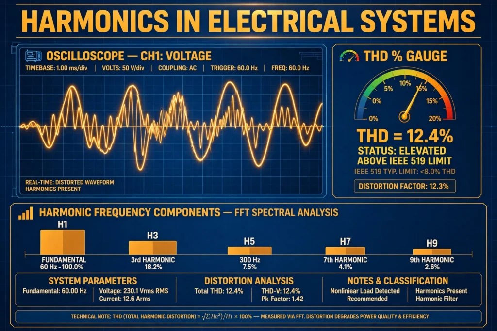

Ideally, the AC power in our homes and factories is a perfect sine wave — smooth, symmetrical, repeating 50 or 60 times per second. In reality, the waveforms in modern electrical systems are rarely perfect. They carry extra ripples riding on top of the fundamental sine wave. These ripples are called harmonics, and they are one of the most common power-quality problems in electrical installations today.
Harmonics waste energy as heat, overload neutral conductors, overheat transformers, trip protective devices for no apparent reason, and shorten equipment life. They come mostly from the electronic loads we now use everywhere: variable frequency drives, computer power supplies, LED lighting, UPS systems, and EV chargers. As power electronics have spread, harmonics have gone from a specialist concern to something every electrical engineer, technician, and facility manager should understand.
This guide explains what harmonics are, what causes them, how total harmonic distortion (THD) is measured, the IEEE 519 limits, the damage harmonics cause, and the practical ways to keep them under control.
What Are Harmonics in Electrical Systems?
A harmonic is a voltage or current component at an integer multiple of the fundamental frequency. If the fundamental is 50 Hz, the 2nd harmonic is 100 Hz, the 3rd is 150 Hz, the 5th is 250 Hz, and so on. (On 60 Hz systems, the 3rd harmonic is 180 Hz, the 5th is 300 Hz, and so forth.)
Any distorted periodic waveform can be broken down into its fundamental plus a series of harmonics — this is the idea behind Fourier analysis. A perfect sine wave contains only the fundamental and has zero harmonics. The more the waveform deviates from a pure sine, the larger its harmonic content.
Harmonics are classified by sequence, which determines how they behave in three-phase systems:
- Positive sequence (1st, 4th, 7th, 10th…): rotate in the same direction as the fundamental and produce forward torque in motors.
- Negative sequence (2nd, 5th, 8th, 11th…): rotate opposite to the fundamental, producing braking torque and extra motor heating.
- Zero sequence (3rd, 6th, 9th, 12th… — the “triplens”): are in phase in all three phases, so instead of cancelling in the neutral conductor, they add up. This is why neutrals in buildings full of computers and LED lighting can carry surprisingly large currents.
What Causes Harmonics? Nonlinear Loads
Harmonics are produced by nonlinear loads — loads whose current is not proportional to the applied voltage. A resistor is a linear load: apply a sine-wave voltage and you get a sine-wave current. But most modern electronic equipment draws current in short pulses rather than a smooth sine wave, and those pulses are rich in harmonics.
The main culprits in a typical facility:
- Variable frequency drives (VFDs): the front-end rectifier of a variable frequency drive draws pulsed current. A standard 6-pulse rectifier generates mainly the 5th, 7th, 11th, and 13th harmonics.
- Switch-mode power supplies: computers, servers, telecom equipment, and phone chargers — all draw current in narrow pulses near the voltage peaks.
- LED lighting and electronic ballasts: millions of small nonlinear loads add up, especially rich in 3rd harmonic (triplen) current.
- UPS systems and battery chargers: rectifier/charger stages distort the input current.
- Welding machines and arc furnaces: highly nonlinear, and arc furnaces also produce non-integer “interharmonics.”
- EV chargers: onboard AC chargers are switch-mode converters; DC fast chargers use large rectifiers.
- Solar inverters: the inverter stage can inject harmonics if poorly filtered.
A useful rule of thumb: a 6-pulse rectifier (the most common industrial type) produces harmonics at orders 6k ± 1 — that is, the 5th, 7th, 11th, 13th, 17th, 19th, and so on. Single-phase electronic loads predominantly produce the 3rd harmonic and other triplens. Problems get worse when many nonlinear loads share one transformer or busbar, because their harmonic currents add together.
Total Harmonic Distortion (THD) Explained
Total harmonic distortion (THD) compresses all the harmonic content of a waveform into a single percentage number. It is defined as the RMS value of all harmonic components divided by the RMS value of the fundamental: THD = sqrt(V2² + V3² + V4² + …) ÷ V1 × 100%
The same formula applies to current (THDi) using the harmonic current components I2, I3, … and the fundamental current I1. A pure sine wave has THD = 0%. A badly distorted waveform can exceed 10% or more.
Worked Example
Suppose a 230 V supply has harmonic voltages of V3 = 8 V, V5 = 6 V, and V7 = 4 V:
- Square each harmonic: 8² = 64, 6² = 36, 4² = 16.
- Sum: 64 + 36 + 16 = 116.
- Square root: sqrt(116) ≈ 10.77 V.
- Divide by the fundamental: 10.77 ÷ 230 ≈ 0.0468.
- THD ≈ 4.7%.
THD vs TDD
For current, engineers often use TDD (total demand distortion) instead of THD. The difference is the denominator: THD divides by the present fundamental current, while TDD divides by the maximum demand current (the facility’s peak load current). This matters because a small load drawing highly distorted current at light load can show an alarming THDi while barely affecting the system — TDD keeps the number meaningful by referencing it to the system’s real capacity.
IEEE 519 Harmonic Limits
IEEE Standard 519 (“Recommended Practice and Requirements for Harmonic Control in Electric Power Systems”) sets the industry’s accepted limits. The key point: it limits voltage distortion at the point of common coupling (PCC) — where the utility meets the customer — and it limits the harmonic current each customer may inject, with stricter current limits for “stiffer” (lower-impedance) systems.
Voltage distortion limits (IEEE 519):
| System voltage | Max voltage THD | Max individual harmonic |
|---|---|---|
| Below 1 kV | 5.0% | 3.0% |
| 1 kV to 69 kV | 3.0% | 2.0% |
| 69.1 kV to 161 kV | 2.5% | 1.5% |
| Above 161 kV | 1.5% | 1.0% |
For most commercial and industrial installations (below 1 kV), the practical target is therefore voltage THD under 5%. Current limits are expressed as TDD and depend on the ratio of short-circuit current to load current at the PCC — the details belong in a dedicated power-quality study, but the 5% voltage THD figure is the number most engineers memorize.
Effects of Harmonics on Equipment
Harmonic currents do no useful work, but they still produce real consequences:
- Transformer overheating: Harmonics increase both winding (I²R) losses and eddy-current losses in the core — and eddy losses rise with the square of frequency, so high-order harmonics are especially damaging. A transformer serving nonlinear loads may need derating or a K-rated design built for harmonic duty. This is one more reason transformer selection matters, as covered in our guide to types of transformers.
- Overloaded neutral conductors: Triplen harmonics (3rd, 9th, 15th…) add arithmetically in the neutral instead of cancelling. In offices full of computers, the neutral can carry current approaching — or even exceeding — phase current, overheating a conductor that was sized assuming balanced linear loads.
- Capacitor bank resonance: Power-factor correction capacitors can resonate with the supply inductance at a harmonic frequency, amplifying that harmonic, overloading the capacitors, and sometimes destroying them. The fix is detuned reactors in series with the capacitors — a detail worth remembering when working on power factor correction.
- Motor heating and vibration: Negative-sequence harmonics create opposing torque, increasing losses and vibration while reducing efficiency. Higher-frequency harmonics add core losses in the laminations.
- Nuisance tripping: Distorted waveforms confuse some protective devices and meters. Thermal-magnetic MCBs may trip early on peak-sensing elements, and zero-sequence currents can cause unwanted earth-fault trips.
- Metering and control errors: Energy meters calibrated for sine waves can misread distorted waveforms, and sensitive electronic controls may malfunction on noisy supplies.
- Skin effect and cable heating: At harmonic frequencies, current crowds toward conductor surfaces, raising effective resistance and heating cables beyond what the fundamental current alone would suggest.
How to Measure Harmonics
You cannot see harmonics with a basic multimeter — you need instruments that analyze the waveform:
- Power quality analyzer: The proper tool. It samples voltage and current waveforms, performs the Fourier decomposition internally, and reports THD, TDD, and the individual harmonic spectrum up to the 50th order or higher. Clamp-on models make field surveys practical.
- True-RMS clamp meter with THD function: Many mid-range clamp meters now display THD for current and voltage — enough for a first-pass check.
- Oscilloscope: Shows the distorted waveform shape directly — good for visualizing the problem.
- Permanent power monitors: Facilities with chronic issues install fixed analyzers that log harmonics continuously and alarm on IEEE 519 violations.
Measure at the point of common coupling for compliance, and at individual load feeders when hunting for the guilty equipment.
How to Reduce Harmonics: Mitigation Methods
Once measurements show a problem, these are the standard fixes, roughly in order of cost and effectiveness:
- Line reactors (AC chokes): Simple inductors placed in series with a VFD or rectifier input. They smooth the current pulses and typically cut THDi by 30–50%. Cheap and very common.
- Passive harmonic filters: Tuned LC circuits that shunt specific harmonic orders (often the 5th and 7th) away from the supply. Effective but must be carefully designed to avoid resonance problems.
- Active harmonic filters (AHF): Power-electronic units that measure the load’s harmonic current in real time and inject an equal-and-opposite waveform, cancelling the harmonics. The most effective solution — can bring THDi below 5% — but also the most expensive.
- 12-pulse (or higher) rectifiers: Using a phase-shifting transformer so two 6-pulse bridges cancel the 5th and 7th harmonics. Common on large drives.
- K-rated or oversized transformers: Do not reduce harmonics, but survive them — K-rated transformers have heavier neutrals and windings designed for harmonic heating.
- Detuned capacitor banks: Adding series reactors to power-factor capacitors so the bank cannot resonate at harmonic frequencies.
- Separate transformers / feeders: Isolating sensitive linear loads from harmonic-producing loads at the distribution level.
- Oversized neutrals: In commercial buildings, neutrals sized at 150–200% of phase conductors handle triplen currents safely.
FAQs
What is the difference between THD and TDD?
THD (total harmonic distortion) expresses harmonic content as a percentage of the current fundamental, while TDD (total demand distortion) uses the maximum demand load current as the reference. TDD is the fairer metric for compliance because it does not exaggerate distortion during light-load periods.
What THD level is acceptable?
For low-voltage systems (below 1 kV), IEEE 519 recommends voltage THD below 5%, with no individual harmonic above 3%. Many facilities aim for current TDD below 5–8% depending on their supply stiffness.
Do harmonics affect the power factor?
Yes — this is called distortion power factor. The familiar displacement power factor (cos φ) only accounts for phase shift; harmonics add a distortion component that lowers the true power factor even when voltage and current fundamentals are perfectly in phase.
Why do LED lights cause harmonics?
LED drivers are switch-mode power supplies that draw current in short pulses near the voltage peaks. Each lamp contributes mainly 3rd-harmonic current; thousands of them in a building add up to significant neutral loading.
Can harmonics damage a transformer?
Absolutely. Harmonic currents increase winding losses and — more severely — eddy-current losses in the core, which grow with the square of frequency. A standard transformer on a heavily nonlinear load can overheat well below its nameplate kVA rating.
What is a K-rated transformer?
A transformer specifically designed to handle harmonic loads: it typically has a 200%-rated neutral, electrostatic shielding, and reduced eddy-current losses. The K-factor (K-4, K-13, K-20…) indicates how much harmonic loading it tolerates.
Conclusion
Harmonics are the invisible tax that nonlinear loads impose on an electrical system. They begin as pulsed currents drawn by drives, power supplies, and chargers, and they end as heat in transformers, overloaded neutrals, resonating capacitor banks, and tripping breakers. The good news is that they are measurable — THD and TDD turn a vague “power quality problem” into hard numbers — and manageable, with IEEE 519 providing clear targets and a well-proven toolkit of reactors, filters, and good design practice.
If your facility runs variable frequency drives, large UPS systems, or extensive LED lighting, a harmonic survey with a power quality analyzer is one of the highest-value measurements you can make. Catching a 12% THDi early — before it cooks a transformer or takes down a capacitor bank — is exactly the kind of preventive engineering that keeps plants running.