
A BLDC motor — short for brushless DC motor — is one of the most important electric motors in modern engineering. It powers drones, electric vehicles, computer cooling fans, washing machines, power tools, and countless industrial machines. Despite the name, it runs on DC power yet behaves in many ways like a three-phase AC motor, and it achieves this with no brushes at all.
The “brushless” part is the key innovation. A traditional brushed DC motor uses carbon brushes rubbing against a rotating commutator to switch current direction in the windings. Those brushes wear out, spark, create electrical noise, and limit speed and lifespan. A BLDC motor eliminates them entirely and replaces the mechanical switching with electronic commutation — a controller that energizes the windings in the right sequence at exactly the right moment. The result is a motor that is more efficient, quieter, longer-lasting, and far better suited to precise speed control.
In this guide, you will learn what a BLDC motor is, how it is built, how electronic commutation works, how the controller knows the rotor’s position, the different control methods, the main types, and where these motors are used every day.
What Is a BLDC Motor?
A BLDC motor is a DC-powered electric motor in which the rotor carries permanent magnets and the stator carries the windings. This is the reverse of a brushed DC motor, where the windings sit on the rotor and the magnets (or field windings) sit on the stator. Because the windings are stationary, there is no need to transfer current to a rotating part — and therefore no need for brushes or a commutator.
The stator is typically wound in a three-phase arrangement, very much like a small three-phase AC motor. The rotor contains permanent magnets arranged with alternating north and south poles around its circumference. When the stator windings are energized in sequence, they create a rotating magnetic field that pulls the rotor’s magnets around with it, producing torque.
The catch is that the switching must be perfectly timed with the rotor’s position. That timing job belongs to the electronic speed controller (ESC) — a dedicated drive circuit, usually built around power MOSFETs or IGBTs, that reads rotor position feedback and fires the correct winding pair at each instant. If you have ever wondered how a variable frequency drive controls an AC motor’s speed electronically, a BLDC controller works on the same family of ideas, just optimized for a DC supply.
Construction of a BLDC Motor
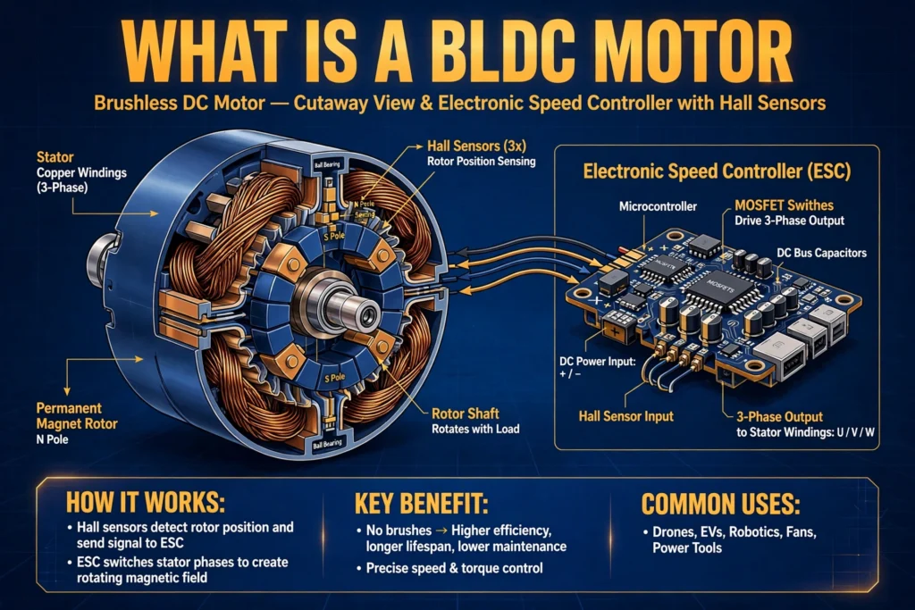
Understanding the parts makes the working principle much clearer:
- Stator: A laminated steel core with slots holding the copper windings. Most BLDC motors use three-phase windings (phases A, B, and C) connected in star (wye) configuration. The laminations — thin insulated steel sheets — keep eddy-current losses low.
- Rotor: A shaft-mounted assembly carrying permanent magnets, usually made from high-strength materials like neodymium-iron-boron. The number of magnetic pole pairs determines the relationship between electrical and mechanical speed: one mechanical revolution equals as many electrical cycles as there are pole pairs.
- Hall effect sensors: Three sensors mounted 120 degrees apart in the stator switch as the rotor poles pass over them, changing state every 60 electrical degrees — six unique combinations per cycle, exactly matching the six commutation steps.
- Electronic controller: The drive that switches the DC supply across the phases in sequence, controls speed via PWM, and provides protection like overcurrent shutdown.
- Bearings and housing: Since there are no brushes to service, the bearings are typically the only wearing mechanical part — which is why BLDC motors routinely outlast brushed motors by a wide margin.
Working Principle: Electronic Commutation
The working principle of a BLDC motor is electronic commutation — the controller’s job of energizing the right stator coils at the right time to keep the rotor turning.
Here is the simplified sequence for the most common drive method, called six-step (trapezoidal) commutation:
- The three-phase stator has six distinct switching states per electrical cycle. In each state, the controller energizes two of the three phases — one connected to the positive supply, one to the negative — while the third phase floats.
- The energized phases create a stator field that pulls the rotor’s magnets toward alignment, so the rotor turns.
- Just before the rotor would “catch up” and lock into alignment (which would stop the motor), the Hall sensors signal the controller that the rotor has moved 60 electrical degrees.
- The controller switches to the next state, advancing the stator field another 60 degrees ahead of the rotor.
- This repeats six times per electrical cycle, producing continuous rotation. Speed is controlled by varying the average voltage applied to the windings, almost always with pulse-width modulation (PWM); torque is controlled by the current.
Because only two inverter switches conduct at any instant and the switching follows the rotor, the motor always produces torque in the same direction. The back EMF (the voltage the spinning magnets induce in the windings) has a trapezoidal waveform in a true BLDC motor — which is why this drive method is also called trapezoidal commutation.
Rotor Position Sensing: Hall Sensors vs Sensorless
The controller cannot commutate correctly without knowing where the rotor is. There are two approaches:
Sensored: Hall Effect Sensors
Three Hall sensors mounted 120 degrees apart in the stator switch on and off as the rotor’s north and south poles pass over them. Their three binary outputs change state every 60 electrical degrees, giving six unique combinations per electrical cycle — exactly matching the six commutation steps. The controller simply looks up which winding pair to energize for each Hall pattern.
Hall-sensor control is simple, cheap, and gives reliable starting torque even from a standstill, which is why it dominates in e-bikes, power tools, and appliances. Its weakness is resolution: with position updates only every 60 degrees, motion is slightly rough, and the sensors add wiring and a potential failure point inside the motor.
Sensorless: Back-EMF Detection
In the sensorless method, the controller watches the unenergized third phase and detects the instant its back EMF crosses zero, revealing rotor position with no physical sensors. This means cheaper builds and fewer wires — which is why most drone and RC hobby motors use it.
The trade-off is starting: at zero speed there is no back EMF to measure, so sensorless controllers start the motor “blind” with a pre-programmed ramp until the signal becomes readable. Under sudden heavy load the estimated position can momentarily go wrong and stall the motor, so applications needing guaranteed starting torque still prefer sensored control.
Control Methods: Trapezoidal, Sinusoidal, and FOC
Beyond the basic six-step drive, two more refined methods exist:
- Trapezoidal (six-step) commutation: The simplest method — two phases on, one off, switching every 60 degrees. It is cheap and works well at high speed, but the abrupt current steps create torque ripple and audible noise, and low-speed smoothness is poor.
- Sinusoidal commutation: All three phases are energized continuously with sinusoidal currents shifted 120 degrees apart, matched to rotor angle. Torque ripple nearly disappears and motion becomes smooth and quiet — ideal for precise low-speed positioning. It needs accurate rotor position feedback (an encoder or resolver rather than basic Hall sensors) and a more capable controller.
- Field-oriented control (FOC): The most advanced method. It mathematically transforms the three-phase currents into a rotating reference frame (using Clarke and Park transforms) and controls torque and magnetic flux as two independent DC-like quantities. FOC delivers maximum efficiency, the smoothest torque, and excellent dynamic response at any speed — at the cost of the most complex firmware and the need for high-resolution position feedback.
In practice, trapezoidal drives serve fans, pumps, and tools; sinusoidal and FOC drives serve robotics, EVs, CNC machines, and anywhere smooth, efficient motion matters.
Types of BLDC Motors
BLDC motors are classified in two useful ways:
By Rotor Construction: Inrunner vs Outrunner
- Inrunner: The permanent-magnet rotor spins inside the stator windings, like a conventional motor. Inrunners reach very high RPM and are common in power tools, RC cars, and spindles.
- Outrunner: The rotor (with magnets on its inner surface) spins outside the stator, and the motor’s outer case itself rotates. Outrunners produce more torque at lower RPM and are the standard choice for drone propellers, e-bike hub motors, and ceiling fans.
By Feedback: Sensored vs Sensorless
As covered above, sensored motors carry Hall sensors for reliable startup and low-speed control, while sensorless motors rely on back-EMF detection and need simpler wiring. Many controllers can run either type.
BLDC vs Brushed DC vs PMSM
| Feature | Brushed DC | BLDC | PMSM |
|---|---|---|---|
| Commutation | Mechanical (brushes) | Electronic | Electronic |
| Rotor | Windings | Permanent magnets | Permanent magnets |
| Back EMF shape | — | Trapezoidal | Sinusoidal |
| Drive waveform | DC | Six-step / trapezoidal | Sinusoidal |
| Torque ripple | Low | Noticeable | Very low |
| Maintenance | Brush replacement | Bearings only | Bearings only |
| Efficiency | 75–80% | 85–90% | 90–95% |
| Cost | Lowest | Medium | Highest |
Advantages and Disadvantages
Advantages: no brush wear or sparking (long life, safe in explosive atmospheres); high efficiency (85–90%+); excellent speed control range; high power-to-weight ratio; quiet operation; low electromagnetic interference; compact size for the torque produced.
Disadvantages: needs an electronic controller (higher system cost than a brushed motor); sensorless versions can struggle at startup; more complex to repair.
Applications of BLDC Motors
- Electric vehicles and e-bikes: hub motors and traction motors prized for efficiency and regenerative braking compatibility.
- Drones and RC aircraft: lightweight outrunners with sensorless controllers.
- HVAC and appliances: variable-speed compressor and fan motors in air conditioners, refrigerators, and washing machines — major energy savers.
- Power tools: cordless drills and saws, where high torque density extends battery runtime.
- Industrial automation: conveyor drives, pumps, and robotics, often commanded by a PLC for precise motion sequences.
- Medical and IT equipment: ventilators, centrifuges, and cooling fans where quiet, reliable, long-life operation is essential.
- Computer peripherals: hard-disk spindle motors and cooling fans — some of the earliest mass-market BLDC applications.
FAQs
Why is it called “brushless DC” if the controller uses AC-like switching?
Because the supply is DC and its torque–speed behavior resembles a DC motor — even though the controller synthesizes an AC-like rotating field internally.
Can a BLDC motor run without a controller?
No. A brushed motor spins when you connect a battery, but a BLDC motor is useless without its controller — it performs the commutation the brushes used to do.
What is the difference between a BLDC motor and a stepper motor?
A stepper motor moves in discrete steps and is designed for precise positioning, usually at low speed. A BLDC motor is designed for continuous smooth rotation with high efficiency. Both are brushless and electronically commutated, but their construction and control goals differ.
Do BLDC motors need maintenance?
Very little. With no brushes to wear out, the only routine wear items are the bearings. Quality BLDC motors commonly exceed 10,000–20,000 hours of service, several times the life of a brushed equivalent.
Why do BLDC motors use Hall sensors?
The controller must energize each winding at exactly the right rotor angle. Hall sensors report the rotor’s position in 60-degree increments, letting the controller pick the correct commutation step — simple, cheap, and reliable, especially at startup.
Are BLDC motors more efficient than induction motors?
Generally yes at small sizes: with no rotor copper losses (the rotor field comes from permanent magnets), small BLDC motors typically reach 85–90%+ efficiency — noticeably above small single-phase induction motors.
Conclusion
A BLDC motor earns its place by doing away with the weakest part of the classic DC motor — the brushes — and replacing it with intelligent electronics. Permanent magnets on the rotor, three-phase windings on the stator, Hall-sensor or sensorless position feedback, and a six-step (or more advanced) controller work together to deliver efficient, quiet, long-lasting motion.
Whether it is spinning a drone propeller, driving an e-bike wheel, or running a factory conveyor under PLC control, the BLDC motor’s combination of efficiency and controllability keeps it at the heart of modern electrification.