Imagine electricity generated at a power plant at 11 kV. It cannot be transmitted directly over long distances at this voltage because losses will be high. So, engineers use a transformer to increase the voltage to 132 kV or even higher. Near your home, another transformer reduces that high voltage to 230V so you can safely use fans, lights, and appliances.
This simple example shows how important transformers are in our daily life. Without them, modern power systems would not work efficiently or safely.
Understanding the types of transformers is essential for electrical students, engineers, technicians, and beginners. Different applications require different transformer designs. In this detailed guide, you will learn the types of transformers, transformer working principle, classification, components, applications, advantages and disadvantages, and practical selection tips — explained in simple and clear English.
What is Types of Transformers?
A transformer is an electrical device that transfers electrical energy from one circuit to another using electromagnetic induction. It can increase or decrease voltage without changing frequency.
When we talk about types of transformers, we mean different transformer designs based on function, construction, voltage level, cooling method, and application.
Simple Explanation
A transformer changes voltage level:
- High voltage to low voltage (step-down)
- Low voltage to high voltage (step-up)
It works only with alternating current (AC).
Practical Example
In a mobile charger, a small transformer reduces 230V AC to a lower voltage before rectification. In a power station, a large transformer increases generator voltage for transmission.
Transformer Working Principle
The transformer working principle is based on electromagnetic induction.
Let’s understand step-by-step with a simple analogy.
Think of two coils placed near each other. When electricity flows in the first coil, it creates a magnetic field. That magnetic field links to the second coil and produces voltage.
Step-by-Step Process
- AC supply applied to primary winding
- Current flows in primary coil
- Magnetic field is produced in core
- Magnetic field links secondary coil
- Voltage is induced in secondary winding
Important Points
- Works only with AC
- No direct electrical connection between windings
- Voltage ratio depends on number of turns
If primary turns are more than secondary, voltage decreases.
If secondary turns are more than primary, voltage increases.
This is the basic transformer working principle.
Types / Classification of Transformers
Transformers can be classified in many ways. Let’s understand each type clearly.
Based on Voltage Level
Step-Up Transformer
A step-up transformer is an electrical device used to increase (or “step up”) the voltage level of an alternating current (AC) supply while decreasing the current proportionally. It is widely used in power transmission systems to efficiently send electricity over long distances. The basic working principle of a step-up transformer is based on Mutual Induction, where a changing current in one coil produces a magnetic field that induces voltage in another coil.
A step-up transformer mainly consists of two windings: the primary winding and the secondary winding, both wound around a common magnetic core made of laminated iron. When an AC voltage is applied to the primary winding, it creates an alternating magnetic flux in the core. This flux links with the secondary winding and induces a voltage in it. In a step-up transformer, the number of turns in the secondary winding is greater than the number of turns in the primary winding. Because of this turns ratio, the voltage in the secondary side becomes higher than the primary voltage. The relationship between voltage and turns is given by the transformer equation: V₂/V₁ = N₂/N₁, where V is voltage and N is the number of turns.
One of the most important applications of a step-up transformer is in power generation stations. After electricity is generated at a relatively low voltage, it is stepped up to very high voltage levels before being transmitted through transmission lines. This reduces current and minimizes power losses due to resistance in the lines, making the system more efficient. Step-up transformers are also used in devices like inverters, UPS systems, and industrial equipment where higher voltage is required.
The advantages of a step-up transformer include high efficiency, reduced transmission losses, and reliable operation. It has no moving parts, which makes it durable and requires low maintenance. However, it also has some limitations. It works only with AC supply and cannot operate with direct current (DC). Also, proper insulation and cooling are required to handle high voltages safely.
Overall, a step-up transformer is a vital component in modern electrical systems. It plays a key role in power transmission and distribution by increasing voltage levels, improving efficiency, and ensuring that electricity can be delivered safely and economically over long distances.
- Increases voltage
- Used in power generation stations
- Secondary turns > Primary turns
Step-Down Transformer
A step-down transformer is an electrical device used to reduce (or “step down”) the voltage level of an alternating current (AC) supply while increasing the current proportionally. It is commonly used in homes, industries, and electronic devices where lower voltage is required for safe and efficient operation. The working principle of a step-down transformer is based on Mutual Induction, where a changing current in one coil produces a magnetic field that induces voltage in another coil.
A step-down transformer consists of two main windings: the primary winding and the secondary winding, both wound on a laminated iron core. When an AC voltage is applied to the primary winding, it creates an alternating magnetic flux in the core. This magnetic flux links with the secondary winding and induces a voltage in it. In this type of transformer, the number of turns in the secondary winding is less than the number of turns in the primary winding. Due to this difference in turns ratio, the voltage at the secondary side is lower than the primary voltage, while the current increases accordingly. The relationship between voltage and turns is given by the transformer formula: V₂/V₁ = N₂/N₁.
Step-down transformers are widely used in distribution systems. After electricity travels through transmission lines at high voltage, it is reduced to safer levels before being supplied to homes and commercial buildings. For example, high transmission voltages are stepped down to 220V or 110V for domestic use. They are also used in chargers, adapters, welding machines, and electronic circuits where specific low voltage is required.
The advantages of a step-down transformer include safe voltage levels, efficient operation, and long service life. It has a simple design with no moving parts, which reduces maintenance needs. However, it also has some limitations. It works only with AC supply and cannot operate with DC. Additionally, improper loading or overheating can reduce its efficiency.
Overall, a step-down transformer is an essential device in electrical systems. It ensures that high voltage power is converted into usable and safe levels, making it suitable for everyday applications in homes and industries.
- Decreases voltage
- Used in distribution systems
- Primary turns > Secondary turns
Based on Construction
Core-Type Transformer
A core-type transformer is a type of transformer in which the windings are placed around the two limbs of the magnetic core. In this design, the core forms a rectangular frame, and both the primary and secondary windings are wound on separate limbs of the core. It is one of the most commonly used transformer constructions in electrical systems due to its simple design, efficient cooling, and ease of maintenance. The working principle of a core-type transformer is based on Mutual Induction, where a changing current in the primary winding produces a magnetic flux that induces voltage in the secondary winding.
In a core-type transformer, the magnetic core is made of laminated silicon steel sheets to reduce energy losses due to eddy currents and hysteresis. The primary winding is connected to the input AC supply, while the secondary winding delivers the output voltage. When AC current flows through the primary winding, it generates an alternating magnetic flux in the core. This flux passes through both limbs of the core and links with the secondary winding, inducing an electromotive force (EMF). The voltage induced in the secondary winding depends on the turns ratio between the primary and secondary coils.
One of the key advantages of a core-type transformer is its good heat dissipation. Since the windings are exposed on the outer parts of the core, cooling becomes easier, which improves efficiency and performance. It also allows easy inspection and repair of windings. Additionally, this type of transformer requires less core material compared to some other designs, making it cost-effective.
However, there are some disadvantages as well. The windings are more exposed, so they require better insulation and protection from external damage. Also, mechanical strength is slightly lower compared to shell-type transformers.
Overall, a core-type transformer is a reliable and widely used design in power distribution and electrical applications. Its simple construction, efficient performance, and ease of maintenance make it suitable for both small and large-scale transformer systems.
- Windings placed around the core
- Simple construction
- Easy maintenance
Shell-Type Transformer
A shell-type transformer is a type of transformer in which the magnetic core surrounds the windings, forming a protective “shell” around them. In this design, both the primary and secondary windings are placed on the central limb of the core, while the magnetic flux flows through two outer limbs, creating a double magnetic path. This structure provides better mechanical strength and improved magnetic performance compared to some other transformer designs. The working principle of a shell-type transformer is based on Mutual Induction, where a changing current in the primary winding produces a magnetic field that induces voltage in the secondary winding.
The core of a shell-type transformer is made of laminated silicon steel sheets to reduce energy losses such as eddy current and hysteresis losses. The windings are usually arranged in a sandwich or interleaved form, where layers of primary and secondary coils are placed alternately. This arrangement improves coupling between the windings and reduces leakage flux, resulting in better efficiency and voltage regulation. Since the windings are enclosed within the core, they are well protected from external damage and environmental effects.
One of the main advantages of a shell-type transformer is its strong mechanical construction and better protection of windings. It also has lower leakage reactance and improved performance under heavy loads. Additionally, the compact design makes it suitable for high-power and high-voltage applications. However, there are some disadvantages as well. The construction is more complex compared to a core-type transformer, and cooling is relatively difficult because the windings are enclosed within the core. Maintenance and repair can also be more challenging.
Overall, a shell-type transformer is widely used in power systems where high efficiency, strength, and reliability are required. Its robust design, better magnetic coupling, and improved performance make it suitable for industrial and heavy-duty electrical applications.
- Core surrounds the windings
- Better mechanical strength
- Used in high-voltage applications
Based on Application
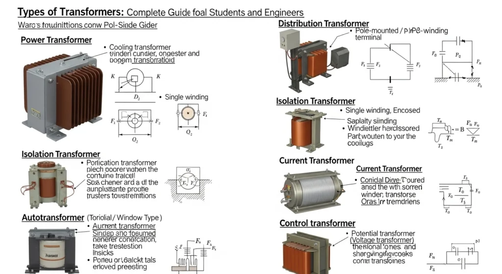
Power Transformer
A power transformer is a high-capacity electrical device used in power generation and transmission systems to transfer electrical energy between circuits at different voltage levels. It is mainly designed to operate at high voltages (above 33 kV) and is used in power stations and transmission networks. The main purpose of a power transformer is to step up the voltage for long-distance transmission or step it down for distribution. Its working principle is based on Mutual Induction, where a changing magnetic field in the primary winding induces voltage in the secondary winding.
A power transformer consists of a laminated steel core, primary winding, secondary winding, insulation system, and cooling system. The core provides a path for magnetic flux, while the windings carry electrical current. When alternating current flows through the primary winding, it creates a magnetic field that induces voltage in the secondary winding. The voltage level depends on the turns ratio between the windings. Power transformers are designed to operate efficiently at full load for long periods, which makes them different from distribution transformers that work under varying loads.
One of the most important features of a power transformer is its high efficiency, usually above 95–99%, because it is designed to minimize energy losses. It uses advanced cooling methods such as oil cooling, air cooling, or forced cooling systems to handle heat generated during operation. These transformers are typically installed in power stations, substations, and grid networks where large amounts of electrical energy are handled.
The advantages of a power transformer include high efficiency, reliable operation, and ability to handle large voltage and power levels. It plays a key role in reducing transmission losses and ensuring stable power supply over long distances. However, it also has some disadvantages. It is large in size, expensive to install, and requires regular maintenance and protection systems to ensure safe operation.
Overall, a power transformer is an essential component of the electrical power system. It enables efficient transmission and distribution of electricity, ensuring that power generated at plants reaches consumers safely and effectively.
- Used in transmission network
- High voltage and high power
- Installed in substations
Distribution Transformer
A distribution transformer is an electrical device used to step down high voltage electricity to a lower voltage level that can be safely used in homes, offices, shops, and small industries. It is an important part of the power distribution system and is usually installed near residential or commercial areas. The main function of a distribution transformer is to provide the final voltage transformation before electricity reaches the consumer. Its working principle is based on Mutual Induction, where a changing magnetic field in the primary winding induces voltage in the secondary winding.
A distribution transformer consists of a laminated steel core, primary winding, secondary winding, insulation system, and cooling arrangement. The primary winding receives high voltage from the transmission or sub-transmission system, while the secondary winding delivers reduced voltage suitable for end users (such as 415V or 230V). These transformers are designed to operate at low load conditions for most of the time, with high efficiency at partial loads. They are commonly oil-immersed or dry-type, depending on the application and installation environment.
One of the key features of a distribution transformer is its ability to provide stable and safe voltage supply to consumers. It ensures that electrical appliances receive the correct voltage level, preventing damage and improving performance. These transformers are usually installed on poles, ground-mounted substations, or inside buildings. They are designed for continuous operation with minimal maintenance requirements.
The advantages of distribution transformers include high efficiency at low loads, reliable performance, and long service life. They help reduce voltage from transmission levels to usable levels, making electricity safe for everyday use. However, they also have some limitations. They are not designed for heavy overloads and may suffer from losses if not properly maintained. Overheating and insulation failure can also occur if load conditions are not properly managed.
Overall, a distribution transformer plays a vital role in the electrical power system. It ensures safe, efficient, and reliable delivery of electricity from the grid to consumers, making it an essential component of modern power distribution networks.
- Used near consumer areas
- Lower voltage levels
- Smaller size compared to power transformer
Instrument Transformer
An instrument transformer is a special type of transformer used in electrical power systems to measure high voltage and high current safely. It is designed to step down these large electrical quantities to a lower, manageable value that can be easily measured by standard instruments like voltmeters, ammeters, wattmeters, and energy meters. Instrument transformers are mainly used for protection and measurement purposes in substations and power systems. Their working principle is based on Mutual Induction, where a changing magnetic field in the primary winding induces a proportional voltage or current in the secondary winding.
There are two main types of instrument transformers: Current Transformer (CT) and Potential Transformer (PT) or Voltage Transformer (VT). A current transformer reduces high current values to a standard low current (usually 5A or 1A) so that measuring instruments can safely read the current in the circuit. On the other hand, a potential transformer reduces high voltage to a standard low voltage (such as 110V) for measurement and protection devices. Both types ensure safety by isolating the measuring instruments from the high-voltage power system.
Instrument transformers are made using a magnetic core, primary winding, and secondary winding. The primary winding is connected to the high-voltage circuit, while the secondary winding is connected to measuring or protection devices. These transformers are designed with high accuracy so that the measurements are reliable and precise. They also provide electrical isolation, which protects both equipment and operators from dangerous high voltages.
One of the major advantages of instrument transformers is safety. They allow engineers and technicians to measure high electrical values without direct exposure to dangerous voltages and currents. They also improve accuracy in measurement and are essential for protective relays that detect faults in the system. However, they must be used carefully, as incorrect connection or open-circuit operation of a current transformer can be hazardous.
Overall, instrument transformers are essential components in modern power systems. They ensure safe monitoring, accurate measurement, and effective protection of electrical networks, making them highly important in power generation, transmission, and distribution systems.
Used for measurement and protection.
Current Transformer (CT)
A Current Transformer (CT) is a type of instrument transformer used to measure high alternating current (AC) in power systems safely. It reduces large current values to a small, standardized value that can be easily measured by instruments like ammeters and used in protective relays. The main purpose of a CT is to ensure safe monitoring and protection of electrical systems without directly connecting measuring devices to high-current lines. Its working principle is based on Mutual Induction, where current in the primary winding produces a magnetic field that induces a proportional current in the secondary winding.
A current transformer has two windings: the primary winding and the secondary winding. The primary winding is usually connected in series with the power line and carries the actual high current. The secondary winding is connected to measuring instruments or protection devices and produces a reduced current, typically 5A or 1A. The ratio between primary and secondary current depends on the number of turns in the windings. For example, a CT with a ratio of 1000:5 means that when 1000A flows in the primary, 5A flows in the secondary.
One of the most important features of a CT is safety. It isolates high-voltage circuits from measuring equipment, protecting both instruments and operators. CTs are widely used in substations, power plants, and industrial electrical systems for monitoring load current and detecting faults. They also play a key role in protective relays that help disconnect faulty circuits and prevent damage to equipment.
The advantages of current transformers include high accuracy, safe operation, and ability to handle very high currents. They are compact and reliable, making them suitable for modern power systems. However, there is an important safety precaution: the secondary of a CT should never be left open while the primary is energized, as it can generate dangerously high voltage.
Overall, a Current Transformer is an essential device in electrical engineering. It ensures safe current measurement, reliable system protection, and efficient monitoring of power systems in generation, transmission, and distribution networks.
Potential Transformer (PT)
A Potential Transformer (PT), also known as a Voltage Transformer (VT), is an instrument transformer used to measure high alternating voltage safely in power systems. It steps down high voltage levels to a low, standardized voltage that can be easily measured by voltmeters, wattmeters, energy meters, and protection relays. The main purpose of a PT is to provide accurate voltage measurement and electrical isolation between high-voltage power circuits and measuring instruments. Its working principle is based on Mutual Induction, where a changing magnetic field in the primary winding induces a proportional voltage in the secondary winding.
A potential transformer consists of a primary winding connected across the high-voltage line and a secondary winding connected to measuring or protection devices. The primary winding handles the high voltage, while the secondary winding produces a reduced and safe voltage, usually 110V or 63.5V depending on the system. The voltage ratio between primary and secondary depends on the number of turns in the windings. For example, a PT with a ratio of 11kV/110V reduces 11,000 volts to 110 volts for safe measurement.
One of the most important functions of a PT is safety. It isolates high-voltage circuits from operators and instruments, preventing electrical hazards. It also ensures accurate voltage measurement, which is essential for proper monitoring and control of electrical power systems. PTs are widely used in substations, power plants, and industrial electrical systems for metering and protection purposes.
The advantages of potential transformers include high accuracy, reliable performance, and safe operation. They allow sensitive measuring devices to work without direct exposure to high voltage. However, they must be properly rated and installed, as incorrect usage can affect measurement accuracy and system safety.
Overall, a Potential Transformer is a vital component in electrical engineering. It ensures safe voltage measurement, system protection, and accurate monitoring in power generation, transmission, and distribution networks.
These reduce high current or voltage to safe levels for meters and relays.
Based on Cooling Method
Oil-Immersed Transformer
An oil-immersed transformer is a type of transformer in which the core and windings are completely submerged in insulating oil inside a sealed tank. This oil acts as both an insulator and a cooling medium, helping the transformer operate safely and efficiently under high load conditions. It is widely used in power stations, substations, and industrial applications where large amounts of electrical energy need to be handled. The working principle of an oil-immersed transformer is based on Mutual Induction, where alternating current in the primary winding produces a magnetic field that induces voltage in the secondary winding.
The main components of an oil-immersed transformer include the magnetic core, primary winding, secondary winding, insulating oil, and tank. The transformer oil plays a very important role. It provides insulation between live parts and also removes heat generated during operation. When the transformer is under load, heat is produced in the windings and core. The oil absorbs this heat and transfers it to the outer tank surface, where it is dissipated into the surrounding air. In large transformers, cooling radiators and fans are also used to improve heat dissipation.
One of the biggest advantages of an oil-immersed transformer is its high efficiency and excellent cooling capability. The oil prevents overheating and increases the life of the transformer. It also provides strong insulation, allowing the transformer to handle high voltages safely. These transformers are reliable and suitable for continuous heavy-duty operation. However, they also have some disadvantages. They require regular maintenance, and there is a risk of oil leakage or fire if not properly maintained. The oil can also degrade over time and needs testing or replacement.
Overall, oil-immersed transformers are essential in modern power systems. Their strong insulation, effective cooling, and ability to handle high power levels make them a preferred choice for large-scale electrical transmission and distribution networks.
- Windings immersed in oil
- Oil provides cooling and insulation
- Used in large power systems
Dry-Type Transformer
A dry-type transformer is a type of transformer that does not use any liquid such as oil for cooling or insulation. Instead, it uses air and solid insulation materials like epoxy resin to protect the core and windings. This makes it safer and more environmentally friendly compared to oil-filled transformers. Dry-type transformers are commonly used in buildings, hospitals, shopping malls, metro stations, and industrial plants where fire safety is very important. The working principle of a dry-type transformer is based on Mutual Induction, where alternating current in the primary winding creates a magnetic field that induces voltage in the secondary winding.
In a dry-type transformer, the core is made of laminated silicon steel to reduce losses, and the windings are insulated using materials like varnish or epoxy resin. The primary winding receives input voltage, while the secondary winding delivers the required output voltage. Since there is no oil, the heat generated during operation is removed by natural air circulation or forced air cooling using fans. This makes the transformer simpler in design and easier to install indoors.
One of the main advantages of a dry-type transformer is its high safety level. Since it does not contain oil, there is no risk of fire or oil leakage, making it suitable for indoor and sensitive environments. It also requires less maintenance and is more environmentally friendly. Additionally, it has good performance in polluted or humid areas because it is sealed and protected from moisture and dust.
However, dry-type transformers also have some limitations. Their cooling efficiency is lower compared to oil-immersed transformers, so they are usually used for lower to medium power ratings. They can also be more expensive for the same capacity.
Overall, a dry-type transformer is a safe, reliable, and eco-friendly solution for modern electrical systems, especially in places where fire safety and clean operation are important.
- Air-cooled
- Used indoors
- Low maintenance
Based on Phases
Single-Phase Transformer
A single-phase transformer is an electrical device used to transfer electrical energy between two circuits using a single alternating current (AC) phase. It is mainly used to step up or step down voltage levels in residential, commercial, and light industrial applications. The basic working principle of a single-phase transformer is based on Mutual Induction, where a changing current in the primary winding creates a magnetic field that induces voltage in the secondary winding.
A single-phase transformer consists of a laminated iron core, primary winding, and secondary winding. The primary winding is connected to the AC supply, while the secondary winding delivers the output voltage. When AC current flows through the primary coil, it produces an alternating magnetic flux in the core. This flux links both windings and induces an electromotive force (EMF) in the secondary winding. The voltage transformation depends on the turns ratio between the primary and secondary coils. If the secondary has more turns than the primary, the voltage increases (step-up), and if it has fewer turns, the voltage decreases (step-down).
One of the key advantages of a single-phase transformer is its simple design and easy installation. It is compact, cost-effective, and requires low maintenance. These transformers are commonly used in household power supply systems, small electronic devices, lighting systems, and low-power applications. They are also used in rural electrification where power demand is relatively low.
However, there are some limitations. A single-phase transformer is not suitable for heavy industrial loads or large power transmission systems. It has lower efficiency compared to three-phase transformers when used for high-power applications. Also, it is less stable for large-scale power distribution.
Overall, a single-phase transformer is an essential and widely used electrical device. It provides safe and efficient voltage conversion for everyday applications, making it a key component in modern electrical distribution systems.
- Used in homes
- Small load applications
Three-Phase Transformer
A three-phase transformer is an electrical device used to transfer electrical energy between two three-phase systems at different voltage levels. It is widely used in power generation, transmission, and industrial applications where large amounts of electricity are required. The main purpose of a three-phase transformer is to step up or step down voltage in a three-phase power system while maintaining efficiency and stability. Its working principle is based on Mutual Induction, where a changing magnetic field in the primary windings induces voltage in the secondary windings.
A three-phase transformer can be constructed in two main ways: either by combining three single-phase transformers or by using a single unit with a shared magnetic core. It consists of primary and secondary windings for each phase, arranged on a laminated iron core. When a three-phase AC supply is given to the primary windings, it produces a rotating magnetic field in the core. This magnetic field induces voltage in the secondary windings, providing three-phase output at the required voltage level. The voltage transformation depends on the turns ratio of the windings.
One of the main advantages of a three-phase transformer is its high efficiency and ability to handle large power loads. It is more economical and compact compared to using three separate single-phase transformers. It also provides better voltage regulation and smoother power delivery, which is important for industrial machines and large electrical systems. These transformers are commonly used in power stations, substations, manufacturing plants, and heavy industries.
However, there are some disadvantages as well. Three-phase transformers are more complex in design and require careful installation and maintenance. If one phase fails, it can affect the entire system. They are also more expensive than single-phase transformers for small-scale applications.
Overall, a three-phase transformer is a crucial component in modern power systems. It ensures efficient, stable, and large-scale transmission and distribution of electrical energy, making it essential for industrial and utility-level power networks.
- Used in industries
- High power applications
Based on Special Purpose
Auto Transformer
An auto transformer is a type of electrical transformer in which both primary and secondary windings are connected in a single continuous winding. Unlike conventional transformers, it does not have separate primary and secondary coils. Instead, a portion of the same winding acts as both primary and secondary, depending on the connection point. It is commonly used to step up or step down voltage levels efficiently in power systems, industrial applications, and motor starting systems. The working principle of an auto transformer is based on Mutual Induction, where a changing magnetic field in the winding induces voltage along different sections of the same coil.
In an auto transformer, the single winding is tapped at different points to provide required voltage levels. When AC voltage is applied, current flows through the winding and creates a magnetic flux in the core. This flux induces voltage across different parts of the same winding. Depending on the tap position, the output voltage can be higher or lower than the input voltage. If the output is taken from a portion of the winding, it acts as a step-down transformer, and if taken from the full winding, it can act as a step-up transformer.
One of the major advantages of an auto transformer is its high efficiency because it uses less copper and has lower losses compared to conventional transformers. It is also smaller, lighter, and more cost-effective for the same power rating. Auto transformers provide better voltage regulation and are commonly used in applications like voltage control, induction motor starting, and interconnecting systems with small voltage differences.
However, there are some limitations. The main disadvantage is the lack of electrical isolation between primary and secondary sides, which can be a safety risk. Also, if a fault occurs, it can directly affect both sides of the circuit. Because of this, auto transformers are not suitable for all applications, especially where isolation is required.
Overall, an auto transformer is an efficient and economical solution for voltage control and power transfer. Its simple design, reduced material usage, and high performance make it useful in many industrial and electrical engineering applications.
- Single winding
- Smaller size
- Used in voltage regulation
Isolation Transformer
An isolation transformer is a special type of transformer designed to provide electrical isolation between the primary (input) and secondary (output) circuits while maintaining the same voltage level. Its main purpose is to improve safety and protect equipment and users from electric shock, noise, and voltage disturbances. The working principle of an isolation transformer is based on Mutual Induction, where electrical energy is transferred from one coil to another through a magnetic field without direct electrical connection.
An isolation transformer consists of a primary winding and a secondary winding wound separately on a laminated iron core. When alternating current flows through the primary winding, it produces a changing magnetic flux in the core. This flux induces an equal voltage in the secondary winding. In most cases, the input and output voltages are the same (for example, 230V to 230V), but the key feature is galvanic isolation, meaning there is no direct electrical path between the two sides. This separation helps to prevent electric shock and reduces the risk of damage from faults.
One of the major advantages of an isolation transformer is safety. It protects users from direct contact with live electrical circuits. It also helps reduce electrical noise, voltage spikes, and interference, making it very useful for sensitive electronic equipment like medical devices, laboratory instruments, and communication systems. Isolation transformers are also used in industrial environments to protect control circuits and improve system stability.
However, there are some limitations. Isolation transformers are generally bulkier and more expensive than standard transformers of the same rating. They also do not change voltage levels unless specifically designed to do so. Additionally, they still require proper installation and maintenance to ensure safe operation.
Overall, an isolation transformer is an important safety device in electrical systems. It provides electrical separation, enhances protection, and improves the reliability of sensitive equipment, making it essential in both industrial and critical applications.
- Provides electrical isolation
- Used for safety
Understanding the difference between power transformer and distribution transformer is important for exams and practical field work.
Main Components of a Transformer
Every transformer has important parts.
Core
- Made of laminated silicon steel
- Provides magnetic path
- Reduces losses
Primary Winding
- Connected to input supply
- Produces magnetic field
Secondary Winding
- Delivers output voltage
- Receives induced voltage
Insulation
- Prevents short circuits
- Increases safety
Transformer Oil (in oil type)
- Cooling medium
- Insulation support
Tank and Bushings
- Tank protects internal parts
- Bushings allow safe external connections
Advantages of Transformers
Here are the main transformer advantages and disadvantages. First, advantages:
- Efficient voltage conversion
- No moving parts
- Low maintenance
- High efficiency (up to 98%)
- Reliable and long life
- Essential for power transmission
Real-world benefit: Without transformers, long-distance power transmission would be impossible.
Disadvantages / Limitations
- Works only with AC
- Heavy and bulky (large units)
- Oil leakage risk (oil type)
- Initial cost can be high
- Efficiency reduces under light load
Engineers must consider these factors during selection.
Types of Transformers Applications
Types of transformers applications are wide in modern systems.
Home Applications
- Mobile chargers
- UPS systems
- Inverters
Industrial Applications
- Motor control
- Welding machines
- Heavy equipment
Power System Applications
- Voltage step-up in generation
- Voltage step-down in distribution
- Protection and measurement
Modern Technology
- Renewable energy systems
- Electric vehicle charging
- Data centers
Transformers are the backbone of electrical infrastructure.
Comparison Section
Difference Between Power Transformer and Distribution Transformer
| Feature | Power Transformer | Distribution Transformer |
| Location | Transmission station | Near consumers |
| Voltage Level | Very high | Medium to low |
| Load | Full load operation | Variable load |
| Size | Large | Smaller |
| Efficiency Focus | At full load | At all-day load |
This comparison helps in understanding application differences.
Selection Guide
Choosing the right transformer depends on:
- Required voltage level
- Power rating (kVA)
- Installation location
- Cooling method
- Budget
- Safety requirements
Tips for Beginners
- Always check load requirement first.
- Calculate future expansion load.
- Consider efficiency and losses.
- Follow local electrical standards.
Never select a transformer only based on price.
Common Problems & Solutions (FAQs)
Q1: Why does transformer overheat?
Due to overload or poor cooling.
Solution:
Reduce load and check cooling system.
Q2: Why is humming sound present?
Due to core vibration (magnetostriction).
Solution:
Check core tightening and mounting.
Q3: Why does oil level decrease?
Leakage or evaporation.
Solution:
Inspect tank and seals regularly.
Q4: What causes voltage drop?
Overloading or poor regulation.
Solution:
Check load balance and transformer rating.
Future Trends
The transformer industry is evolving.
Smart Transformers
- Digital monitoring
- Remote control systems
Eco-Friendly Insulating Fluids
- Biodegradable oils
- Reduced environmental risk
Compact Designs
- High power density
- Better materials
Integration with Renewable Energy
- Solar plants
- Wind farms
Future transformers will be smarter, safer, and more efficient.
Conclusion
Understanding the types of transformers is fundamental for every electrical student and engineer. Transformers change voltage levels efficiently and safely using the principle of electromagnetic induction. We discussed classification based on voltage, construction, application, cooling, and phase.
We also covered transformer working principle, types of transformers applications, and transformer advantages and disadvantages. Proper selection ensures system safety, reliability, and efficiency.
As a junior engineer, always focus on load calculation, cooling method, and safety standards before selecting a transformer. Mastering this topic will strengthen your knowledge in power systems and electrical engineering.