
Tune an old radio and you are exploiting resonance. At one precise dial position the station comes through loud and clear; move slightly off and it fades. That “sweet spot” is the resonant frequency — the frequency at which an inductor and capacitor exchange energy most efficiently. Resonance is one of the most practical phenomena in AC circuits, behind filters, oscillators, wireless charging, and tuned antennas.
This guide explains series and parallel resonance, derives the key formulas, and works through two complete numerical examples.
What Resonance Means in a Circuit
In an AC circuit containing both inductance (L) and capacitance (C), the inductive reactance (XL = 2πfL) rises with frequency while the capacitive reactance (XC = 1 / 2πfC) falls. At most frequencies one of them dominates — but at one special frequency they are exactly equal. That frequency is resonance, and at that point the inductor and capacitor effectively cancel each other out.
The result depends on how the components are connected, which is why we study series and parallel resonance separately. If the reactance formulas look unfamiliar, review our guides to inductance, capacitance, and impedance first.
Series Resonance: Minimum Impedance
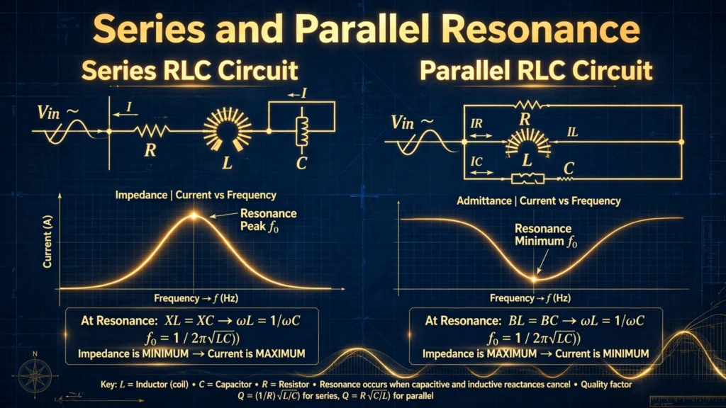
In a series RLC circuit, the total impedance is Z = R + j(XL − XC). At the resonant frequency, XL = XC, so the reactive terms cancel and Z = R — the smallest impedance the circuit can present. With minimum impedance comes maximum current for a given source voltage.
Setting XL = XC and solving for frequency gives the famous resonant frequency formula:
fr = 1 / (2π√(LC))
Key behaviors at series resonance:
- Impedance is minimum and purely resistive (Z = R).
- Circuit current is maximum.
- Voltage across L and across C can each exceed the supply voltage (magnified by the Q factor) — they are equal in magnitude but opposite in phase, so they cancel.
- The circuit looks resistive: voltage and current are in phase (unity power factor).
Parallel Resonance: Maximum Impedance
In a parallel RLC circuit, the inductor and capacitor sit side by side across the same voltage. At resonance, their branch currents are equal and opposite, so they cancel in the main line. The total current drawn from the source drops to a minimum, which means the impedance seen by the source is at its maximum — ideally equal to R (in the practical circuit with coil resistance, approximately so).
The resonant frequency formula is the same:
fr = 1 / (2π√(LC))
Key behaviors at parallel resonance:
- Impedance is maximum (ideally infinite for a lossless circuit).
- Line current is minimum.
- The circulating current between L and C can far exceed the line current (again magnified by Q).
- Used wherever you want to block or select a frequency — the principle behind tuner circuits.
Q Factor: How Sharp Is the Peak?
The quality factor (Q) measures how sharp and selective the resonance is. High Q means a tall, narrow peak (great for radio tuning); low Q means a broad, flat response.
- Series circuit: Q = XL / R = (2πfrL) / R, equivalently Q = (1/R) × √(L/C)
- Parallel circuit: Q = R / XL = R × √(C/L)
Notice the symmetry: in series circuits resistance spoils Q (it sits in the current path), while in parallel circuits resistance boosts it. A Q of 10 is typical for radio coils; crystal oscillators reach tens of thousands.
Bandwidth and the Half-Power Points
The bandwidth (BW) is the range of frequencies around resonance where the circuit delivers at least half its peak power. It connects directly to Q:
BW = fr / Q
The two frequencies at the edges of this band are the half-power (or −3 dB) points. Narrow bandwidth means high selectivity — the circuit responds strongly to its tuned frequency and rejects neighbors. This is exactly what a radio dial exploits, and why measuring frequency accurately matters in tuned systems.
Worked Example 1: Series RLC Circuit
Problem: A series circuit has R = 10 Ω, L = 0.1 H, and C = 100 µF. Find the resonant frequency, Q factor, and bandwidth.
Step 1 — Resonant frequency:
fr = 1 / (2π√(LC)) = 1 / (2π√(0.1 × 100×10⁻⁶))
√(10⁻⁵) = 3.162 × 10⁻³
fr = 1 / (2π × 3.162×10⁻³) = 1 / 0.01987 = 50.3 Hz
Step 2 — Reactance at resonance:
XL = 2πfrL = 2π × 50.3 × 0.1 = 31.6 Ω (XC is identical)
Step 3 — Q factor:
Q = XL / R = 31.6 / 10 = 3.16
Step 4 — Bandwidth:
BW = fr / Q = 50.3 / 3.16 = 15.9 Hz
So this circuit passes frequencies near 50 Hz strongly and attenuates anything far outside a ~16 Hz band.
Worked Example 2: Parallel RLC Circuit
Problem: A parallel circuit has R = 1 kΩ, L = 10 mH, and C = 100 nF. Find fr, Q, and bandwidth.
Step 1 — Resonant frequency:
fr = 1 / (2π√(10×10⁻³ × 100×10⁻⁹)) = 1 / (2π√(10⁻⁹))
√(10⁻⁹) = 3.162 × 10⁻⁵
fr = 1 / (2π × 3.162×10⁻⁵) = 1 / 1.987×10⁻⁴ = 5033 Hz ≈ 5.03 kHz
Step 2 — Q factor (parallel form):
Q = R√(C/L) = 1000 × √(100×10⁻⁹ / 10×10⁻³) = 1000 × √(10⁻⁵)
Q = 1000 × 3.162×10⁻³ = 3.16
Step 3 — Bandwidth:
BW = 5033 / 3.16 = 1593 Hz ≈ 1.59 kHz
At 5.03 kHz this parallel circuit presents maximum impedance and draws minimum line current — the classic tuner behavior.
Where Resonance Is Used
- Radio and TV tuners — select one station’s frequency and reject the rest.
- Filters — band-pass and band-stop filters are resonant circuits at heart.
- Oscillators — crystal and LC oscillators sustain a stable frequency using resonance.
- Wireless charging — transmitter and receiver coils are tuned to the same resonant frequency for efficient energy transfer.
- Power systems — engineers must avoid accidental resonance, which can magnify voltages dangerously.
Frequently Asked Questions
What is resonance in simple words?
Resonance is the condition where inductive and capacitive reactances cancel each other (XL = XC) at a specific frequency. In series circuits this gives minimum impedance and maximum current; in parallel circuits, maximum impedance and minimum line current.
What does the Q factor tell me?
Q measures resonance sharpness. High Q = narrow, tall peak (selective, like a radio tuner). Low Q = broad, flat response. Series Q = XL/R; parallel Q = R/XL.
Why is current maximum at series resonance?
Because impedance is minimum (Z = R, reactances cancel). By Ohm’s law, I = V/Z, so the smallest Z gives the largest current for a fixed source voltage.
Can resonance be dangerous?
Yes. In series resonance, the voltage across the inductor or capacitor can exceed the supply voltage by a factor of Q. In power systems, unintended resonance can damage insulation and equipment — engineers design specifically to avoid it.
What is the difference between series and parallel resonance?
Series resonance: minimum impedance, maximum current, used where you want to pass a frequency. Parallel resonance: maximum impedance, minimum line current, used where you want to select or block a frequency (tuners, filters).
Final Thoughts
Resonance is where AC theory becomes tangible — a single formula, fr = 1/(2π√(LC)), predicts the sweet spot of any LC combination, and the Q factor tells you how sharp that spot is. Work through both examples above with a calculator, and the formulas will stick far better than memorization ever could. For the deeper physics, see electrical resonance on Wikipedia.