
Imagine switching ON a heavy motor. You may notice a spark or a small delay before the motor runs smoothly. This happens because of a property called inductance. It controls how current changes in electrical circuits and plays a key role in protecting equipment.
Inductance is one of the most important concepts in electrical engineering, especially in transformers, motors, and power systems. Without understanding inductance, it becomes difficult to design safe and efficient electrical circuits.
The Inductance Formula helps engineers calculate how much voltage is produced when current changes in a coil. It also explains how energy is stored in a magnetic field.
In this article, you will learn:
- What inductance means in simple terms
- The inductance formula and its detailed explanation
- Working principle with easy examples
- Types of inductors and their uses
- Advantages, disadvantages, and real-world applications
By the end, you will have a strong understanding of inductance and how it is used in practical electrical systems.
2. What is Inductance?
Definition:
Inductance is the property of a conductor or coil that opposes changes in current by producing a voltage.
Simple Explanation:
When current flows through a wire coil, it creates a magnetic field. If the current changes, the magnetic field also changes, producing a voltage that resists the change.
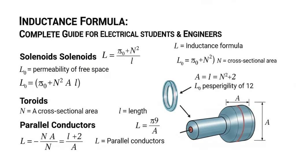
Inductance (Basic Definition Formula)
L=INΦ
Where:
- L = Inductance (Henry, H)
- N = Number of turns in coil
- Φ = Magnetic flux (Weber)
- I = Current (Ampere)
Induced Voltage (Practical Inductance Formula)
V=LdtdI
Where:
- V = Induced voltage (Volts)
- L = Inductance (Henry)
- fracdIdt = Rate of change of current
Energy Stored in Inductor (Important)
W=21LI2
V = L \frac{dI}{dt}
Where:
- V = Induced voltage (Volts)
- L = Inductance (Henry)
- dI/dt = Rate of change of current
Practical Example:
If current in a coil changes quickly:
- A higher voltage is generated
- This can affect circuit performance
This is the core idea of the Inductance Formula.
3. Working Principle of Inductance
The working principle is based on electromagnetic induction.
Step-by-Step Explanation:
- Current flows through a coil
- A magnetic field is created around it
- If current changes, magnetic field changes
- This changing field induces a voltage
- The induced voltage opposes the change in current
Simple Analogy:
Think of a heavy wheel:
- It resists sudden changes in motion
- Similarly, an inductor resists sudden changes in current
Key Points:
- Faster current change → higher induced voltage
- More turns in coil → higher inductance
- Strong magnetic field → more energy stored
This explains the inductance formula working principle.
4. Types / Classification of Inductors
4.1 Air Core Inductor
- No magnetic core
- Low inductance value
- Used in high-frequency circuits
- Air Core Inductor
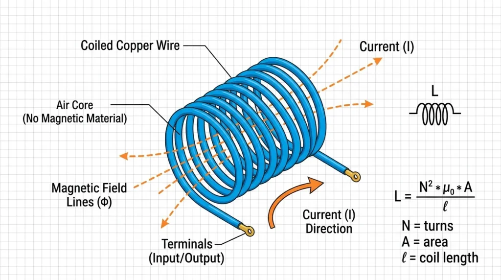
- An Air Core Inductor is a type of inductor that uses air as its core material instead of iron, ferrite, or other magnetic substances. It consists of a conducting wire, usually made of copper, wound into the shape of a coil. Since the space inside the coil contains only air, there is no magnetic core to increase the magnetic field. Air core inductors operate on the principle of electromagnetic induction. When electric current flows through the coil, it produces a magnetic field around it and stores energy in that field. Because air does not become magnetically saturated like iron cores, these inductors maintain excellent linearity and stable performance even at high frequencies. They also eliminate core losses such as hysteresis and eddy current losses, making them highly efficient in radio frequency applications. Air core inductors are widely used in electronic circuits that require high-frequency operation, including radio transmitters, receivers, television equipment, antennas, tuning circuits, oscillators, filters, and communication devices. Their simple construction allows them to provide accurate inductance values with minimal distortion of signals. However, compared to iron core inductors, they generally have lower inductance because air has very low magnetic permeability. To achieve higher inductance values, more turns of wire or larger coil sizes are often required, which can increase the physical dimensions of the component. Another advantage of air core inductors is their ability to function effectively over a wide temperature range without significant changes in performance. They are also lightweight and produce very little energy loss at high frequencies. Despite these benefits, they are not suitable for applications requiring high inductance in compact sizes, such as power supplies and transformers, where magnetic cores are preferred. The inductance of an air core inductor depends on factors such as the number of turns in the coil, the diameter of the coil, the spacing between turns, and the length of the winding. Engineers carefully design these parameters to meet specific circuit requirements. Due to their reliability, efficiency, and superior performance in high-frequency systems, air core inductors remain an important component in modern electronics and communication technology. They play a vital role in ensuring accurate signal processing and stable operation in devices that depend on precise frequency control and minimal power loss.
4.2 Iron Core Inductor
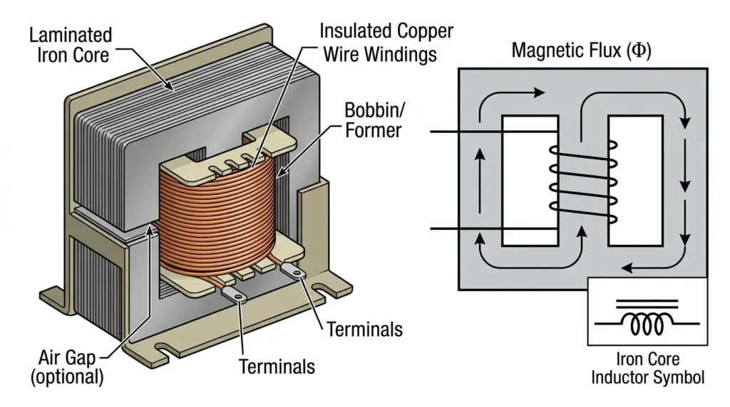
- Uses iron core
- High inductance
- Used in power systems
An Iron Core Inductor is an electrical component that stores energy in the form of a magnetic field and uses an iron core to increase its inductance. It is made by winding insulated copper wire around a core made of soft iron or laminated iron. The presence of the iron core greatly strengthens the magnetic field produced by the coil because iron has high magnetic permeability compared to air. As a result, iron core inductors can achieve high inductance values with fewer turns of wire and a smaller coil size. These inductors operate on the principle of electromagnetic induction. When electric current passes through the winding, it generates a magnetic field around the coil, and the iron core concentrates and amplifies this field. Because of their ability to provide high inductance, iron core inductors are widely used in low-frequency applications such as power supplies, transformers, chokes, filters, relays, and electrical distribution systems. They are especially useful in circuits where smoothing current fluctuations and reducing unwanted noise are important.
One of the major advantages of an iron core inductor is its high efficiency in handling large currents and producing strong magnetic fields. Its compact construction allows designers to obtain greater inductance without increasing the size of the component significantly. Iron core inductors are also cost-effective and durable, making them suitable for industrial and household electrical equipment. However, they have certain limitations. At high frequencies, the iron core can experience energy losses known as hysteresis losses and eddy current losses, which reduce efficiency and generate heat. The core may also become magnetically saturated if the current exceeds a certain limit, causing the inductance to decrease and affecting circuit performance. To minimize eddy current losses, laminated iron cores are often used in their construction.
The inductance of an iron core inductor depends on several factors, including the number of turns in the winding, the type and size of the iron core, the cross-sectional area of the core, and the length of the magnetic path. Engineers carefully select these parameters according to the requirements of the circuit. Despite their limitations at high frequencies, iron core inductors remain essential components in electrical and electronic systems due to their ability to provide high inductance, support heavy loads, and improve the efficiency of power-related applications. They continue to play a vital role in modern technology, particularly in power conversion and energy management systems.
4.3 Ferrite Core Inductor
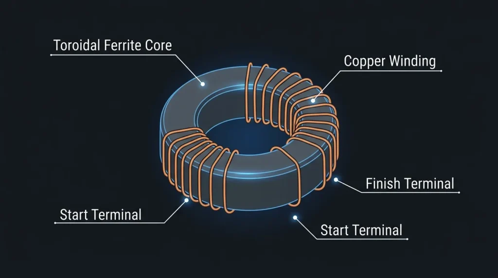
- Made from ferrite material
- Good for high-frequency applications
- Used in electronics
A Ferrite Core Inductor is a type of inductor that uses a ferrite material as its magnetic core to increase inductance and improve performance in high-frequency circuits. Ferrite is a ceramic compound made primarily from iron oxide mixed with other metallic elements such as manganese, zinc, or nickel. This material has high magnetic permeability and very high electrical resistance, making it ideal for reducing energy losses at high frequencies. A ferrite core inductor is constructed by winding insulated copper wire around a ferrite core. When electric current flows through the coil, it generates a magnetic field that is concentrated by the ferrite core, allowing the inductor to store more magnetic energy than an air core inductor of similar size. Because ferrite cores minimize eddy current losses, these inductors are widely used in radio-frequency and switching applications.
Ferrite core inductors are commonly found in switch-mode power supplies, radio transmitters and receivers, television circuits, communication equipment, computer motherboards, filters, oscillators, and noise suppression devices. Their ability to operate efficiently at medium and high frequencies makes them essential in modern electronic systems. One of the major advantages of ferrite core inductors is that they provide high inductance values while maintaining a compact size and lightweight design. They also offer excellent efficiency because the ferrite material significantly reduces heat generation caused by eddy currents. In addition, these inductors help suppress electromagnetic interference (EMI), improving signal quality and system reliability.
Despite their many benefits, ferrite core inductors also have certain limitations. Ferrite materials are brittle and can crack if subjected to mechanical stress or impact. They may also experience magnetic saturation when exposed to excessive current, resulting in a reduction in inductance and circuit efficiency. Furthermore, different ferrite compositions are designed for specific frequency ranges, so selecting the correct ferrite material is important for achieving optimal performance. The inductance of a ferrite core inductor depends on factors such as the number of turns in the coil, the size and shape of the ferrite core, the magnetic permeability of the material, and the operating frequency of the circuit. Engineers carefully consider these factors during the design process.
Due to their compact structure, low core losses, and excellent high-frequency characteristics, ferrite core inductors have become indispensable components in modern electronics. They play a vital role in power conversion, signal filtering, and communication systems, ensuring efficient operation, reduced interference, and improved overall performance of electronic devices.
4.4 Variable Inductor
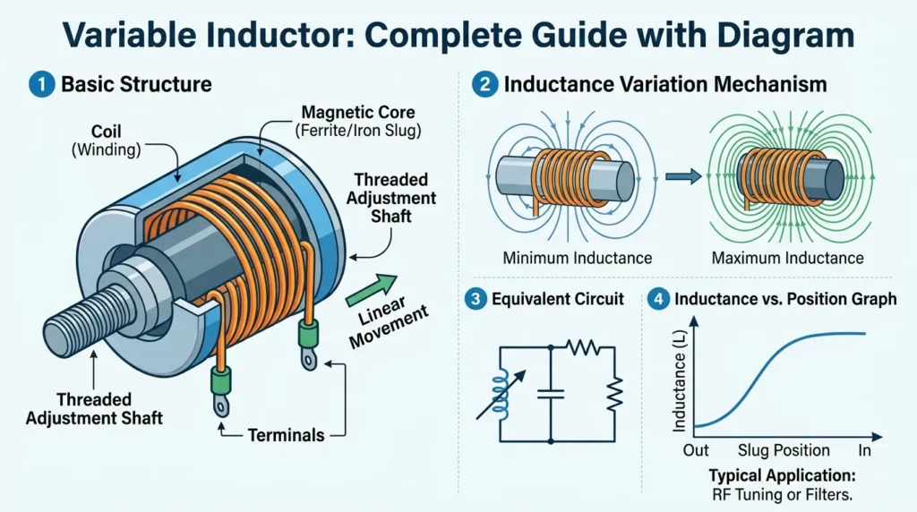
- Inductance can be adjusted
- Used in tuning circuits
A Variable Inductor is an inductor whose inductance value can be adjusted according to the requirements of an electrical or electronic circuit. Unlike fixed inductors, which have a constant inductance, variable inductors allow users to increase or decrease the inductance by changing the position of a movable magnetic core or by adjusting the number of effective turns in the coil. They operate on the principle of electromagnetic induction, where a current flowing through a coil produces a magnetic field that stores energy. By altering the magnetic path within the inductor, the strength of this magnetic field changes, resulting in a different inductance value. Variable inductors are commonly constructed using a coil of insulated copper wire wound around a hollow form, with a threaded ferrite or iron core that can be moved inward or outward using a screw mechanism.
Variable inductors are widely used in applications that require precise tuning and frequency adjustment. They are commonly found in radio transmitters and receivers, television tuning circuits, oscillators, filters, communication equipment, antenna matching networks, and laboratory testing instruments. In these systems, small adjustments to inductance help achieve accurate frequency selection, signal filtering, and optimal circuit performance. One of the main advantages of a variable inductor is its flexibility, as a single component can provide a range of inductance values without replacing the entire device. This feature simplifies circuit design, reduces the need for multiple inductors, and allows technicians to calibrate equipment easily. Variable inductors also improve the accuracy and efficiency of tuned circuits by enabling fine adjustments during operation or maintenance.
However, variable inductors have certain limitations. Their mechanical adjustment mechanisms can wear out over time due to repeated use, affecting reliability and precision. They are generally more expensive than fixed inductors and may not be suitable for applications exposed to vibration or harsh environmental conditions. In addition, their inductance range is limited by their physical design and core material. The inductance of a variable inductor depends on factors such as the number of turns in the coil, the type and position of the movable core, the permeability of the core material, and the dimensions of the winding. Engineers carefully select these parameters to meet specific circuit requirements.
Because of their ability to provide adjustable inductance and precise tuning, variable inductors remain important components in many electronic systems. They play a key role in communication technology, signal processing, and testing equipment, ensuring stable operation and accurate control of frequency-dependent circuits.
Here is the expanded version with proper explanations and more detail for each section.
5. Main Components of an Inductor
An inductor consists of several important components that work together to store energy in the form of a magnetic field. Understanding these parts helps students and technicians learn how inductors function in electrical and electronic circuits.
5.1 Coil (Wire)
The coil is the most important part of an inductor. It is made of a conducting wire, usually insulated copper wire, wound into a series of loops or turns. When electric current passes through the wire, it produces a magnetic field around the coil. The strength of this magnetic field depends on the number of turns in the coil and the amount of current flowing through it. A greater number of turns generally results in higher inductance. The coil acts as the energy-storing element of the inductor and determines many of its electrical characteristics.
5.2 Core Material
The core is the material placed inside the coil to strengthen and guide the magnetic field. It increases the inductance value and improves the efficiency of the inductor. Different applications require different core materials.
Common types of core materials include:
- Air Core: Uses air as the core material and is suitable for high-frequency circuits because it has no core losses.
- Iron Core: Provides high inductance values and is commonly used in low-frequency applications and power systems.
- Ferrite Core: Offers excellent performance at high frequencies due to its low eddy current losses and high magnetic permeability.
The selection of core material depends on operating frequency, required inductance, and application needs.
5.3 Terminals
Terminals are the connecting ends of an inductor that allow it to be attached to an electrical circuit. Through these terminals, current enters and leaves the coil. They provide secure electrical connections on printed circuit boards (PCBs), electronic devices, and industrial equipment. Proper terminal design ensures low resistance and reliable operation of the component.
5.4 Insulation
Insulation is used to cover the conducting wire of the coil and separate adjacent turns. It prevents short circuits between the turns of the winding and protects the inductor from electrical failures. Good insulation improves safety, increases durability, and allows the inductor to operate efficiently under various voltage conditions.
6. Advantages of Inductance
Inductance provides several benefits that make inductors essential components in modern electrical and electronic systems.
Smooth Control of Current Changes
An inductor opposes sudden changes in current flow. This property helps maintain a steady current and prevents abrupt fluctuations that could damage sensitive components.
Energy Storage Capability
Inductors store electrical energy in the form of a magnetic field when current flows through them. This stored energy can be released back into the circuit when needed, improving overall circuit performance.
Protection Against Voltage Surges
Inductors help protect circuits from sudden current surges and electrical disturbances. They reduce the impact of transient conditions and contribute to equipment safety.
Effective Filtering
Inductors are widely used in filter circuits to block unwanted high-frequency signals while allowing desired frequencies to pass. This improves signal quality and reduces electrical noise.
Improved System Stability
By smoothing current and minimizing disturbances, inductors enhance the stability and reliability of power supplies and electronic devices.
These characteristics highlight the practical importance of inductance in various applications.
7. Disadvantages and Limitations of Inductance
Although inductors offer many advantages, they also have certain limitations that engineers must consider during circuit design.
Energy Losses
The wire used in an inductor has some resistance. This resistance causes power losses in the form of heat, reducing overall efficiency.
Heat Generation
During operation, especially at high currents, inductors may generate heat. Excessive heating can affect performance and shorten the lifespan of the component.
Large Size for High Inductance
Obtaining high inductance values often requires more turns of wire or larger cores. This increases the physical size and weight of the inductor.
Limited High-Frequency Performance
Some inductors, particularly iron core inductors, experience hysteresis and eddy current losses at high frequencies. These losses reduce efficiency and limit their use in certain applications.
Magnetic Interference
The magnetic field produced by inductors can interfere with nearby electronic components. Proper shielding and circuit layout are often necessary to minimize electromagnetic interference.
Despite these limitations, inductors remain indispensable in countless electrical and electronic systems.
8. Applications of Inductance
The principles of inductance are applied in a wide variety of fields, ranging from household appliances to advanced technological systems.
8.1 Home Applications
Inductors are commonly found in everyday household devices.
Fans and Electric Motors
Inductors help control current flow and generate magnetic fields required for motor operation in ceiling fans, exhaust fans, and other appliances.
Power Adapters and Chargers
Phone chargers and laptop adapters use inductors to regulate voltage and filter unwanted electrical noise.
Televisions and Radios
Inductors play an important role in tuning circuits, signal processing, and power regulation within entertainment devices.
8.2 Industrial Applications
Industries depend heavily on inductance for efficient operation of electrical systems.
Transformers
Transformers use inductive principles to transfer electrical energy between circuits and change voltage levels for transmission and distribution.
Motor Drives
Industrial motor control systems use inductors to improve efficiency, regulate current, and protect motors from sudden fluctuations.
Power Systems
Inductors are employed in substations and transmission networks to limit fault currents and stabilize power delivery.
8.3 Electronics Applications
Electronic circuits rely extensively on inductors.
Filters
Inductors are used in low-pass, high-pass, band-pass, and band-stop filters to control signal frequencies and reduce noise.
Signal Processing
Communication devices use inductors to improve signal clarity and remove unwanted interference.
Oscillators
Oscillator circuits use inductors with capacitors to generate stable frequencies in radios, televisions, and wireless communication systems.
8.4 Modern Technology Applications
Advances in technology have expanded the use of inductance into innovative fields.
Electric Vehicles (EVs)
Inductors are essential components in electric vehicle power converters, charging systems, and motor control units, helping improve energy efficiency.
Renewable Energy Systems
Solar inverters and wind energy converters use inductors to regulate power flow and ensure stable energy conversion.
Wireless Charging
Wireless charging systems for smartphones, smartwatches, and electric vehicles operate through inductive coupling, allowing energy transfer without direct electrical contact.
The widespread use of inductance demonstrates its importance in both traditional electrical engineering and emerging technologies.
9. Comparison Section
Inductor vs Capacitor
| Feature | Inductor | Capacitor |
|---|---|---|
| Energy Storage | Magnetic field | Electric field |
| Opposes | Change in current | Change in voltage |
| Unit | Henry | Farad |
| Usage | Filters, motors | Timing, storage |
Key Difference:
- Inductor resists current change
- Capacitor resists voltage change
This is the difference between inductor and capacitor.
10. Selection Guide
When choosing an inductor:
- Check inductance value (Henry)
- Choose correct core material
- Consider current rating
- Check size and design
- Match frequency requirements
Beginner Tip:
Start with standard inductors and gradually learn advanced selection.
11. Common Problems & Solutions
Problem 1: Inductor overheating
- Cause: Excess current
- Solution: Use higher-rated inductor
Problem 2: Noise in circuit
- Cause: Magnetic interference
- Solution: Use shielding
Problem 3: Low performance
- Cause: Wrong inductance value
- Solution: Replace with correct value
Problem 4: Coil damage
- Cause: Overheating or aging
- Solution: Replace inductor
12. Future Trends in Inductance
New Technologies:
- High-efficiency compact inductors
- Nano-core materials
- Smart inductive components
- Wireless power transfer systems
Industry Direction:
- Smaller and more efficient devices
- Integration in microelectronics
- Improved energy storage systems
13. Conclusion
The Inductance Formula is a fundamental concept in electrical engineering. It explains how voltage is generated when current changes in a circuit. This property is essential for designing safe and efficient electrical systems.
We explored the formula, working principle, types of inductors, components, applications, and troubleshooting methods. We also discussed advantages, limitations, and future developments in inductive technology.
For students and engineers, understanding inductance is critical for working with motors, transformers, and electronic circuits. It builds a strong foundation for advanced topics in power systems and electronics.
In simple terms, inductance is not just a theory—it is a powerful principle that controls energy flow in modern electrical systems.