Imagine a factory running large motors, transformers, and air conditioning systems using alternating current (AC) power. Even though voltage is available, the current does not flow freely because the circuit opposes it. This opposition is not caused only by resistance. In AC circuits, inductors and capacitors also affect current flow. The total opposition offered to AC current is called impedance.
The Impedance Formula is one of the most important concepts in electrical engineering because it helps engineers calculate current, voltage drop, power consumption, and circuit performance in AC systems. Without understanding impedance, designing electrical systems such as transformers, motors, generators, and communication circuits becomes difficult.
Impedance combines resistance and reactance into a single value. It explains how AC circuits behave under different frequencies and load conditions. This concept is essential for students, electricians, technicians, and engineers working with modern electrical and electronic systems.
In this article, you will learn the impedance formula, impedance working principle, types of impedance, components, applications, advantages and disadvantages, troubleshooting methods, comparison with resistance, and future developments in electrical technology.
What is Impedance Formula?
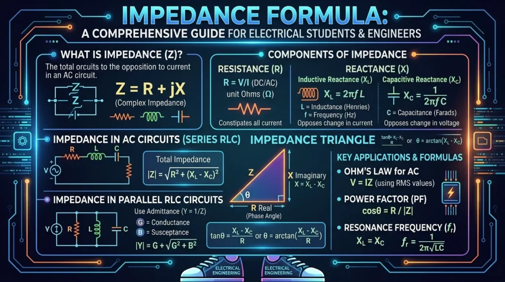
The Impedance Formula is used to calculate the total opposition to alternating current in an AC circuit.
Definition of Impedance
Impedance is the combined effect of:
- Resistance (R)
- Inductive Reactance (XL)
- Capacitive Reactance (XC)
It is represented by the symbol Z and measured in Ohms (Ω).
The basic impedance formula is:
Z=\sqrt{R^2+(X_L-X_C)^2}
Where:
- (Z) = Impedance
- (R) = Resistance
- (X_L) = Inductive Reactance
- (X_C) = Capacitive Reactance
Simple Explanation
In a DC circuit, only resistance opposes current flow. But in AC circuits, coils and capacitors also affect the movement of current. Impedance represents the total opposition created by all these components together.
Practical Example
Suppose an AC circuit contains:
- Resistance = 6Ω
- Inductive reactance = 8Ω
- Capacitive reactance = 2Ω
Using the formula:
[
Z = \sqrt{6^2 + (8-2)^2}
]
[
Z = \sqrt{36 + 36}
]
[
Z = \sqrt{72}
]
[
Z \approx 8.48\Omega
]
So the total impedance is approximately 8.48Ω.
Impedance Working Principle
The impedance working principle explains how AC current faces opposition inside electrical circuits.
Step-by-Step Working
Step 1: AC Voltage is Applied
Alternating voltage is supplied to the circuit.
Step 2: Current Begins to Flow
Electrons move through the conductor.
Step 3: Resistance Opposes Current
The resistor converts electrical energy into heat.
Step 4: Inductors Create Magnetic Opposition
Inductors oppose changes in current using magnetic fields.
Step 5: Capacitors Oppose Voltage Changes
Capacitors store electrical energy temporarily.
Step 6: Combined Opposition Forms Impedance
All these effects combine to create total impedance.
Easy Analogy
Imagine water flowing through a pipe:
- Narrow pipe section = Resistance
- Rotating wheel slowing water = Inductive reactance
- Flexible membrane storing pressure = Capacitive reactance
Together they reduce water flow, similar to impedance reducing AC current.
Types / Classification of Impedance
Resistive Impedance
Occurs when only resistance is present.
Features
- Voltage and current stay in phase
- No reactance effect
- Common in heaters and incandescent lamps
Formula:
Z=R
Inductive Impedance
Occurs when inductors are present in the circuit.
Features
- Current lags voltage
- Found in motors and transformers
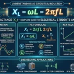
Inductive reactance formula:
X_L=2\pi fL
Where:
- (f) = Frequency
- (L) = Inductance
Capacitive Impedance
Occurs when capacitors are present.
Features
- Current leads voltage
- Used in filters and electronic circuits
Capacitive reactance formula:
X_C=\frac{1}{2\pi fC}
Where:
- (C) = Capacitance
Series Impedance
Components are connected one after another.
Characteristics
- Same current flows through all components
- Impedance adds together
Parallel Impedance
Components are connected across the same voltage source.
Characteristics
- Current divides into branches
- More complex calculations
Main Components of Impedance
Resistance (R)
Resistance opposes current and converts electrical energy into heat.
Examples
- Electric heaters
- Bulbs
- Resistors
Inductive Reactance (XL)
Created by inductors and coils.
Function
Opposes changes in current flow.
Capacitive Reactance (XC)
Created by capacitors.
Function
Opposes changes in voltage.
Frequency (f)
Frequency strongly affects reactance values.
Important Point
Higher frequency increases inductive reactance but decreases capacitive reactance.
Advantages of Impedance Formula
The impedance advantages and disadvantages are important for AC circuit design.
Advantages
- Helps calculate AC circuit current
- Essential for power system design
- Useful in transformer calculations
- Supports motor performance analysis
- Helps design communication circuits
- Improves power factor correction
- Assists in electrical troubleshooting
Disadvantages / Limitations
Limitations of Impedance
- Complex calculations in large systems
- Depends on frequency changes
- Difficult for beginners to understand
- Requires reactance knowledge
- Phase angle calculations may become complicated
Impedance Applications
The impedance applications are extremely important in electrical and electronic engineering.
Home Applications
- Air conditioners
- Fans
- Refrigerators
- Washing machines
Industrial Applications
- Electric motors
- Transformers
- Industrial machinery
- Welding equipment
Communication Systems
- Radio transmitters
- Antenna systems
- Audio circuits
Power Systems
- Transmission lines
- Substations
- Power distribution networks
Modern Electronics
- Filters
- Amplifiers
- Inverters
- Computer power supplies
Comparison Section
Difference Between Impedance and Resistance
| Feature | Impedance | Resistance |
|---|---|---|
| Works In | AC circuits | AC and DC circuits |
| Includes Reactance | Yes | No |
| Symbol | Z | R |
| Depends on Frequency | Yes | No |
| Unit | Ohm | Ohm |
Difference Between Inductive and Capacitive Reactance
| Feature | Inductive Reactance | Capacitive Reactance |
|---|---|---|
| Symbol | XL | XC |
| Caused By | Inductors | Capacitors |
| Frequency Effect | Increases with frequency | Decreases with frequency |
| Current Behavior | Current lags | Current leads |
Selection Guide
How to Choose Proper Impedance
For Beginners
- Identify AC supply frequency
- Measure resistance accurately
- Determine inductive or capacitive loads
Engineering Tips
Match Equipment Impedance
Improper impedance matching reduces efficiency.
Consider Power Factor
Low power factor increases current flow.
Avoid Overloading
High impedance mismatch may damage equipment.
Common Problems & Solutions
Problem 1: Excessive Current
Cause
Low impedance in circuit.
Solution
Increase resistance or reduce load.
Problem 2: Voltage Drop
Cause
High impedance in transmission lines.
Solution
Use larger conductors.
Problem 3: Motor Heating
Cause
Improper impedance matching.
Solution
Correct power factor and load conditions.
Problem 4: Signal Loss in Audio Systems
Cause
Impedance mismatch.
Solution
Use matching impedance devices.
Problem 5: Poor Power Factor
Cause
Excessive inductive reactance.
Solution
Install capacitor banks.
Future Trends
Smart Power Systems
Modern smart grids continuously monitor impedance for system protection.
Advanced Power Electronics
New semiconductor devices improve impedance control in electronic circuits.
Wireless Power Transfer
Future wireless charging systems depend heavily on impedance matching.
Renewable Energy Systems
Solar and wind systems use impedance calculations for inverter efficiency.
AI-Based Electrical Monitoring
Artificial intelligence is helping industries analyze impedance automatically for predictive maintenance.
Conclusion
The Impedance Formula is one of the most important concepts in AC electrical engineering. It explains the total opposition offered to alternating current by resistance, inductance, and capacitance. Understanding impedance helps engineers design safe, efficient, and reliable electrical systems.
From household appliances to industrial motors and communication systems, impedance calculations are used everywhere in modern technology. Learning impedance working principle, reactance behavior, and impedance applications helps students and professionals solve real electrical problems effectively.
As electrical systems become more advanced with renewable energy, automation, and smart technologies, impedance knowledge will remain essential for every electrical engineer and technician.