
Imagine turning on an electric heater at home. The heater becomes hot because electrical resistance controls the flow of current and converts electrical energy into heat. Without resistance, electrical devices could draw too much current and become damaged within seconds. This is why understanding the resistance formula is extremely important for electrical students, engineers, technicians, and beginners.
The resistance formula is one of the most basic and essential concepts in electrical engineering. It helps calculate how much a material or component opposes the flow of electric current. Whether you are designing circuits, repairing appliances, or studying electrical systems, resistance plays a major role in safe and efficient operation.
In this article, you will learn the resistance formula definition, resistance working principle, types of resistance, applications, advantages and disadvantages, comparison with related electrical concepts, troubleshooting methods, and future trends. The explanations are written in simple and easy English so beginners can understand the topic clearly.
2. What Is the Resistance Formula? (2026): Definition, Equation, Explanation, and Real-World Examples
The resistance formula is a mathematical equation used to calculate the electrical resistance of a conductor or an electrical circuit. Resistance is the property of a material that opposes or restricts the flow of electric current. It is measured in ohms (Ω) and plays a vital role in controlling current, protecting electrical components, and ensuring the safe operation of electrical and electronic systems.
Engineers, electricians, technicians, and students use the resistance formula every day to design circuits, troubleshoot electrical faults, calculate current flow, and select the correct resistors for different applications.
The most commonly used resistance formula is derived from Ohm’s Law, which describes the relationship between voltage, current, and resistance.
Standard Resistance Formula (Ohm’s Law)
[
R=\frac{V}{I}
]
Where:
- R = Resistance (Ohms, Ω)
- V = Voltage (Volts, V)
- I = Current (Amperes, A)
This equation shows that resistance is equal to the applied voltage divided by the electric current flowing through the circuit.
If the voltage increases while the current remains constant, the resistance becomes higher. Likewise, if the current increases for the same voltage, the resistance decreases.
2.1 Simple Explanation of the Resistance Formula
Understanding resistance becomes much easier when comparing electricity to water flowing through a pipe.
Imagine that electrical current is like water moving through a pipe:
- Voltage acts like the water pressure.
- Current represents the amount of water flowing.
- Resistance is similar to a blockage or narrowing inside the pipe.
A pipe with very little blockage allows water to flow easily. However, if the pipe becomes narrow or partially blocked, less water can pass through.
The same principle applies to electricity:
- Low resistance allows more current to flow.
- High resistance restricts current flow.
This simple analogy helps explain why resistance is essential for controlling electricity safely in every electrical circuit.
2.2 Practical Example of the Resistance Formula
The resistance formula is widely used in practical electrical calculations.
Example 1
Suppose an electric bulb operates with:
- Voltage = 12 V
- Current = 2 A
Using Ohm’s Law:
[
R=\frac{V}{I}
]
[
R=\frac{12}{2}=6\ \Omega
]
Answer: The bulb has a resistance of 6 Ω (ohms).
Example 2
A resistor is connected to a 24 V power supply and allows 4 A of current to flow.
[
R=\frac{24}{4}=6\ \Omega
]
Again, the resistance is 6 Ω.
These simple calculations help engineers verify whether a circuit is operating correctly.
3. Resistance Working Principle (2026): How Electrical Resistance Works
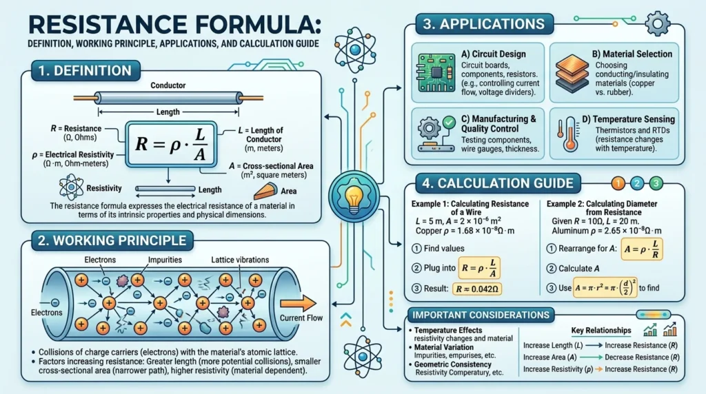
The working principle of resistance is based on the interaction between moving electrons and the atoms inside a conducting material. When electric current flows through a conductor, electrons continuously collide with atoms in the material. These collisions oppose the movement of electrons, creating resistance.
The greater the opposition, the more difficult it becomes for electric current to flow.
During this process, part of the electrical energy is converted into heat energy, which is why resistors and electrical wires become warm during operation.
3.1 Step-by-Step Working Principle of Resistance
The resistance process can be understood through the following steps:
Step 1: Voltage Is Applied
A voltage source such as a battery or power supply creates an electric field that pushes electrons through the conductor.
Step 2: Electrons Begin Moving
Free electrons start flowing through the conductive material, creating electric current.
Step 3: Electron Collisions Occur
As electrons move, they collide with atoms and impurities inside the conductor. These collisions slow the movement of electrons.
Step 4: Resistance Opposes Current Flow
The continuous collisions create resistance, limiting the amount of current that can flow through the circuit.
Step 5: Heat Is Generated
Some electrical energy is converted into heat because of the friction-like effect caused by electron collisions. This phenomenon is known as Joule heating.
Step 6: Stable Circuit Operation
The electrical circuit operates according to the resistance value, ensuring that current remains within safe operating limits and protecting electrical components from excessive current.
3.2 Easy Analogy to Understand Resistance
Imagine people walking through a hallway.
- A wide, empty hallway allows people to walk quickly and easily.
- A crowded, narrow hallway slows everyone down because movement becomes difficult.
Electricity behaves in a similar way.
- Low resistance acts like a wide hallway, allowing more current to flow.
- High resistance acts like a crowded hallway, restricting the movement of electrons.
This simple comparison makes it easier to understand why resistance controls current flow in electrical circuits.
3.3 Factors Affecting Resistance
The amount of resistance in a conductor depends on several physical properties.
Length of the Conductor
A longer conductor offers greater resistance because electrons must travel a longer distance and experience more collisions.
Cross-Sectional Area (Thickness)
A thicker conductor provides a larger path for electrons to flow, reducing resistance. Conversely, a thinner conductor has higher resistance.
Material Type
Different materials have different electrical resistivities.
- Copper and silver have low resistance.
- Aluminum has moderate resistance.
- Nichrome has relatively high resistance and is commonly used in heating elements.
Temperature
For most metallic conductors, resistance increases as temperature rises because atoms vibrate more intensely, causing additional electron collisions.
3.4 Resistance Formula for Conductors
The resistance of a conductor can also be calculated using its physical dimensions and material properties.
[
R=\rho\frac{L}{A}
]
Where:
- R = Resistance (Ohms, Ω)
- ρ (rho) = Resistivity of the material (Ω·m)
- L = Length of the conductor (meters)
- A = Cross-sectional area of the conductor (square meters)
What This Formula Means
- Increasing the length (L) increases resistance.
- Increasing the cross-sectional area (A) decreases resistance.
- Materials with higher resistivity (ρ) offer greater resistance to current flow.
This formula is extensively used in electrical engineering for selecting wire sizes, designing transmission lines, calculating cable resistance, and optimizing electrical system performance.
3.5 Why Understanding the Resistance Formula Matters
The resistance formula is one of the most fundamental equations in electrical engineering. It forms the basis for circuit analysis, electrical design, power calculations, troubleshooting, and equipment protection.
Whether designing household wiring, industrial control panels, electronic devices, renewable energy systems, or communication networks, understanding how resistance works enables engineers, electricians, technicians, and students to build safer, more efficient, and more reliable electrical systems in 2026 and beyond.
Types of Resistance (2026): Complete Guide to Different Types of Electrical Resistance
Electrical resistance can be classified into several types based on how its value behaves under different operating conditions. Some types maintain a constant resistance, while others change with temperature, light, voltage, or manual adjustment. Understanding these different types helps engineers, electricians, technicians, and students select the most suitable resistance component for specific electrical and electronic applications.
Each type of resistance has unique characteristics, advantages, and practical uses in modern electrical systems.
Fixed Resistance
Fixed resistance remains constant throughout normal operation. Its resistance value cannot be adjusted after manufacturing, making it the most commonly used type of resistance in electrical and electronic circuits.
Fixed resistors provide stable and reliable performance, making them ideal for circuits where a constant current or voltage is required.
Common Types of Fixed Resistors
- Carbon Composition Resistors
- Carbon Film Resistors
- Metal Film Resistors
- Metal Oxide Resistors
- Wire-Wound Resistors
- Thick Film Resistors
- Thin Film Resistors
Advantages
- Stable resistance value
- High reliability
- Low cost
- Easy to install
- Available in a wide range of resistance values
Applications
- Printed Circuit Boards (PCBs)
- LED circuits
- Consumer electronics
- Power supplies
- Household appliances
- Industrial control systems
- Communication equipment
Variable Resistance
Variable resistance allows the resistance value to be adjusted manually or electronically according to circuit requirements. It is widely used in applications where current, voltage, or signal levels need to be controlled.
Variable resistors provide flexibility during circuit calibration and equipment operation.
Common Types of Variable Resistors
- Potentiometers
- Rheostats
- Trimmer Potentiometers
- Digital Potentiometers
Advantages
- Adjustable resistance
- Easy circuit tuning
- Flexible current control
- Improves calibration accuracy
- Suitable for testing and experimentation
Applications
- Audio volume controls
- Light dimmer switches
- Motor speed controllers
- Laboratory equipment
- Electronic testing instruments
- Adjustable power supplies
Thermal Resistance (Temperature-Dependent Resistance)
Thermal resistance refers to resistance that changes as temperature changes. Components that operate on this principle are called thermistors, and they are highly sensitive to temperature variations.
Thermistors are generally classified into:
- NTC (Negative Temperature Coefficient): Resistance decreases as temperature increases.
- PTC (Positive Temperature Coefficient): Resistance increases as temperature increases.
Advantages
- Highly sensitive to temperature
- Fast response time
- Compact design
- Reliable temperature measurement
- Excellent circuit protection
Applications
- Temperature sensors
- Battery protection systems
- Air conditioners
- Refrigerators
- Medical equipment
- Industrial automation
- HVAC control systems
- Overcurrent protection circuits
Light-Dependent Resistance (LDR)
A Light-Dependent Resistor (LDR), also called a photoresistor, changes its resistance according to the intensity of light falling on its surface.
When light intensity increases, the resistance decreases. In darkness, the resistance becomes much higher.
Advantages
- Automatic light detection
- Simple operation
- Low power consumption
- Cost-effective
- High sensitivity to light
Applications
- Automatic street lighting
- Solar garden lights
- Camera exposure systems
- Light sensors
- Security systems
- Smart home automation
- Industrial lighting control
Superconductive Resistance
Certain materials exhibit almost zero electrical resistance when cooled below a critical temperature. This remarkable phenomenon is known as superconductivity.
Because electrical current can flow with almost no energy loss, superconducting materials are considered one of the most promising technologies for future electrical systems.
Advantages
- Near-zero electrical resistance
- Extremely high efficiency
- Minimal power loss
- Powerful magnetic field generation
- High current-carrying capability
Applications
- MRI (Magnetic Resonance Imaging) machines
- Particle accelerators
- Magnetic levitation (Maglev) trains
- Scientific research laboratories
- Superconducting power cables
- Fusion energy research
- Advanced electrical grids
Voltage-Dependent Resistance (Varistors)
Voltage-dependent resistance changes according to the applied voltage. The most common example is the Metal Oxide Varistor (MOV), which protects electrical equipment from voltage surges and transient overvoltages.
Advantages
- Excellent surge protection
- Fast response to voltage spikes
- Protects sensitive electronics
- Improves system reliability
Applications
- Surge protectors
- Power supplies
- UPS systems
- Household appliances
- Industrial electrical panels
- Communication equipment
Why Understanding Resistance Types Is Important
Each type of resistance is designed for a specific purpose. Selecting the correct type improves circuit performance, increases equipment reliability, enhances electrical safety, and reduces maintenance costs.
Whether designing consumer electronics, industrial automation systems, renewable energy installations, or advanced medical equipment, understanding the different types of resistance remains a fundamental skill for engineers, electricians, technicians, and students in 2026.
Main Components Related to Resistance (2026): Essential Parts of a Resistor and Their Functions
Resistance in an electrical circuit is primarily produced by a resistor, one of the most important passive electrical components. Although resistors may appear simple from the outside, they are carefully designed using several internal and external parts that work together to control current flow, regulate voltage, and protect electrical equipment.
Each component of a resistor contributes to its performance, durability, accuracy, and reliability. Understanding these parts helps students, electricians, technicians, and engineers choose the right resistor for different electrical and electronic applications.
Below are the main components related to resistance and their functions.
Resistor Element (Resistance Material)
The resistor element is the most important part of a resistor because it provides the actual electrical resistance. It is manufactured using specially selected materials that restrict the flow of electric current while converting a small amount of electrical energy into heat.
The resistance value of the resistor depends on the material, length, thickness, and cross-sectional area of the resistor element.
Functions of the Resistor Element
- Limits the flow of electric current.
- Controls voltage distribution within a circuit.
- Dissipates excess electrical energy as heat.
- Protects sensitive electronic components.
- Maintains stable circuit performance.
- Helps regulate power consumption.
Common Applications
- Electronic circuits
- Power supplies
- LED current limiting
- Motor control circuits
- Voltage divider networks
- Industrial automation systems
Conductive and Resistive Materials
The material used inside a resistor greatly affects its electrical characteristics, temperature stability, precision, and power-handling capability. Different materials are selected depending on the application and required performance.
Common Resistance Materials
- Carbon
- Graphite
- Copper-Nickel Alloy
- Nichrome
- Manganin
- Constantan
- Metal Film
- Carbon Film
- Metal Oxide
- Wire-Wound Alloys
Each material offers different advantages in terms of resistance stability, heat tolerance, accuracy, and durability.
Importance of Material Selection
- Determines resistance value.
- Improves temperature stability.
- Reduces electrical noise.
- Increases operating life.
- Enhances measurement accuracy.
- Supports high-power applications.
Insulating Body (Protective Housing)
The insulating body surrounds the resistor element and provides both mechanical protection and electrical insulation. It prevents accidental contact with conductive parts while protecting the resistor from environmental damage.
Depending on the resistor type, the insulating body may be made of ceramic, epoxy resin, glass, or high-quality plastic materials.
Functions of the Insulating Body
- Prevents electrical shock.
- Protects the resistor from physical damage.
- Provides electrical insulation.
- Improves heat resistance.
- Supports long-term durability.
- Helps maintain stable resistor performance.
Benefits
- Improved user safety.
- Better environmental protection.
- Longer component lifespan.
- Reduced maintenance requirements.
Connecting Leads (Terminals)
Connecting leads are the metal wires attached to both ends of a resistor. These leads connect the resistor to the electrical circuit, allowing current to enter and leave the resistor safely.
Modern surface-mount resistors (SMD resistors) use metal terminals instead of traditional wire leads.
Functions of Connecting Leads
- Connect the resistor to the electrical circuit.
- Provide a reliable electrical path.
- Ensure secure soldering on circuit boards.
- Improve mechanical stability.
- Minimize connection resistance.
Types of Connections
- Axial leads
- Radial leads
- Surface Mount Device (SMD) terminals
- Industrial screw terminals (high-power resistors)
Protective Coating (Outer Layer)
The protective coating forms the outer covering of the resistor and shields it from environmental conditions such as moisture, dust, chemicals, and excessive heat. This coating also helps preserve the resistor’s electrical characteristics throughout its service life.
Common coating materials include epoxy resin, silicone coatings, ceramic coatings, and specialized insulating compounds.
Functions of the Protective Coating
- Prevents moisture penetration.
- Protects against corrosion.
- Reduces dust contamination.
- Increases heat resistance.
- Improves mechanical strength.
- Extends component lifespan.
Advantages
- Better reliability in harsh environments.
- Increased resistance to vibration.
- Improved long-term stability.
- Reduced maintenance costs.
Resistance Value Marking
Every resistor must display its resistance value so that technicians can identify and install the correct component. Depending on the resistor type, this information may be shown using color bands, printed numbers, or alphanumeric codes.
Common Identification Methods
- Resistor color code bands
- Numerical resistance markings
- Surface-mount resistor codes
- Manufacturer identification labels
Importance
- Prevents incorrect resistor selection.
- Simplifies circuit assembly.
- Improves maintenance efficiency.
- Reduces installation errors.
Heat Dissipation Structure
As current flows through a resistor, electrical energy is converted into heat. Therefore, every resistor is designed to safely dissipate this heat without exceeding its maximum operating temperature.
High-power resistors often include ceramic bodies, aluminum housings, or external heat sinks to improve cooling performance.
Functions
- Dissipates generated heat.
- Prevents overheating.
- Protects nearby components.
- Improves power-handling capability.
- Increases operational reliability.
Why These Components Are Important
Every component of a resistor plays a critical role in ensuring accurate resistance, safe operation, and long-term reliability. From the resistor element that controls current to the protective coating that guards against environmental damage, each part contributes to the overall performance of electrical and electronic systems.
Understanding these components helps engineers, electricians, technicians, and students select the right resistor, troubleshoot electrical problems effectively, and design circuits that are safe, efficient, and dependable. As electrical technology continues to advance in 2026, knowledge of resistor construction and resistance-related components remains an essential part of electrical engineering and electronics.
Advantages of the Resistance Formula (2026): Benefits for Circuit Design, Safety, and Electrical Engineering
The resistance formula is one of the most useful mathematical tools in electrical engineering. It enables engineers, electricians, technicians, and students to calculate the correct resistance required for a circuit, ensuring safe and efficient electrical operation. From designing electronic devices to troubleshooting industrial equipment, the resistance formula is applied in countless real-world situations.
Understanding and using this formula correctly helps improve circuit performance, reduce power losses, and protect electrical components from damage.
Accurate Circuit Design and Analysis
One of the biggest advantages of the resistance formula is its ability to support accurate circuit design. Engineers use it to calculate the proper resistance values needed for different electrical and electronic applications.
Accurate calculations help ensure that each component operates within its specified limits, improving the overall performance and reliability of the circuit.
Benefits
- Calculates the correct resistance value for circuits.
- Improves electrical system performance.
- Prevents overload and overcurrent conditions.
- Supports efficient voltage and current distribution.
- Reduces design errors during circuit development.
Easy and Safe Current Control
The resistance formula allows engineers to control the flow of electrical current according to circuit requirements. By selecting the correct resistor value, excessive current can be limited before it damages sensitive electrical components.
Benefits
- Controls electrical current safely.
- Protects electronic components from overcurrent.
- Improves circuit stability.
- Increases equipment lifespan.
- Enhances overall electrical reliability.
Simplifies Electrical Troubleshooting
Electrical technicians frequently use the resistance formula while diagnosing circuit faults. Comparing calculated resistance values with measured values helps identify damaged resistors, loose connections, or wiring faults.
Benefits
- Identifies faulty electrical components.
- Simplifies fault diagnosis.
- Speeds up maintenance and repairs.
- Supports preventive maintenance.
- Reduces equipment downtime.
Improves Electrical Safety
Proper resistance calculations play an important role in electrical safety. They help prevent excessive current flow, overheating, insulation damage, and electrical fires.
Benefits
- Prevents resistor overheating.
- Reduces short-circuit risks.
- Protects electrical equipment.
- Improves workplace safety.
- Supports compliance with electrical safety standards.
Supports Energy Efficiency
The resistance formula helps engineers optimize electrical circuits to minimize unnecessary power losses. Efficient resistance selection reduces wasted electrical energy and improves overall system performance.
Benefits
- Reduces power loss.
- Improves energy efficiency.
- Lowers operating costs.
- Enhances system performance.
- Supports sustainable electrical design.
Essential for Learning Electrical Engineering
For students and beginners, the resistance formula is one of the first concepts learned in electrical engineering. It provides the foundation for understanding more advanced topics such as Ohm’s Law, circuit analysis, power calculations, and electronic design.
Benefits
- Easy to understand.
- Strengthens problem-solving skills.
- Builds a solid engineering foundation.
- Widely used in laboratories and practical training.
- Prepares students for advanced electrical concepts.
Resistance Formula Advantages and Disadvantages (2026): Complete Comparison
Like every engineering concept, the resistance formula offers numerous benefits while also having certain limitations. Understanding both helps engineers and technicians design more efficient and reliable electrical systems.
Advantages of the Resistance Formula
The resistance formula remains an essential tool because it simplifies electrical calculations and improves circuit design across residential, commercial, industrial, and electronic applications.
Major Advantages
- Simple and easy mathematical calculation.
- Easy to apply in electrical and electronic circuits.
- Helps determine the correct resistance value.
- Improves electrical safety by limiting excessive current.
- Supports accurate circuit design and analysis.
- Simplifies electrical testing and troubleshooting.
- Reduces the risk of equipment damage.
- Improves energy management and system efficiency.
- Essential for power systems and electronic devices.
- Used extensively in education, research, and industry.
Disadvantages of the Resistance Formula
Although the resistance formula is highly useful, practical electrical systems may experience limitations because resistance is influenced by several real-world factors such as temperature, material properties, and aging.
Major Disadvantages
- High resistance can generate excessive heat.
- Increased resistance leads to higher power losses.
- Resistance values may change with temperature.
- Corrosion and aging can affect resistance accuracy.
- Incorrect resistance selection may damage electrical equipment.
- Very high resistance reduces current flow and system efficiency.
- Additional calculations may be required for complex AC circuits involving inductance and capacitance.
Advantages vs. Disadvantages at a Glance
| Advantages | Disadvantages |
|---|---|
| Simple and easy to calculate | High resistance produces heat |
| Improves circuit design accuracy | Power loss increases with resistance |
| Enhances electrical safety | Resistance changes with temperature |
| Supports fault diagnosis | Incorrect values can damage equipment |
| Controls current effectively | Material aging affects resistance |
| Improves energy efficiency | Not sufficient alone for complex AC circuit analysis |
| Essential for education and engineering | Requires accurate measurements for reliable results |
Why Understanding Both Is Important
Knowing both the advantages and limitations of the resistance formula allows electrical professionals to make better design decisions, improve troubleshooting accuracy, and build safer, more efficient electrical systems. As electrical technology continues to evolve in 2026, the resistance formula remains one of the most fundamental tools for engineers, electricians, technicians, and students working in power systems, electronics, automation, and renewable energy.
Applications of the Resistance Formula (2026): Real-World Uses in Electrical and Electronic Systems
The resistance formula is one of the most widely used equations in electrical engineering because it helps engineers, electricians, technicians, and students calculate how electrical current behaves in a circuit. Whether designing a simple household appliance or a complex industrial control system, accurate resistance calculations are essential for ensuring safety, efficiency, and reliable performance.
From homes and factories to automobiles, renewable energy systems, and communication networks, the resistance formula plays a vital role in almost every modern electrical application.
Home Applications of the Resistance Formula
Household electrical appliances rely on the resistance formula to control current flow, generate heat, and protect electrical components. Manufacturers use resistance calculations during product design to improve safety, reduce energy consumption, and ensure efficient operation.
Common Home Applications
- Electric heaters
- Ceiling and exhaust fans
- Air conditioners
- Washing machines
- Electric irons
- Water heaters
- LED lighting systems
- Microwave ovens
- Electric kettles
- Home electrical wiring
Why It Is Important
Resistance calculations help ensure that household appliances operate safely, prevent overheating, minimize power loss, and increase the lifespan of electrical devices.
Industrial Applications of the Resistance Formula
Industrial electrical systems require precise resistance calculations to maintain reliable operation and protect expensive equipment. Engineers use the resistance formula when designing power distribution systems, motor control circuits, and automation equipment.
Common Industrial Applications
- Motor control systems
- Industrial automation equipment
- PLC control panels
- Electrical protection systems
- Power distribution networks
- Manufacturing machinery
- Industrial heating systems
- Variable Frequency Drives (VFDs)
- Control and instrumentation circuits
Why It Is Important
Proper resistance calculations improve equipment efficiency, reduce downtime, increase workplace safety, and support predictive maintenance programs.
Electronics Applications of the Resistance Formula
Electronic circuits depend heavily on resistors to regulate current, divide voltage, and protect sensitive electronic components. Without accurate resistance calculations, electronic devices cannot function correctly.
Common Electronics Applications
- Printed Circuit Boards (PCBs)
- Amplifiers
- Voltage divider circuits
- Current limiting circuits
- Microcontroller projects
- Sensor interfaces
- Audio systems
- Power supply circuits
- LED driver circuits
- Consumer electronic devices
Why It Is Important
The resistance formula helps engineers select the correct resistor values, improve signal quality, stabilize circuit operation, and prevent component damage.
Automobile Applications of the Resistance Formula
Modern vehicles contain hundreds of electrical and electronic components that rely on accurate resistance values for proper operation. Automotive engineers use the resistance formula to design safe and efficient vehicle electrical systems.
Common Automobile Applications
- Ignition systems
- Vehicle lighting systems
- Battery Management Systems (BMS)
- Engine control modules (ECM)
- Fuel injection systems
- Dashboard instruments
- Electric power steering
- Electric vehicle charging systems
- Temperature sensors
Why It Is Important
Resistance calculations improve battery performance, increase electrical reliability, enhance fuel efficiency, and support the safe operation of modern vehicles.
Communication and Networking Applications
Communication equipment uses carefully designed resistance values to maintain signal quality, reduce electrical noise, and protect sensitive electronic circuits.
Common Communication Applications
- Telecommunication equipment
- Internet networking devices
- Routers and switches
- Fiber optic communication equipment
- Signal processing circuits
- Radio transmitters and receivers
- Wireless communication systems
- Satellite communication devices
Why It Is Important
Proper resistance calculations help ensure stable signal transmission, minimize interference, improve communication quality, and protect networking hardware.
Renewable Energy Applications
As renewable energy systems continue to expand in 2026, resistance calculations play an increasingly important role in improving efficiency and system reliability.
Common Renewable Energy Applications
- Solar photovoltaic (PV) systems
- Wind power generation
- Battery energy storage systems
- Solar charge controllers
- Grid-connected inverters
- Off-grid electrical systems
- Electric vehicle charging infrastructure
Why It Is Important
Accurate resistance calculations reduce power losses, improve energy conversion efficiency, and enhance the performance of renewable energy installations.
Educational and Laboratory Applications
The resistance formula is a fundamental concept taught in schools, colleges, universities, and technical training institutes. Students regularly use it during laboratory experiments and practical electrical projects.
Educational Applications
- Ohm’s Law experiments
- Circuit analysis exercises
- Electronics laboratory projects
- Engineering calculations
- Electrical troubleshooting practice
- Technical skill development
Why It Is Important
Learning the resistance formula builds a strong foundation for understanding advanced electrical engineering concepts such as circuit design, power calculations, electrical protection, and electronic system analysis.
Why Resistance Formula Applications Matter
The resistance formula is an essential tool across nearly every electrical and electronic field. It helps professionals design safer circuits, improve energy efficiency, protect electrical equipment, and solve real-world engineering problems.
Whether working with household appliances, industrial automation, automotive electronics, renewable energy systems, or communication networks, understanding the applications of the resistance formula remains a fundamental skill for electricians, technicians, engineers, and students in 2026.
Difference Between Resistance and Resistivity
Many beginners confuse resistance and resistivity. The difference between resistance and resistivity is explained below.
| Feature | Resistance | Resistivity |
|---|---|---|
| Definition | Opposition to current flow | Property of material |
| Symbol | R | ρ |
| Unit | Ohm | Ohm-meter |
| Depends On | Length, area, material | Material only |
| Changes With Shape | Yes | No |
| Usage | Circuit calculations | Material selection |
This comparison helps students understand the difference between resistance and resistivity clearly.
Difference Between Resistance and Reactance
| Feature | Resistance | Reactance |
|---|---|---|
| Works In | DC and AC circuits | Mainly AC circuits |
| Energy Loss | Produces heat | Stores energy temporarily |
| Symbol | R | X |
| Depends On | Material properties | Frequency |
| Unit | Ohm | Ohm |
Understanding the difference between resistance and reactance is important in AC circuit analysis.
Resistance Component Selection Guide (2026): How to Choose the Right Resistor for Any Electrical Circuit
Selecting the correct resistance component is essential for ensuring electrical safety, reliable circuit operation, and long-term equipment performance. A resistor with the wrong resistance value, power rating, or material can cause overheating, inaccurate circuit behavior, or even complete system failure. Whether you are designing an electronic circuit, repairing electrical equipment, or learning basic electronics, understanding how to choose the right resistor is a valuable skill.
The following guidelines will help you select the most suitable resistance component for your application in 2026.
Choose the Correct Resistance Value (Ohm Rating)
The resistance value is the most important factor when selecting a resistor. It determines how much current flows through a circuit and affects voltage distribution according to Ohm’s Law.
Always calculate or verify the required resistance before installation. Using a resistor with the wrong ohm value can reduce circuit efficiency, damage components, or prevent the circuit from functioning correctly.
Best Practices
- Calculate resistance using Ohm’s Law.
- Verify the resistor value before installation.
- Match the resistance with the circuit design specifications.
- Check the resistor tolerance for precision applications.
Select the Proper Power Rating (Wattage)
Every resistor has a maximum power rating that indicates how much electrical power it can safely dissipate as heat. If the power exceeds this rating, the resistor may overheat, fail, or even burn out.
Choosing a resistor with an adequate wattage rating improves safety and increases component lifespan.
Common Power Ratings
- 1/8 Watt (0.125 W)
- 1/4 Watt (0.25 W)
- 1/2 Watt (0.5 W)
- 1 Watt
- 2 Watts
- 5 Watts and above for high-power applications
Selection Tip
Whenever possible, choose a resistor with a power rating higher than the calculated power requirement to provide a safe operating margin.
Select the Appropriate Resistor Material
Different resistor materials offer unique electrical characteristics, making them suitable for specific applications. Selecting the correct material improves accuracy, stability, and durability.
| Resistor Material | Typical Applications |
|---|---|
| Carbon Film | General-purpose electronic circuits |
| Metal Film | Precision measuring instruments and control circuits |
| Wire-Wound | High-power electrical equipment and industrial applications |
| Metal Oxide | High-temperature and high-voltage environments |
| Thick Film | Consumer electronics and printed circuit boards (PCBs) |
Consider Temperature Stability
Electrical resistance changes with temperature. In precision electronic systems, even small temperature variations can affect circuit accuracy.
For applications requiring stable performance, choose resistors with a low Temperature Coefficient of Resistance (TCR), which minimizes resistance changes as temperature fluctuates.
Applications Requiring High Temperature Stability
- Medical equipment
- Laboratory instruments
- Industrial automation systems
- Measurement devices
- Aerospace and communication systems
Select the Right Resistor for Your Circuit Application
Different circuits require different types of resistors depending on their function and operating conditions.
Fixed Resistors
Fixed resistors have a constant resistance value and are widely used in standard electrical and electronic circuits where no adjustment is required.
Variable Resistors
Variable resistors allow the resistance value to be adjusted manually. They are commonly used for volume controls, brightness adjustments, motor speed control, and calibration circuits.
Thermistors
Thermistors are temperature-sensitive resistors whose resistance changes with temperature. They are widely used in temperature sensing, battery protection, HVAC systems, and thermal protection circuits.
Photoresistors (LDRs)
Light Dependent Resistors (LDRs) change resistance based on light intensity and are commonly used in automatic lighting systems, security devices, and light sensors.
Additional Factors to Consider
Besides resistance value and power rating, several other specifications influence resistor selection.
Important Selection Factors
- Resistance tolerance (%)
- Maximum operating voltage
- Current carrying capability
- Frequency response
- Environmental conditions
- Moisture and corrosion resistance
- Expected operating lifespan
- Physical size and mounting type
Considering these factors helps ensure long-term reliability and optimal circuit performance.
Practical Tips for Beginners
If you are new to electrical engineering or electronics, following a few simple practices can help you avoid common mistakes and improve your understanding of resistor selection.
Beginner Tips
- Always read resistor color codes carefully before use.
- Verify resistance values using a digital multimeter.
- Never use a resistor with a lower wattage than required.
- Follow the circuit diagram exactly as designed.
- Double-check resistor orientation and connections during assembly.
- Replace damaged or burnt resistors immediately.
- Keep spare resistors of commonly used values for repairs and projects.
Why Proper Resistor Selection Matters
Choosing the correct resistance component improves circuit efficiency, enhances safety, reduces power losses, and extends the lifespan of electrical equipment. Proper resistor selection also minimizes maintenance costs and helps prevent unexpected circuit failures.
Whether you are designing industrial control systems, repairing household electronics, or building educational projects, selecting the right resistor is a fundamental skill that every electrician, technician, engineer, and student should master in 2026.
Common Resistance Problems and Troubleshooting Guide (2026): Causes, Solutions, and Best Practices
Resistance-related problems are among the most common issues in electrical and electronic circuits. A faulty resistor or incorrect resistance value can cause overheating, voltage drops, poor circuit performance, or complete equipment failure. Understanding these problems and their solutions helps engineers, electricians, technicians, and students maintain safe, reliable, and efficient electrical systems.
Below are some of the most common resistance-related problems encountered in 2026 and the recommended troubleshooting methods.
Why Does a Resistor Overheat?
A resistor converts electrical energy into heat. However, excessive heat indicates that the resistor is operating beyond its safe limits.
Possible Causes
- Excessive current flowing through the resistor
- Incorrect resistance value used in the circuit
- Low wattage resistor handling high power
- Poor ventilation or inadequate cooling
- Short circuit or overloaded electrical circuit
Solutions
- Use a resistor with the correct resistance value.
- Select a resistor with a higher power (wattage) rating.
- Reduce the circuit current if possible.
- Improve airflow and cooling around the component.
- Inspect the circuit for overloads or short circuits.
Why Does Resistance Increase Over Time?
The resistance of electrical components may gradually increase due to aging, environmental conditions, or physical damage. Higher resistance can reduce circuit efficiency and increase power loss.
Possible Causes
- High operating temperatures
- Corrosion or oxidation of conductors
- Moisture and environmental contamination
- Aging or damaged resistor material
- Loose electrical connections
Solutions
- Replace damaged or aged components.
- Clean corroded electrical terminals.
- Maintain proper operating temperatures.
- Protect equipment from moisture and dust.
- Tighten loose electrical connections during maintenance.
Why Is the Current Too Low?
According to Ohm’s Law, increasing resistance reduces the amount of current flowing through a circuit. If the current is lower than expected, excessive resistance is often the main cause.
Possible Causes
- Excessive circuit resistance
- Loose or corroded connections
- Faulty or damaged resistor
- Broken wire or poor conductor
- Low supply voltage
Solutions
- Measure resistance using a multimeter.
- Replace faulty resistors or damaged wiring.
- Tighten all electrical connections.
- Verify the correct supply voltage.
- Inspect the circuit for hidden faults.
Why Does an Electrical Circuit Fail?
Circuit failure can occur when one or more resistors become damaged or when incorrect resistance values are used during circuit design or repair.
Possible Causes
- Open-circuit resistor
- Burnt or cracked resistor
- Incorrect resistor value
- Overloaded electrical circuit
- Poor solder joints or wiring faults
Solutions
- Perform a visual inspection for damaged components.
- Measure the resistor value using a multimeter.
- Replace defective resistors immediately.
- Verify circuit calculations before installation.
- Repair loose or damaged wiring connections.
How to Measure Resistance Correctly
Measuring resistance is one of the most basic and important electrical testing procedures. Accurate measurement helps identify faulty components and verify circuit performance.
Tools Used for Measuring Resistance
- Digital Multimeter (DMM)
- Analog Multimeter
- Ohmmeter
- LCR Meter (for advanced electrical testing)
Steps to Measure Resistance
- Turn OFF the power supply completely.
- Disconnect the resistor from the circuit whenever possible.
- Set the multimeter to the Resistance (Ω) mode.
- Connect the test probes to both resistor terminals.
- Read the displayed resistance value.
- Compare the measured value with the resistor’s rated value or circuit specifications.
Safety Tips
- Always disconnect electrical power before measuring resistance.
- Never measure resistance on a live circuit.
- Use a properly calibrated measuring instrument.
- Wear appropriate personal protective equipment (PPE) when working with electrical systems.
- Follow manufacturer safety guidelines during testing.
By understanding these common resistance problems and applying the correct troubleshooting techniques, electrical professionals can improve equipment reliability, reduce downtime, enhance safety, and extend the lifespan of electrical systems. The ability to diagnose resistance-related issues remains an essential skill for electricians, technicians, engineers, and students in 2026.
Future Trends in Resistance Technology (2026): Smart Materials and Next-Generation Electrical Innovations
Resistance technology is evolving rapidly as electrical systems become smarter, more energy-efficient, and highly automated. Engineers and researchers are developing advanced materials and intelligent monitoring systems that improve electrical performance while reducing energy losses. These innovations are transforming industries such as renewable energy, electric vehicles, smart grids, wearable electronics, and industrial automation.
Below are some of the most promising trends shaping the future of electrical resistance technology in 2026 and beyond.
Smart Resistors and Self-Monitoring Components
Modern smart resistors are designed with built-in sensing capabilities that continuously monitor temperature, current, and voltage conditions. These intelligent components can automatically adjust their performance or send warning signals when abnormal operating conditions are detected.
Smart resistors improve system reliability, reduce maintenance costs, and help prevent overheating in critical electrical equipment.
Nanotechnology-Based Resistance Materials
Nanotechnology is revolutionizing resistor manufacturing by introducing ultra-small conductive materials with superior electrical properties. Nano-materials provide higher precision, improved thermal stability, and lower energy losses compared to traditional resistor materials.
These advanced materials also allow manufacturers to produce smaller and more efficient electronic components for compact devices.
Flexible Resistance Materials for Wearable Electronics
The rapid growth of wearable technology has created demand for flexible electronic circuits that can bend, stretch, and move without affecting electrical performance.
Modern flexible resistance materials are used in smart watches, medical monitoring devices, fitness trackers, flexible displays, and electronic textiles, providing reliable operation even under constant movement.
Energy-Efficient Electrical Systems
Improving energy efficiency has become a major goal in modern electrical engineering. Engineers are designing circuits and electrical equipment that minimize unnecessary resistance losses while maintaining safe operation.
Lower resistance losses help reduce electricity consumption, decrease operating costs, improve equipment efficiency, and support global energy conservation efforts.
Superconducting Technologies with Near-Zero Resistance
One of the most exciting developments in electrical engineering is the advancement of superconducting materials. Under specific operating conditions, superconductors offer extremely low or nearly zero electrical resistance, allowing electricity to flow with almost no power loss.
Future applications include high-efficiency power transmission, advanced medical equipment, magnetic levitation transportation, fusion reactors, and next-generation electrical grids.
AI-Based Resistance Monitoring and Predictive Maintenance
Artificial Intelligence (AI) is transforming electrical maintenance through continuous monitoring and predictive analysis. Modern electrical systems use AI-powered sensors to measure resistance values in real time and identify abnormal changes before equipment failures occur.
This technology improves fault detection, reduces downtime, increases equipment lifespan, and enhances the overall safety and reliability of industrial electrical systems.
Importance of the Resistance Formula in Electrical Engineering (2026): Why Every Electrical Professional Should Understand It
The resistance formula is one of the fundamental equations in electrical engineering because it helps engineers, electricians, technicians, and students analyze, design, and troubleshoot electrical circuits accurately. Whether working on a simple household circuit or a large industrial power system, understanding resistance is essential for ensuring safe, reliable, and energy-efficient operation.
Accurate resistance calculations help determine current flow, voltage drop, power loss, and overall circuit performance. Without this knowledge, designing efficient electrical systems or diagnosing electrical faults becomes much more difficult.
Why the Resistance Formula Is Important
The resistance formula plays a vital role in many electrical applications, including:
- Circuit analysis and electrical calculations
- Voltage drop estimation
- Current flow prediction
- Electrical safety and protection
- Power and energy calculations
- Cable and conductor selection
- Electronic circuit design
- Industrial equipment maintenance
- Fault detection and troubleshooting
- Electrical testing and quality control
Practical Benefits for Engineers and Technicians
Electrical professionals use the resistance formula every day while installing, maintaining, and repairing electrical equipment. It helps them select the correct resistor values, verify circuit performance, identify damaged components, and ensure that electrical systems operate within safe limits.
For students, mastering the resistance formula builds a strong foundation for understanding advanced electrical concepts such as Ohm’s Law, power calculations, circuit analysis, motor control, and electrical protection systems.
As electrical technologies continue to advance in 2026, the ability to accurately calculate and understand resistance remains one of the most valuable skills in electrical engineering. It supports safer installations, more efficient energy use, improved equipment reliability, and better overall system performance.
Conclusion
The resistance formula is a fundamental concept in electrical and electronic engineering. It explains how electrical current is controlled inside a circuit and helps engineers design safe, efficient, and reliable systems. From household appliances to industrial machines and modern electronics, resistance plays an essential role everywhere.
Understanding the resistance working principle, applications, advantages and disadvantages, and selection methods helps students and professionals improve their technical knowledge and practical skills. Beginners should practice using resistance formulas regularly because they are the foundation of circuit analysis and electrical troubleshooting.
As technology continues advancing, resistance-related systems will become smarter, more efficient, and more important in future electrical industries. Learning this topic today creates a strong base for success in electrical engineering and electronics.