
Imagine you need to measure the current flowing through a busbar that carries 400 amperes. A standard ammeter would melt the moment you connected it in series — its internal shunt is designed for a few amperes at most. Even if the meter survived, breaking a 400-ampere circuit just to insert a measuring instrument would be dangerous and impractical. This is exactly the problem the current transformer was invented to solve.
A current transformer lets engineers measure huge currents safely, cheaply, and without disturbing the circuit. It quietly steps a large primary current down to a small, standardized secondary current — typically 5 amperes or 1 ampere — that ordinary meters and protective relays can handle. You will find current transformers inside every substation, industrial panel, and energy meter installation, silently feeding accurate current information to the devices that bill electricity and protect equipment. In this guide, you will learn what a current transformer is, how it works, the different types available, and where they are used.
What Is a Current Transformer?
A current transformer (CT) is a type of instrument transformer designed to step down a high alternating current to a lower, measurable value while keeping the exact proportionality between the two. The primary winding carries the actual load current of the circuit, and the secondary winding produces a scaled-down replica — most commonly 5 A or 1 A at full load — that feeds ammeters, energy meters, and protective relays.
Think of it as a current-scaling device. A CT rated 400/5 A, for example, produces 5 amperes in its secondary winding whenever 400 amperes flow in the primary. At 200 amperes primary, the secondary gives 2.5 amperes. The relationship stays linear across the working range, which is what makes accurate measurement possible.
Current transformers belong to the wider transformer family, which also includes the power transformers that change voltage levels across the grid. If you want the full picture of that family, our guide to types of transformers covers power, distribution, and instrument transformers in detail. The key difference is purpose: a power transformer transfers energy efficiently, while a current transformer transfers information about the current accurately.
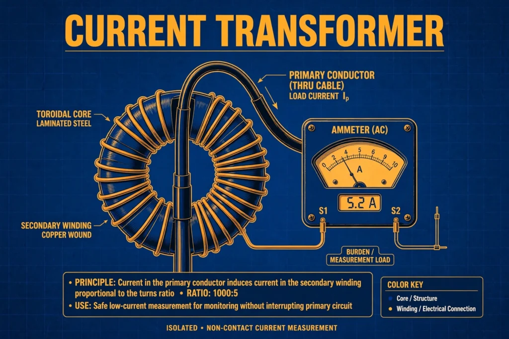
One more defining trait: a CT’s primary is connected in series with the load, and it has very few turns — often just a single conductor passing straight through the core. The secondary has many turns of fine wire and is always connected to a low-impedance device (the “burden”), such as a meter or relay coil.
How Does a Current Transformer Work? (Working Principle)
A current transformer works on the same fundamental law as every transformer: electromagnetic induction, governed by the ampere-turn balance. When alternating current flows through the primary conductor, it creates an alternating magnetic flux in the laminated steel core. That flux links the secondary winding and induces a current in it. Because the core’s magnetizing needs are tiny compared with the load current, the ampere-turns on both sides stay nearly equal: Primary ampere-turns = Secondary ampere-turns (N1 × I1 = N2 × I2)
This gives the simple ratio relationship: I2 = I1 × (N1/N2). A CT with 1 primary turn and 80 secondary turns and a 400 A primary current produces 400 × (1/80) = 5 A in the secondary. That is where the familiar 400/5 A nameplate rating comes from.
Unlike a power transformer, a current transformer normally operates with its secondary effectively short-circuited through the low impedance of the connected meter or relay. The secondary voltage stays very small — just enough to push the secondary current through the burden. This near-short-circuit operation is completely normal and by design.
The Golden Safety Rule: Never Open-Circuit a Live CT Secondary
This is the single most important thing to know about current transformers. If the secondary winding of an energized CT is left open-circuited — say, while a meter is being removed — the consequences are severe:
- With no secondary current flowing, there is nothing to oppose the primary magnetomotive force, so the entire primary current becomes magnetizing current.
- The core saturates deeply, and the flux waveform becomes sharply peaked.
- This induces extremely high voltage spikes across the open secondary terminals — easily reaching several kilovolts.
- The result can be insulation breakdown, arcing, damage to the CT, and a lethal shock hazard to anyone nearby.
For this reason, CT secondaries are always shorted with a shorting link before any connected meter or relay is disconnected for maintenance. Every panel with CTs has these shorting facilities built in, and every electrician working with instrument transformers learns this rule on day one.
Types of Current Transformers
Current transformers come in several construction styles, each suited to different installation needs:
1. Wound Current Transformer
The primary winding is wound with several turns around the core, just like a conventional transformer. Wound CTs are used for lower primary currents (typically below 200 A), where a single-turn primary would not give enough magnetizing force for accuracy. You will see them in small panels and metering cubicles.
2. Bar Current Transformer
Here the primary is a solid copper or aluminum bar that passes straight through the core — effectively a single-turn primary. Bar CTs handle medium to high currents and are common in switchgear and distribution panels, where the busbar itself becomes the primary simply by passing through the CT.
3. Toroidal (Window / Ring) Current Transformer
The core is a continuous ring (toroid) with the secondary winding distributed around it, and the primary conductor simply threads through the central window. There is no separate primary winding at all — the cable or busbar passing through is the primary. These are the most common type in new installations because they are compact, accurate, and easy to install around existing conductors.
4. Split-Core (Clamp-On) Current Transformer
A hinged version of the toroidal CT that can be opened, clamped around a live conductor, and closed again — no need to disconnect or thread the cable. Split-core CTs are the principle behind clamp meters and are ideal for retrofitting energy monitoring onto existing installations without shutdowns. If you use a clamp meter, you are already using a split-core CT; see our guide on multimeter uses for how these instruments fit into everyday electrical testing.
Metering vs Protection CTs
Beyond construction, CTs are divided by duty:
- Metering CTs are optimized for accuracy at normal load currents (accuracy classes like 0.2, 0.5, or 1.0). They are deliberately designed to saturate during heavy fault currents, which conveniently protects the delicate metering instruments from damage.
- Protection CTs must stay accurate during fault conditions, when currents can be 10–20 times normal. They use accuracy classes like 5P10 or 10P20 and are built with larger cores that resist saturation, because protective relays depend on them to “see” faults clearly.
Applications of Current Transformers
Energy Metering and Billing
Every commercial and industrial electricity meter that handles more than a few dozen amperes works through CTs. The meter measures the small secondary current and scales it by the CT ratio to compute the real energy consumed. Without CTs, utility billing for factories, malls, and large buildings would be impossible.
Protective Relaying
Protection relays — the intelligent devices that detect faults and command breakers to trip — get their current information from CTs. Overcurrent relays, differential relays, and earth-fault relays all rely on CT secondaries. The CT is essentially the “eyes” of the protection system: if it cannot see the fault current accurately, the relay cannot act correctly. This is why protection-class CTs are built to avoid saturation during faults.
Earth-Fault and Leakage Detection
A special arrangement called the core-balance (or zero-sequence) CT passes all three phase conductors through a single toroidal core. Under healthy conditions the currents cancel out; any residual current indicates an earth fault or leakage. This principle sits at the heart of sensitive earth-fault protection and residual-current devices.
Motor and Equipment Monitoring
CTs continuously monitor motor currents to detect overloads, phase loss, or stalled rotors. A rising current trend often warns of bearing wear or mechanical trouble long before failure, making CTs a staple of predictive maintenance programs.
Power Quality and Energy Management
Modern power analyzers and building-management systems use CTs (often split-core types for easy retrofit) to track consumption patterns, identify wasteful loads, and verify power-factor correction — all without interrupting supply.
FAQs
Why should a current transformer secondary never be open-circuited?
Because with the secondary open, no opposing secondary current flows, so the full primary current becomes magnetizing current. The core saturates and induces kilovolt-level spikes across the open terminals, which can destroy insulation, cause arcing fires, and fatally shock anyone nearby. Always short the secondary before disconnecting its instruments.
What is the difference between a CT and a PT?
A current transformer (CT) steps down current and is connected in series with the load; its secondary must never be open-circuited. A potential transformer (PT/VT) steps down voltage, is connected in parallel across the supply, and its secondary must never be short-circuited. They are mirror images in both connection and safety rules.
What does a 400/5 A rating on a CT nameplate mean?
It means that when 400 amperes flow in the primary, the secondary produces 5 amperes. The ratio (80:1 here) lets a standard 5 A meter display the true primary current when its scale is marked accordingly.
What is CT burden?
Burden is the total impedance of everything connected to the CT secondary — meters, relay coils, and connecting leads — usually expressed in volt-amperes (e.g., 5 VA, 10 VA, 15 VA). A CT only maintains its accuracy class if the actual connected burden does not exceed its rated burden.
What happens when a CT saturates?
Saturation occurs when the core cannot carry more magnetic flux — typically during heavy fault currents or with an excessive burden. The secondary waveform distorts and no longer tracks the primary proportionally, so meters under-read and relays may misoperate. Metering CTs are designed to saturate early (protecting meters); protection CTs are designed to resist it.
Can a current transformer step up current?
In theory a CT with more primary turns than secondary turns would step current up, but this is never done in practice. CTs are always used step-down, because their entire purpose is to reduce high primary currents to safe, measurable levels.
Conclusion
The current transformer is one of those quiet devices that modern electrical systems cannot function without. By stepping dangerous primary currents down to a safe, standardized secondary value, it makes accurate metering possible and gives protective relays the clear vision they need to guard equipment and people. Remember its construction types — wound, bar, toroidal, and split-core — the metering-versus-protection distinction, and above all the golden safety rule: never, ever open-circuit the secondary of an energized CT. With those fundamentals in place, you can confidently specify, install, and work around current transformers in any metering or protection application.