
Temperature is the most commonly measured physical quantity in industry. Furnaces, ovens, engines, chemical reactors, and even your home water heater all need to know how hot things are — and the sensor doing that job, more often than any other, is the thermocouple. It has no moving parts, needs no external power, survives brutal environments, and costs very little. From steel mills running at 1,600°C to food freezers at −40°C, thermocouples quietly report temperatures day after day.
Yet despite their simplicity, thermocouples are often misunderstood. How can two plain wires generate a voltage? Why are there so many types — K, J, T, E, N, R, S, B? And when should you choose a thermocouple over other temperature sensors? This guide answers all of that: what a thermocouple is, the physics behind it, the standard types and their temperature ranges, and where they are used in the real world.
What Is a Thermocouple?
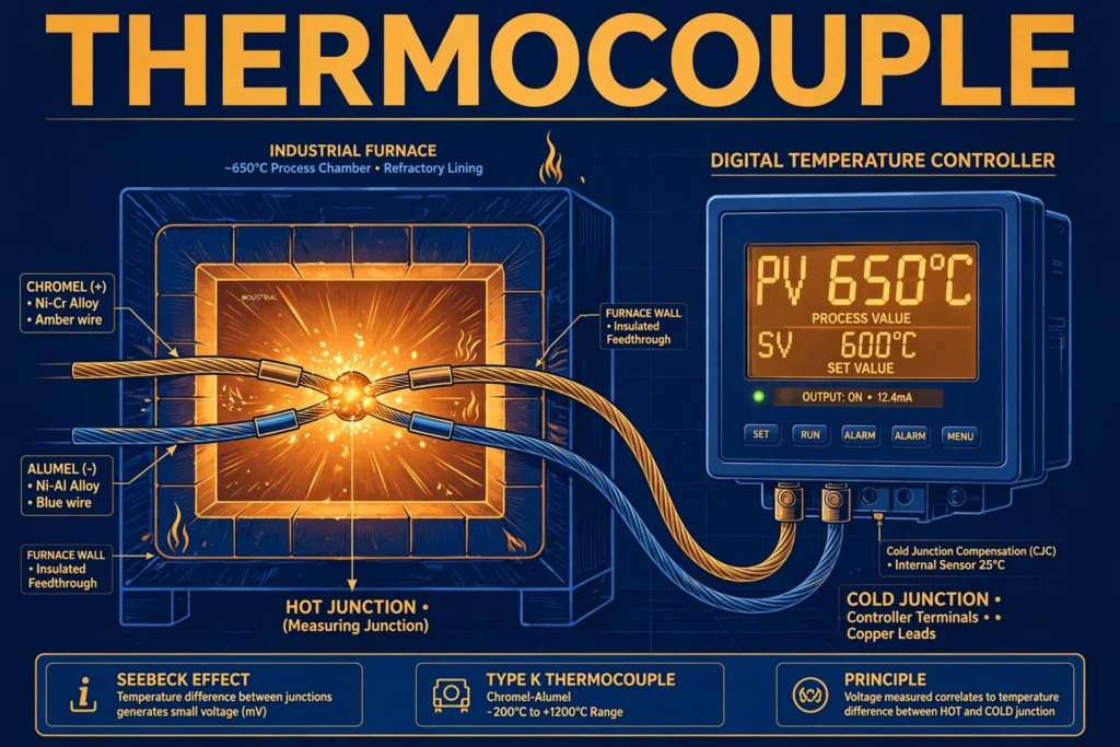
A thermocouple is a temperature sensor made by joining two wires of dissimilar metals at one end. That joined end is called the hot junction (or measuring junction) and is placed where the temperature needs to be measured. The other ends of the two wires — the cold junction (or reference junction) — connect to a measuring instrument. When the two junctions are at different temperatures, a small DC voltage appears across the free ends, and that voltage is directly related to the temperature difference.
The beauty of the device is its simplicity: no batteries, no electronics at the sensing point, just two wires and physics. A typical thermocouple generates only millivolts — a type K thermocouple, for example, produces roughly 41 microvolts per degree Celsius — so the measuring instrument must be a sensitive millivoltmeter or a dedicated thermocouple input module. In industrial automation, those inputs usually live inside a PLC, which reads the millivolt signal, applies cold-junction compensation, and converts it into a temperature the control system can act on.
Thermocouples are classified by the metal pair used, and each combination has a letter designation (K, J, T, and so on) with its own temperature range, accuracy, and best-use cases — covered in detail below.
Working Principle: The Seebeck Effect
The thermocouple works on the Seebeck effect, discovered in 1821 by the physicist Thomas Johann Seebeck. He found that when two different conductors are joined at both ends and the two junctions are kept at different temperatures, an electric current flows around the loop. In a thermocouple, we use only one junction at the hot end and measure the open-circuit voltage at the other end instead of letting current flow — but the underlying phenomenon is identical.
Here is what happens step by step:
- Two dissimilar metals meet. Different metals have different densities of free electrons. At the junction where they touch, electrons diffuse from one metal to the other, creating a tiny contact voltage.
- A temperature gradient drives the effect. When the measuring junction is hotter than the reference junction, the electron activity differs between the two ends, and a net electromotive force (EMF) appears across the free wire ends.
- Voltage tracks temperature difference. The generated voltage is approximately proportional to the difference in temperature between the hot and cold junctions — not the absolute temperature. Double the temperature difference, and you roughly double the millivolt output.
- The reference junction must be known. Because the output depends on the difference, the instrument must know the cold-junction temperature to compute the hot-junction temperature. Modern instruments measure the terminal temperature with a built-in sensor and add automatic cold-junction compensation (CJC).
A crucial practical point: the thermocouple’s voltage also depends on the entire temperature profile along the wires, but in practice the reading is dominated by the hottest junction — which is why proper installation places the measuring junction exactly where the temperature matters and keeps the lead wires away from other heat sources.
Polarity and Color Codes
Thermocouples are polarized: one leg is positive, the other negative, and swapping them inverts the reading. Manufacturers mark polarity with color-coded insulation and connectors, but be warned — color codes differ between standards (IEC, ANSI, and others use different schemes). Always verify against the standard your plant follows before wiring, especially when extending thermocouple leads.
Types of Thermocouples
Each thermocouple type is defined by its metal pair. Here are the types you will actually encounter:
Type K (Chromel–Alumel) — The Workhorse
The most widely used thermocouple in the world. Range: approximately −200°C to +1,260°C. Good accuracy, good oxidation resistance, and inexpensive. If someone says “thermocouple” without specifying, they usually mean type K. Used in furnaces, kilns, engines, and general industrial measurement.
Type J (Iron–Constantan)
Range: roughly −40°C to +750°C. The iron leg gives a high output signal, but iron oxidizes above about 550°C, so type J suits reducing or inert atmospheres and lower-temperature work better than type K. Common in plastics processing and older installations.
Type T (Copper–Constantan)
Range: about −200°C to +350°C. Excellent stability and accuracy at low and cryogenic temperatures, and highly resistant to moisture — making it the favorite for food processing, refrigeration, and laboratory work.
Type E (Chromel–Constantan)
The highest millivolt output per degree of the common base-metal types, which gives the best resolution for small temperature differences. Range: roughly −200°C to +900°C. Popular in cryogenics and applications needing fine sensitivity.
Type N (Nicrosil–Nisil)
Developed as an improved alternative to type K, with better stability and oxidation resistance at high temperatures. Range: about −200°C to +1,300°C. Increasingly chosen for demanding high-temperature service.
Types R, S, and B (Noble-Metal Thermocouples)
These use platinum–rhodium alloys and cover extreme temperatures — up to about 1,600–1,700°C. They are far more expensive and more fragile than base-metal types, so they are reserved for laboratory standards, semiconductor processing, and high-temperature furnaces where nothing else survives.
Quick Comparison
| Type | Metal Pair | Approx. Range | Typical Use |
|---|---|---|---|
| K | Chromel–Alumel | −200 to +1,260°C | General industry, furnaces |
| J | Iron–Constantan | −40 to +750°C | Plastics, low-temp industry |
| T | Copper–Constantan | −200 to +350°C | Food, refrigeration, labs |
| E | Chromel–Constantan | −200 to +900°C | Cryogenics, high sensitivity |
| N | Nicrosil–Nisil | −200 to +1,300°C | High-temp, stable service |
| R/S/B | Platinum–Rhodium | 0 to ~1,700°C | Labs, extreme heat |
Applications of Thermocouples
Industrial Furnaces, Kilns, and Ovens
This is the thermocouple’s home turf. Heat-treatment furnaces, ceramic kilns, glass tanks, and bakery ovens all use type K or N thermocouples to hold precise temperatures, often feeding PLC-based controllers that switch heaters on and off around the setpoint.
Gas Appliances and Flame Safety
The thermocouple in your gas water heater or furnace is a safety device: the pilot flame heats the junction, generating the millivolts that hold the gas valve open. If the flame goes out, the voltage collapses and the valve snaps shut — a beautifully simple fail-safe with no electronics involved.
HVAC and Refrigeration
Type T thermocouples monitor air ducts, chilled-water lines, and cold rooms, where their moisture resistance and low-temperature accuracy shine.
Automotive and Engines
Exhaust-gas temperature (EGT) probes in diesel engines and turbines are ruggedized thermocouples, helping engine controllers optimize combustion and protect turbochargers from overheating.
3D Printers and Food Industry
A 3D printer’s hotend temperature is typically read by a small thermocouple or thermistor, and food plants use sealed type T probes to verify cooking and chilling temperatures for safety compliance.
Test and Measurement
Many digital multimeters include a temperature function with a bead-type thermocouple probe — handy for checking heat sinks, motor windings, and HVAC components in the field. For more on what these instruments can do, see our overview of multimeter uses.
FAQs
How is a thermocouple different from an RTD or thermistor?
All three measure temperature, but differently. A thermocouple generates its own millivolt signal from the Seebeck effect, needs no excitation power, and handles the widest temperature range — but with moderate accuracy. An RTD (resistance temperature detector, usually platinum Pt100) changes resistance with temperature and offers the best accuracy and stability in the −200 to +600°C band, at higher cost. A thermistor is a cheap, highly sensitive resistor for narrow ranges near room temperature. Choose thermocouples for wide ranges, harsh conditions, and low cost; RTDs for precision.
Why are there so many thermocouple types?
Because no single metal pair is best everywhere. The choice balances temperature range, chemical environment (oxidizing vs reducing), accuracy, response time, and cost. Type K covers most general needs; types J and T serve lower-temperature niches; noble-metal types R, S, and B survive temperatures that would destroy base-metal wires.
Do thermocouples need an external power supply?
No — the sensing junction itself is self-powered; the Seebeck effect generates the signal voltage from heat alone. (The measuring instrument, of course, needs its own power.) This self-powered nature is why thermocouples keep working in remote or hazardous locations.
Can I extend thermocouple wires with ordinary copper wire?
No — and this is the most common installation mistake. Extending with copper creates two new unintended junctions (thermocouple-to-copper at each end) that add error voltages. Always extend with proper thermocouple extension wire of the same type (or matched compensating cable), keeping polarity correct all the way to the instrument.
What is cold-junction compensation?
Since a thermocouple measures the difference between its hot and cold junctions, the instrument must account for the cold junction’s temperature. Cold-junction compensation means the instrument measures its own terminal temperature and mathematically adds the equivalent voltage, so the displayed reading reflects the true hot-junction temperature regardless of ambient conditions.
How long do thermocouples last?
It depends on the environment. In clean, moderate conditions a thermocouple can last years. In extreme heat, corrosive atmospheres, or with constant thermal cycling, the metals gradually degrade (drift), and the sensor should be recalibrated or replaced on a schedule — critical in processes where accuracy affects product quality or safety.
Conclusion
The thermocouple earns its place as industry’s favorite temperature sensor through a rare combination: extreme simplicity, no need for power at the sensing point, an enormous temperature range, and low cost. The Seebeck effect turns two joined wires into a reliable thermometer; the standard letter types (K, J, T, E, N, and the noble-metal R/S/B family) let you match the sensor to the job; and proper installation — correct polarity, matched extension wire, and cold-junction compensation — keeps readings trustworthy. Whether you are tuning a furnace, safeguarding a gas appliance, or logging temperatures into a PLC, understanding the thermocouple means understanding the most measured quantity in the industrial world.