
A light dimmer, a motor speed controller, a battery charger, and a high-voltage DC transmission station all share one component: a switch that can turn on thousands of amps with a tiny pulse of current, and then stay on by itself until the current stops. That component is the thyristor — and its most common form, the silicon controlled rectifier, or SCR, has been the workhorse of power electronics since General Electric introduced it commercially in 1957.
This guide explains what a thyristor is, how its four-layer structure works, how to read its characteristic curve, how it is turned on and off, and where it is used — with a worked phase-control example you can check with a calculator. If you are new to semiconductor switches, start with our guides to what a semiconductor is and what a diode is, and our transistor guide explains the device the thyristor is built from.
What Is a Thyristor (SCR)?
A thyristor is a four-layer semiconductor switching device, and the silicon controlled rectifier (SCR) is its original and most widely used member. The name says what it does: it is made of silicon, it is controlled by a gate signal, and once it is on it behaves like a rectifying diode. Like a diode, it conducts current in one direction only. Unlike a diode, it will not conduct at all until it is told to — a small current pulse into its third terminal, the gate, switches it on.
The SCR has three terminals: the anode (A), the cathode (K), and the gate (G). It is a switching device only — it cannot amplify a signal the way a transistor can. Its strength is power: a single SCR can switch thousands of volts and thousands of amps, far beyond what a single transistor or MOSFET of the same size can handle, which is why SCRs still dominate heavy-duty power control even though transistors are faster and easier to drive.
Thyristor Structure: Four Layers, Three Junctions
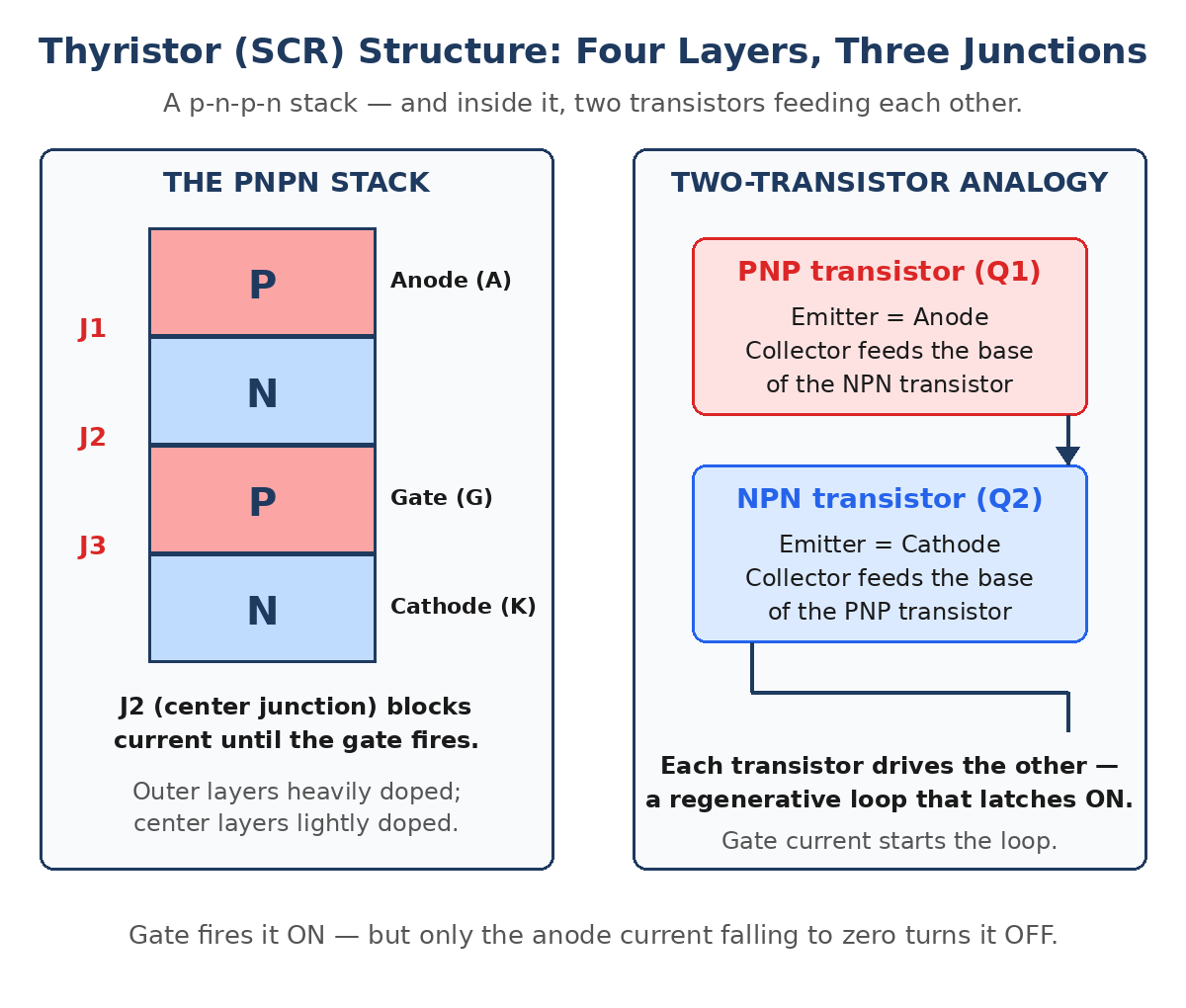
Inside, an SCR is a stack of four alternating layers of silicon: p-n-p-n. That stack creates three p-n junctions, called J1, J2, and J3. The outer layers are heavily doped and the two center layers are lightly doped. The anode connects to the top p-layer, the cathode to the bottom n-layer, and the gate connects to the center p-layer, next to the cathode.
The easiest way to understand the stack is the two-transistor analogy: think of the four layers as a PNP transistor (Q1) and an NPN transistor (Q2) connected back to back, so that each transistor’s collector feeds the other transistor’s base. When the gate injects a little current into the base of the NPN transistor, it turns on and feeds current into the base of the PNP transistor, which turns on and feeds even more current back into the NPN transistor. The loop feeds on itself — a regenerative process — and the whole device snaps on in a fraction of a microsecond. That is why the SCR is called a latching switch: once the loop is running, it keeps itself on.
How an SCR Works: The Three Modes
An SCR has three operating modes, and the state of the center junction J2 decides which one you are in:
- Reverse blocking mode: the anode is negative relative to the cathode. Junctions J1 and J3 are reverse-biased and block current, while J2 is forward-biased. Only a tiny reverse leakage current flows — the SCR behaves like a reverse-biased diode. It blocks until the reverse voltage reaches the reverse breakdown voltage (VBR), which must never be exceeded in a real circuit.
- Forward blocking mode: the anode is positive relative to the cathode, but no gate signal is applied. Now J2 is reverse-biased and blocks the current, while J1 and J3 are forward-biased. The SCR is off, blocking the full supply voltage, with only a small forward leakage current flowing. It stays off until either the voltage rises past the forward breakover voltage (VBO) or a gate pulse arrives.
- Forward conduction mode: the gate pulse fires the regenerative loop, J2 breaks down, and the SCR conducts heavily with only about 1–2 V across it — the forward voltage drop of a conducting SCR. The gate can now be removed; the device stays on by itself.
That last point is the key difference from a transistor. A transistor needs continuous base current to stay on. An SCR needs only a brief gate pulse — a few microseconds is enough — and then it latches. The gate loses all control after turn-on. The only way to turn an SCR off is to bring the anode current down to zero (or below the holding current), which in AC circuits happens naturally at every zero crossing of the supply.
The SCR I–V Characteristic Curve
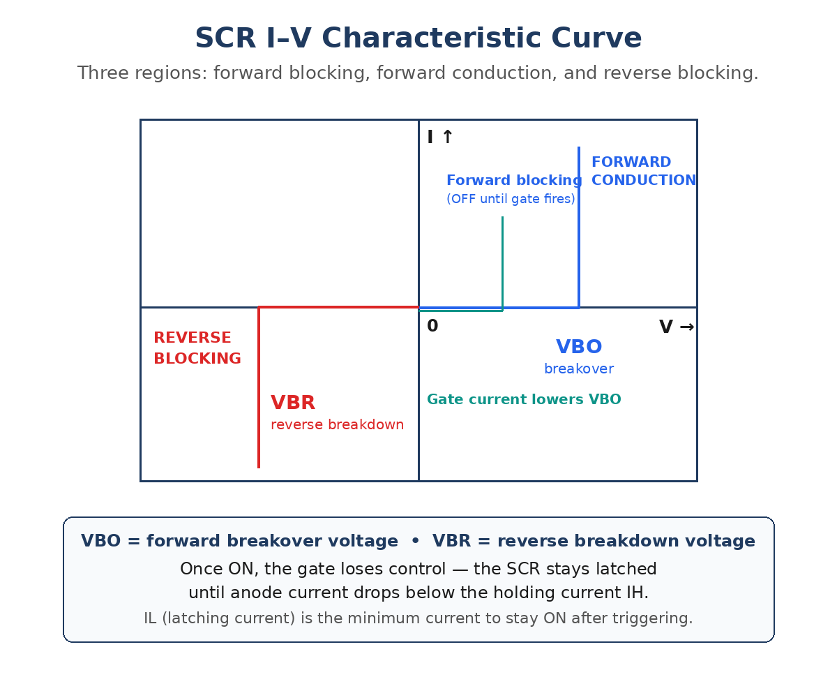
The current-voltage curve of an SCR has the same three regions as its three modes. In forward blocking, the curve runs almost flat along the voltage axis — voltage rises, current stays near zero — until it reaches VBO, the forward breakover voltage. There the curve turns sharply upward: the device has broken over and is now in forward conduction, where a large current flows with only a small voltage across the device. Apply gate current and VBO drops, so the SCR can be fired at a much lower voltage — that is how phase control works.
In the reverse direction the curve is flat until VBR, the reverse breakdown voltage, where it turns sharply downward into reverse conduction. Reverse breakdown is destructive in most SCRs and must be avoided by choosing a device with a voltage rating well above the circuit’s peak voltage. Two current limits complete the picture: the latching current (IL) is the minimum anode current needed to keep the SCR on immediately after the gate pulse ends, and the holding current (IH) is the minimum current needed to keep it on at all — below IH, the device drops out of conduction and turns off. Both are typically a few milliamps to a few tens of milliamps.
How to Turn an SCR On and Off
There are five ways to turn an SCR on, but only one of them is used in normal design:
- Gate triggering (normal method): a short current pulse into the gate while the anode is positive. This is the controlled, repeatable method every practical circuit uses.
- Voltage triggering: raising the anode voltage past VBO. This works, but it is uncontrolled and can damage the device — it is a failure mode, not a design method.
- dv/dt triggering: a fast-rising anode voltage can capacitively couple enough current into the gate to fire the device. Designers prevent this by keeping the rate of voltage rise below the datasheet dv/dt rating, sometimes with an RC snubber across the device.
- Temperature triggering: high temperature increases leakage current until the device fires by itself. This is another failure mode to design against, not a method to use.
- Light triggering: some SCRs (light-activated SCRs, or LASCRs) fire when light hits the gate junction — used in high-voltage applications where electrical isolation matters.
Turning an SCR off is harder than turning it on, because the gate cannot do it. The standard methods all reduce the anode current below the holding current: natural commutation, where the AC supply itself brings the current to zero every half-cycle; forced commutation, where a capacitor or a second switch diverts the current; and reverse-biasing the device briefly. This is exactly why SCRs are so natural in AC circuits and so awkward in DC circuits — in a DC circuit, something extra must be built to force the current to zero.
Key SCR Ratings
| Rating | Symbol | Meaning | Typical Range |
|---|---|---|---|
| Repetitive peak off-state voltage | VDRM | Maximum forward voltage the device can block repeatedly | 50–8,000 V |
| Repetitive peak reverse voltage | VRRM | Maximum reverse voltage the device can block repeatedly | 50–8,000 V |
| Average on-state current | IT(AV) | Maximum average current in conduction | 1 A to over 1,000 A |
| Surge current | ITSM | One half-cycle surge the device can survive | 10× rated current or more |
| Gate trigger current | IGT | Minimum gate current that reliably fires the device | 0.2–200 mA |
| Holding current | IH | Minimum anode current that keeps the device on | 1–50 mA |
| Critical dv/dt | dv/dt | Fastest voltage rise that will not fire the device | 50–1,000 V/µs |
Always choose an SCR with a voltage rating comfortably above the highest peak voltage in the circuit — a common rule is at least twice the peak supply voltage — and a current rating above the worst-case load current, including surges. The datasheet values VDRM, IT(AV), and ITSM are the three numbers to check first.
Worked Example: Phase Control of a Heater
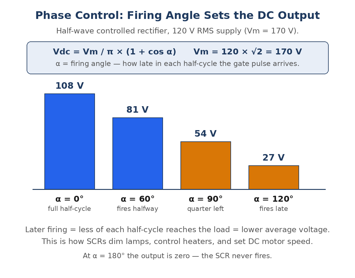
The classic SCR application is phase control: firing the SCR partway through each AC half-cycle so the load receives only part of the available power. For a half-wave controlled rectifier feeding a resistive load, the average DC output voltage depends on the firing angle α — the delay, in degrees, between the start of the half-cycle and the gate pulse:
Vdc = (Vm / π) × (1 + cos α), where Vm is the peak supply voltage.
Take a 120 V RMS supply, so Vm = 120 × √2 = 170 V, and Vm / π = 54.1 V. At α = 0° the SCR fires immediately and the load gets the full half-wave: Vdc = 54.1 × (1 + 1) = 108 V. Fire halfway through, at α = 60°, and Vdc = 54.1 × (1 + 0.5) = 81 V. At α = 90°, Vdc = 54.1 × 1 = 54 V. At α = 120°, Vdc = 54.1 × 0.5 = 27 V. At α = 180° the SCR never fires and the output is zero. One small gate pulse, moved earlier or later in the cycle, smoothly controls the power from full to nothing — that is how SCR lamp dimmers, heater controllers, and DC motor speed controls work.
The Thyristor Family
The SCR is only one member of the thyristor family. The others solve the SCR’s limitations — mainly that it conducts in one direction only and cannot be turned off by its gate:
- TRIAC: two SCRs in antiparallel in one package, so it conducts in both directions. The standard choice for AC lamp dimmers and small motor speed controls.
- DIAC: a two-terminal device that conducts in both directions once the voltage across it passes its breakover voltage. Often used to trigger a TRIAC’s gate.
- GTO (gate turn-off thyristor): an SCR that can be turned off by a negative gate pulse, so it works in DC circuits without forced commutation. Used in traction and medium-power drives.
- IGCT (integrated gate-commutated thyristor): a faster, harder-driven GTO for very high power — megawatt drives and grid equipment.
Where Thyristors Are Used
- Controlled rectifiers: converting AC to variable DC for battery chargers, electroplating, and DC motor drives. Our variable frequency drive guide covers the modern AC-side counterpart of this job.
- AC power control: lamp dimmers, heater controllers, and fan speed controls using phase control.
- HVDC transmission: converter stations that link asynchronous AC grids use stacks of high-voltage thyristors to convert gigawatts between AC and DC.
- Overvoltage protection: a crowbar circuit fires an SCR across the supply when the voltage rises too high, blowing a fuse and protecting the load behind it.
- Soft starters and solid-state switches: switching large AC loads without the arcing and wear of mechanical contacts.
SCR vs Transistor vs MOSFET
| Feature | SCR (Thyristor) | Transistor | MOSFET |
|---|---|---|---|
| Turn-on | Gate pulse (latches on) | Continuous base current | Gate voltage |
| Turn-off | Current must fall below IH | Remove base current | Remove gate voltage |
| Conduction direction | One way only | One way | One way (body diode reverse) |
| Can amplify | No — switching only | Yes | Yes |
| Power handling | Very high (kV, kA) | Medium | High, but lower than SCR |
| Switching speed | Slow (µs–ms) | Fast | Very fast (ns) |
| Best for | Heavy AC power control | Amplification, switching | Fast switching, SMPS |
Frequently Asked Questions
What is the difference between a thyristor and an SCR?
Almost none in everyday use. “Thyristor” is the family name for four-layer p-n-p-n switching devices; the SCR (silicon controlled rectifier) is the original and most common member of that family. Engineers usually say “thyristor” and “SCR” to mean the same device.
Why does an SCR stay on after the gate signal is removed?
Because of the regenerative two-transistor loop inside it. Once the gate starts the loop, the PNP and NPN transistors keep feeding each other’s bases, so the device sustains its own conduction. It only turns off when the anode current falls below the holding current.
Can an SCR be turned off by the gate?
No — a standard SCR cannot. The gate can only turn it on. To turn it off you must bring the anode current below the holding current, which in AC circuits happens naturally at each zero crossing. The GTO thyristor is the family member that can be turned off by its gate.
What is the firing angle in SCR phase control?
The firing angle α is the delay, measured in degrees of the AC cycle, between the start of a half-cycle and the gate pulse that fires the SCR. A small angle delivers almost the full half-cycle to the load; a large angle delivers only a small part of it. The average output voltage follows Vdc = (Vm / π) × (1 + cos α).
Where are SCRs still used today?
Everywhere heavy AC power must be controlled cheaply and reliably: lamp dimmers, heater controls, battery chargers, DC motor drives, soft starters, overvoltage crowbar protection, and high-voltage DC transmission converter stations. Transistors and IGBTs have taken over fast switching, but no other single device matches the SCR’s combination of voltage, current, and cost in bulk power control.
Conclusion
The thyristor is a beautifully simple idea: four layers of silicon that form two transistors feeding each other, so a tiny gate pulse latches the device on and it stays on until the current stops. That latching behavior is both its strength and its limitation — it makes the SCR unbeatable for AC power control, where the supply turns it off for free every half-cycle, and awkward in DC circuits, where extra commutation is needed. With its three modes, its VBO and VBR limits, and its phase-control formula Vdc = (Vm / π) × (1 + cos α), you can now read an SCR datasheet, design a simple dimmer or charger, and understand why this 1957 device still runs the heavy end of power electronics. For a deeper tutorial with more on the two-transistor model and the characteristic curves, see Thyristor or Silicon Controlled Rectifier (SCR) on Electrical4U.