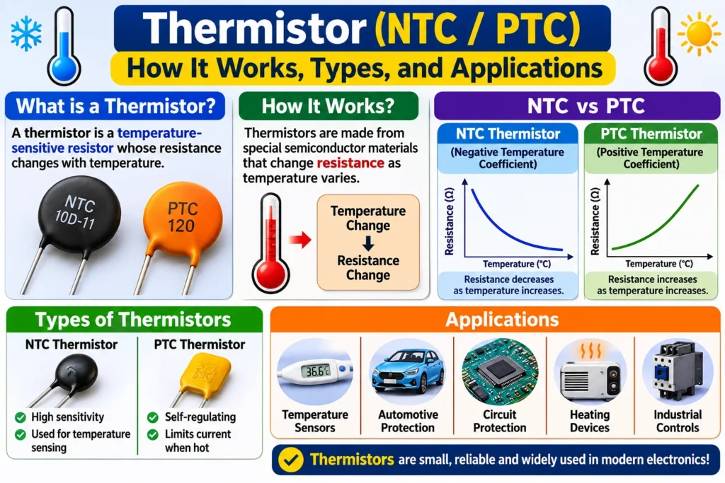

A thermistor is a resistor whose resistance changes a lot with temperature. That simple property makes it one of the most useful temperature sensors in electronics: it is cheap, small, fast, and easy to read with a microcontroller. Thermistors protect batteries from overheating, measure the temperature inside 3D printers, control fans, and limit inrush current in power supplies. There are two main kinds: NTC thermistors, whose resistance falls as temperature rises, and PTC thermistors, whose resistance rises as temperature rises. This guide explains how both work, the formulas you need to use them, and where each type belongs.
What Is a Thermistor?
A thermistor is a temperature-sensitive resistor made from a ceramic semiconductor, usually a metal oxide such as manganese, nickel, or cobalt oxide. Its name comes from thermal resistor. Unlike an ordinary resistor, which is designed to keep its value stable, a thermistor is designed so that its resistance changes in a predictable way with temperature. A circuit measures that resistance, often through a voltage divider, and converts it into a temperature reading. Thermistors are used for temperature measurement, temperature compensation, and overcurrent protection, and they work best over a limited range, typically -50 to 150 degrees C for NTC types.
NTC vs PTC Thermistors
The two types behave in opposite ways. An NTC (negative temperature coefficient) thermistor has a resistance that falls as temperature rises, often by several percent per degree C. It is the common type for temperature measurement. A PTC (positive temperature coefficient) thermistor has a resistance that rises as temperature rises, and above a switching temperature, called the Curie temperature, its resistance jumps by several orders of magnitude. That sharp jump makes PTC thermistors useful as self-resetting fuses and heaters, rather than as precise thermometers.
How a Thermistor Works
A thermistor works because the number of charge carriers in its semiconductor material changes with temperature. In an NTC thermistor, heat frees more carriers, so resistance falls. In a PTC thermistor made from doped barium titanate, resistance stays low until the Curie temperature, then the crystal structure changes and resistance climbs steeply. The thermistor itself does not output a temperature; a circuit must measure its resistance and convert it. The usual circuit is a voltage divider: the thermistor is placed in series with a fixed resistor across a supply, and the voltage at the junction is read by an analog-to-digital converter.
The B-Parameter Formula and a Worked Example
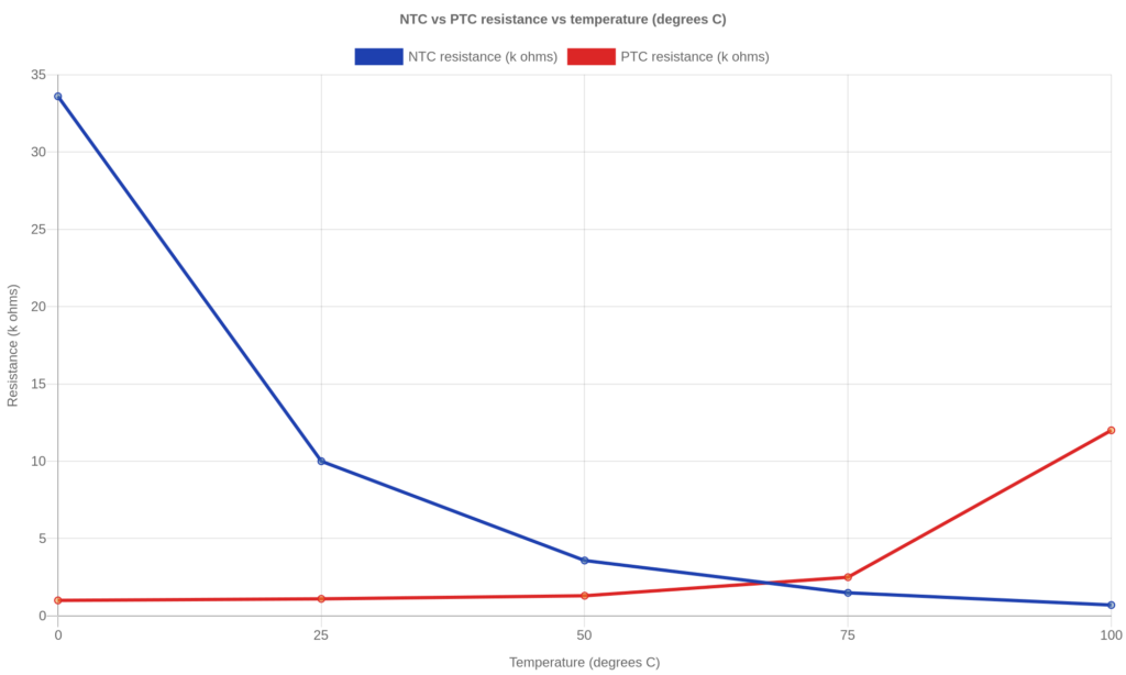
The resistance of an NTC thermistor follows the B-parameter equation: R = R25 x exp[B x (1/T – 1/T25)], where R25 is the resistance at 25 degrees C, B is the material constant in kelvin, and T is the absolute temperature in kelvin. Worked example: a 10 k ohm thermistor with B = 3950 K at 50 degrees C (323.15 K). 1/323.15 – 1/298.15 = -0.000260, times 3950 gives -1.027, and exp(-1.027) = 0.358, so R = 10,000 x 0.358 = 3,580 ohms. The same formula gives about 33,600 ohms at 0 degrees C and about 700 ohms at 100 degrees C, which shows how fast the resistance changes. For the best accuracy, use the Steinhart-Hart equation instead: 1/T = A + B x ln(R) + C x (ln R) cubed, with A, B, and C taken from the datasheet.

Reading a Thermistor with a Voltage Divider
In a voltage divider, the output voltage is Vout = Vin x R_thermistor / (R_fixed + R_thermistor). With a 5 V supply, a 10 k ohm fixed resistor, and the thermistor above at 50 degrees C (3,580 ohms), Vout = 5 x 3,580 / 13,580 = 1.32 V. A microcontroller reads that voltage and converts it back to temperature using the B-parameter or Steinhart-Hart equation. Choose the fixed resistor close to the thermistor resistance at the middle of your measuring range for the best sensitivity. Keep the current small, usually under 1 mA, because the thermistor heats itself when current flows through it, and self-heating makes the reading too high.
Types and Construction
Thermistors come in several shapes. Bead thermistors are tiny glass-coated beads for fast response in air or liquid. Disc and chip thermistors are used on circuit boards for temperature compensation and inrush limiting. Probe thermistors are sealed in a metal tube for use in water, food, or industrial pipes. Surface-mount (SMD) thermistors solder directly onto a board next to the part they protect, such as a battery or a processor. PTC thermistors are also made as resettable fuses (polyswitches) that trip when current is too high and reset when they cool down.
Applications of Thermistors
NTC thermistors measure temperature in battery packs, 3D printer hot ends, coffee machines, air conditioners, and medical thermometers. They also limit inrush current: a cold NTC has high resistance, so it limits the surge when a power supply is switched on, then its resistance falls as it warms up. PTC thermistors protect motors, transformers, and circuits from overcurrent, and they act as self-regulating heaters in car mirrors and small appliances. Both types are used for temperature compensation in oscillators and in charging circuits, where the charging voltage must fall as the battery warms up.
How to Choose and Test a Thermistor
Start with the range and the resistance at 25 degrees C, usually 1 k, 10 k, or 100 k ohms. Check the B value, the tolerance, and the maximum power rating. Then check the package: a bead for fast air sensing, a probe for liquids, an SMD part for a board. To test a thermistor, measure its resistance with a multimeter at room temperature and compare it with the datasheet value, then warm it gently with your fingers or a hair dryer and watch the resistance fall for an NTC or rise for a PTC. If the resistance does not change, the part is open or the wrong type. Always use the datasheet curve or the Steinhart-Hart coefficients for the final temperature calculation, not a single B value, when accuracy matters.
| Feature | NTC thermistor | PTC thermistor |
|---|---|---|
| Resistance vs temperature | Falls as temperature rises | Rises as temperature rises |
| Typical resistance at 25 C | 1 k to 100 k ohms | 100 ohms to 10 k ohms |
| Main use | Temperature measurement | Overcurrent protection, heating |
| Accuracy | High, 0.1 to 1 C possible | Low for measurement |
| Range | -50 to 150 C typical | -40 to 150 C, sharp rise above Curie point |
| Examples | Battery pack, 3D printer, HVAC | Resettable fuse, motor protection |
Related reading: Types of Sensors: A Complete Guide to How Sensors Work and Where They Are Used
Related reading: What Is a Resistor and How Does It Work?
Frequently Asked Questions
What is the difference between an NTC and a PTC thermistor?
An NTC thermistor has a negative temperature coefficient: its resistance falls as temperature rises. A PTC thermistor has a positive temperature coefficient: its resistance rises as temperature rises, and it jumps sharply above its Curie temperature. NTC types are used mainly for temperature measurement, while PTC types are used mainly for protection and heating.
How do you calculate temperature from a thermistor?
Measure the thermistor resistance, then use the B-parameter equation or the Steinhart-Hart equation to convert resistance to temperature in kelvin, and subtract 273.15 to get degrees C. Most microcontrollers do this in code, using the coefficients from the thermistor datasheet, or a lookup table of resistance against temperature.
Can a thermistor measure below zero or above 150 degrees C?
Some NTC thermistors work from -50 to 300 degrees C, but accuracy falls at the extremes and the resistance becomes very large or very small. For high temperatures, a thermocouple or an RTD is usually a better choice, while a thermistor is best between about -40 and 150 degrees C.
Why does my thermistor reading drift?
Self-heating is the most common cause: too much current warms the thermistor above the temperature it is measuring. Use a larger fixed resistor, read the voltage quickly, or switch the divider off between readings. Poor contact, moisture, and an incorrect B value also cause errors.
Is a thermistor a sensor or a transducer?
It is both. A thermistor senses temperature and converts heat into a resistance change, which is a form of energy conversion. That makes it a temperature sensor and a transducer at the same time.
Conclusion
A thermistor turns temperature into a resistance that any simple circuit can read. NTC types fall in resistance as they warm up and suit temperature measurement and inrush limiting, while PTC types rise in resistance and suit protection and self-regulating heat. Choose the resistance, B value, and package for your range, use the B-parameter or Steinhart-Hart equation to convert resistance to temperature, and keep the measuring current low to avoid self-heating. For a full technical reference on thermistors, see Wikipedia: https://en.wikipedia.org/wiki/Thermistor