
Imagine switching on a large industrial motor in a factory. Three wires may carry electrical power to the motor, and each wire has a changing voltage that reaches its peak at a different time. This timing relationship is called phase. It is one of the most important concepts in AC electrical systems.
For a beginner, the word “phase” can be confusing. An electrician may say “single-phase supply,” an engineer may discuss “three-phase power,” and a technician may check whether the phases are correctly sequenced. All of these terms are related, but they describe different parts of the same electrical concept.
Understanding Phase Meaning helps you understand AC voltage, current, motors, generators, transformers, distribution systems, and electrical measurements. It also makes topics such as phase angle, phase sequence, phase difference, and power factor easier to understand.
In this guide, you will learn what phase means in electrical engineering, how phase works, its main types, important components, advantages and disadvantages, applications, troubleshooting methods, and future developments.
What is Phase?
In electrical engineering, phase describes the position or timing of an alternating electrical waveform within its cycle.
An AC voltage does not remain constant. It continuously rises, falls, changes direction, and repeats its pattern. The position of the waveform at a particular moment is called its phase.
A simple way to understand phase is to imagine two people running around a circular track. If both start together, they are in the same position. If one runner is ahead, there is a difference in position.
Electrical waveforms behave in a similar way.
Simple Definition
Phase is the relative position of an AC waveform with respect to time or another waveform.
Phase is normally measured as an angle in degrees.
One complete AC cycle represents:
360°
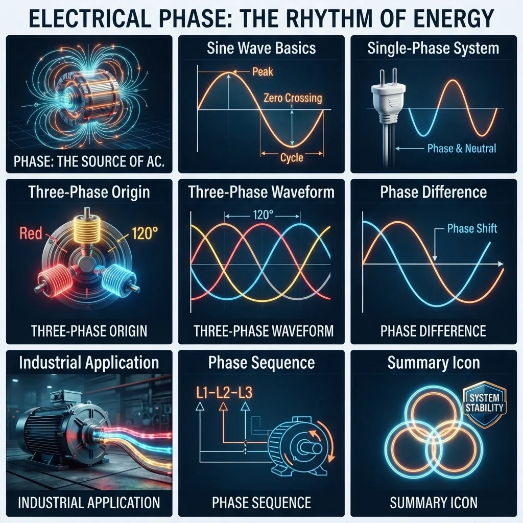
Important points in one ideal sine-wave cycle are:
- 0° — starting point
- 90° — positive peak
- 180° — zero crossing
- 270° — negative peak
- 360° — cycle completed
After 360°, the waveform starts another cycle.
Practical Example
Suppose two AC voltages have the same frequency.
If both reach their positive peaks at the same time, they are in phase.
If one reaches its peak before the other, they have a phase difference.
For example, if one waveform leads another by 90°, their phase difference is:
90°
This basic idea is essential when studying AC circuits and electrical machines.
Phase Working Principle
The phase working principle is based on the changing position of an AC waveform during each electrical cycle.
To understand it easily, think of a rotating wheel. A point on the wheel continuously changes position as the wheel rotates. A sine wave can be represented using a similar circular motion.
Step-by-Step Working
- An AC source produces a changing voltage.
- The voltage follows a repeating waveform, usually a sine wave.
- One complete waveform cycle represents 360°.
- The waveform’s position at any instant represents its phase.
- When two waveforms are compared, their timing relationship produces a phase difference.
- This phase relationship affects current, voltage, power, and motor operation.
Phase and Time
Phase and time are closely related.
For an AC system:
Phase angle = Time difference / Period × 360°
For example, if one waveform is delayed by one-quarter of a cycle, its phase difference is:
90°
This is why phase angle is often used instead of simply saying that one waveform occurs earlier or later.
Phase Lead and Phase Lag
When one waveform reaches the same point earlier than another, it is said to lead.
When it reaches that point later, it is said to lag.
For example:
- Voltage leads current → current lags voltage.
- Current leads voltage → voltage lags current.
This relationship is especially important in inductive and capacitive circuits.
Types / Classification of Phase
Electrical systems are commonly classified by the number and relationship of their phases.
1. Single Phase
A single-phase system uses one AC voltage waveform.
It is widely used in homes, small offices, shops, and light commercial installations.
A typical single-phase supply has:
- Phase conductor
- Neutral conductor
- Protective earth conductor where required
Single-phase systems are suitable for lighting, household appliances, computers, fans, and small motors.
2. Three Phase
A three-phase system uses three AC waveforms.
The three waveforms have the same frequency and magnitude under balanced conditions, but they are separated by 120 electrical degrees.
Three-phase power is widely used in:
- Factories
- Large buildings
- Industrial motors
- Pumps
- Compressors
- Generators
- Power distribution systems
Because power delivery is more continuous, three-phase systems are highly useful for industrial equipment.
3. Two Phase
Two-phase systems use two alternating waveforms with a phase relationship between them.
True two-phase power systems are uncommon in modern power distribution. However, the concept can still appear in electrical engineering theory and certain specialized applications.
It should not be confused with a split-phase residential system.
4. Split Phase
A split-phase system is commonly used in residential electrical systems in some countries.
It provides two voltage sources that are approximately 180° apart.
This arrangement allows both lower-voltage loads and higher-voltage loads to be supplied from the same system.
5. Balanced Phase
A balanced three-phase system has phase voltages or currents with equal magnitudes and equal angular separation.
For a balanced three-phase system:
- Magnitudes are equal.
- Phase separation is 120°.
- The system operates efficiently.
- Neutral current can ideally become zero for balanced loads.
Balanced systems are desirable in industrial installations.
6. Unbalanced Phase
A three-phase system becomes unbalanced when phase voltages or currents are not equal or their phase relationships are disturbed.
Unbalance can result from:
- Unequal loads
- Faults
- Loose connections
- Supply problems
- Uneven distribution of single-phase loads
Severe voltage unbalance can cause overheating in motors.
Main Components Related to Phase
Phase itself is not a physical component. It is an electrical relationship. However, several components create, carry, measure, or control phase relationships.
AC Generator
An AC generator produces alternating voltage.
In a three-phase generator, three sets of windings produce three electrical waveforms separated by 120°.
Phase Conductors
Phase conductors carry AC power from the source to electrical loads.
In a three-phase system, they are commonly identified as:
- L1
- L2
- L3
Exact conductor identification depends on the applicable electrical code and installation practice.
Neutral Conductor
The neutral provides a return path in many systems and can carry current from unbalanced single-phase loads.
In a balanced three-phase system, neutral current can be very low or theoretically zero.
Electrical Load
The load consumes electrical energy.
Examples include:
- Motors
- Heaters
- Lamps
- Transformers
- Electronic equipment
The type and balance of the load can affect phase currents.
Phase Meter
A phase meter or phase-angle measurement instrument can help technicians determine the relationship between electrical quantities.
Modern power-quality instruments can measure voltage, current, phase angle, harmonics, and other parameters.
Phase Sequence Meter
A phase sequence meter determines the order in which three-phase voltages reach their corresponding positions.
Correct phase sequence is especially important for three-phase motors.
Advantages of Phase Systems
Understanding phase relationships provides several practical benefits.
Better Power Transmission
Three-phase systems can transmit large amounts of electrical power efficiently.
Smooth Motor Operation
Three-phase motors produce a rotating magnetic field naturally, allowing smooth and efficient operation.
Efficient Industrial Distribution
Three-phase power is well suited to factories and large commercial facilities.
Easier Motor Direction Control
Changing the phase sequence of a three-phase motor can change its direction of rotation.
Better Load Distribution
Loads can be distributed across different phases to improve system balance.
Reduced Conductor Requirements
For large three-phase power systems, power can be transmitted efficiently with less conductor material compared with equivalent single-phase arrangements.
Improved System Performance
Correct phase relationships help electrical equipment operate within its intended design conditions.
Disadvantages / Limitations of Phase Systems
Phase systems also have limitations that technicians must consider.
Phase Imbalance
Unequal loading can create current imbalance and equipment heating.
Phase Sequence Problems
Incorrect phase sequence can cause a three-phase motor to rotate in the wrong direction.
Troubleshooting Can Be Complex
A fault affecting one phase may require careful voltage and current measurements.
Higher Installation Complexity
Three-phase systems require more careful design, protection, identification, and testing than basic single-phase circuits.
Phase-Related Faults
Common faults include:
- Phase-to-phase faults
- Phase-to-ground faults
- Open-phase conditions
- Incorrect phase sequence
- Voltage imbalance
Proper protection and testing are essential.
Phase Applications
The phase applications are found throughout modern electrical systems.
Home Applications
Single-phase systems commonly supply:
- Lights
- Fans
- Refrigerators
- Washing machines
- Computers
- Television systems
- Small air conditioners
The exact supply arrangement depends on the country’s electrical distribution system.
Industrial Applications
Three-phase systems are extremely important in industry.
They supply:
- Induction motors
- Pumps
- Compressors
- Conveyor systems
- Machine tools
- Industrial HVAC systems
- Large transformers
Power Generation
Power stations commonly generate electrical energy using three-phase generators.
The generated power is then transformed and transmitted through electrical networks.
Power Distribution
Three-phase distribution systems supply commercial buildings, industrial plants, and other large loads.
Transformers change voltage levels while maintaining the system’s phase relationships.
Renewable Energy
Solar and wind energy systems may use power electronic converters to connect generated electricity to AC grids.
These converters carefully control phase, frequency, voltage, and current.
Modern Technology
Phase control is important in:
- Variable frequency drives
- Solar inverters
- Battery energy storage
- Electric vehicle charging
- Smart grids
- Power-quality monitoring
- Industrial automation
Phase vs Neutral: What Is the Difference?
Beginners often confuse phase and neutral.
| Feature | Phase | Neutral |
|---|---|---|
| Main purpose | Carries energized AC potential to the load | Provides a return/reference path in many systems |
| Voltage | Normally has significant voltage relative to neutral/earth | Normally near earth potential in a properly configured system |
| Current | Carries load current | Carries current from unbalanced or single-phase loads |
| Quantity in three-phase | Usually three phase conductors | May have one neutral |
| Danger | Can present shock hazard | Can also be hazardous under fault or load conditions |
Never assume a neutral conductor is safe to touch. Proper isolation and testing are required before working on electrical equipment.
Phase vs Frequency
Phase and frequency are related but not the same.
| Feature | Phase | Frequency |
|---|---|---|
| Meaning | Position of a waveform | Number of cycles per second |
| Unit | Degrees or radians | Hertz |
| Example | 120° separation | 50 Hz |
| Main importance | Timing relationship | Speed of waveform repetition |
For example, two three-phase waveforms can have the same 50 Hz frequency while being separated by 120°.
Selection Guide
When working with phase systems, beginners should first identify the electrical system before selecting equipment.
Step 1: Identify the Supply
Determine whether the installation uses:
- Single-phase supply
- Three-phase supply
- Another specialized arrangement
Step 2: Check Voltage
Measure or verify the rated voltage.
Never select equipment based only on the number of phases.
Step 3: Check Frequency
Common power-system frequencies include 50 Hz and 60 Hz.
Equipment must be suitable for the supply frequency.
Step 4: Check Load Requirements
Determine whether the load is:
- Lighting
- Heating
- Motor-driven
- Electronic
- Industrial machinery
Step 5: Check Phase Balance
For three-phase installations, inspect the current on each phase.
Large differences may indicate an unbalanced load or another problem.
Step 6: Check Phase Sequence
For three-phase motors and equipment, verify the correct phase sequence before commissioning.
Beginner Tip
Never rely on conductor color alone to identify a phase. Follow the applicable electrical code, labels, drawings, and proper measurement procedures.
Common Problems & Solutions
What happens if one phase is lost?
A three-phase motor may continue running under some conditions but can draw excessive current in the remaining phases and overheat.
Solution: Stop the equipment when safe, isolate the supply, and investigate fuses, breakers, connections, cables, and supply voltage.
Why are the three phases 120° apart?
Three-phase generators are designed with their windings physically and electrically arranged to produce three sinusoidal voltages separated by 120°.
What is phase sequence?
Phase sequence is the order in which the three phases reach corresponding points in their AC cycles.
For example, a system may have:
L1 → L2 → L3
Changing the sequence can reverse the direction of many three-phase motors.
Why does phase imbalance occur?
Common causes include:
- Unequal single-phase loads
- Loose terminals
- Damaged conductors
- Supply problems
- Faulty equipment
How can phase imbalance be checked?
A qualified technician can measure phase-to-phase voltages and phase currents using suitable test equipment.
The readings should be compared against the equipment manufacturer’s limits and applicable standards.
Can phase and neutral be connected together anywhere?
No. The correct bonding arrangement depends on the electrical system design and applicable code.
Incorrect neutral-to-ground connections can create dangerous current paths.
Future Trends in Phase Technology
Electrical systems are becoming more intelligent and digitally controlled.
Modern power electronics can control phase angle, voltage, current, and frequency with high precision.
Smart Grids
Smart grids use sensors and digital controls to monitor electrical conditions across distribution networks.
Phase measurements help detect disturbances and improve system reliability.
Renewable Energy Integration
Solar and wind systems increasingly use advanced inverters.
These devices synchronize generated power with the grid by controlling voltage, frequency, and phase.
Electric Vehicles
EV chargers use sophisticated power electronics to manage AC power and maintain suitable grid synchronization.
Digital Power Monitoring
Modern meters can measure:
- Voltage
- Current
- Frequency
- Phase angle
- Power factor
- Harmonics
- Energy consumption
This information helps engineers detect electrical problems before they become major failures.
Advanced Motor Drives
Variable frequency drives use electronic switching to control motor voltage and frequency.
This allows accurate motor speed control while improving energy efficiency.
Conclusion
Phase Meaning is a fundamental concept in electrical engineering. It describes the position and timing of an AC waveform and explains how different voltage and current waveforms relate to each other.
Understanding phase makes it easier to study single-phase and three-phase systems, phase angle, phase sequence, motors, generators, power factor, and electrical distribution.
For technicians and engineers, phase knowledge is also important for troubleshooting problems such as phase imbalance, incorrect rotation, voltage faults, and open-phase conditions.
The key is to remember that phase is mainly about timing and waveform position. Once this idea becomes clear, many AC electrical concepts become much easier to understand and apply safely in real installations.