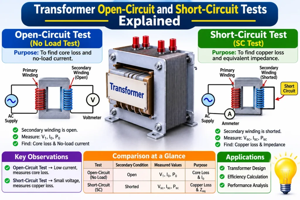

Every transformer leaves the factory with a test certificate, and two of the tests on it are the open-circuit test and the short-circuit test. Together they tell you almost everything about the transformer’s losses, its efficiency at any load and how much its voltage will drop when you load it — all without ever connecting a load.
That is the clever part. A full-load test would need a load bank the size of the transformer and would waste megawatts of energy. These two tests avoid that. One runs the transformer on no load at rated voltage, and the other runs it short-circuited at rated current. Each test isolates one loss, so the two together give you the full picture. This article explains both tests: how they are set up, what to measure, the formulas, and a worked example on a real 10 kVA transformer.
Why Test Without Loading the Transformer?
A load test sounds simple: connect the transformer to a load, run it at full load, and measure the input and output. The problem is the scale. A 100 MVA transformer at full load would need a 100 MW load bank, a substation to feed it and a way to dump the heat. That is expensive, impractical and wasteful — and it is why the industry does not do it.
The open-circuit and short-circuit tests solve the problem by splitting it in two. Each test creates only one of the two losses, so each test measures that loss directly. Add the two together and you have the total loss at any load, from which the efficiency follows. The voltage regulation follows too, from the short-circuit test data. Two small tests, run at a fraction of full power, give you the numbers a full-load test would give — and that is why they are on every transformer test certificate.
The Open-Circuit (No-Load) Test
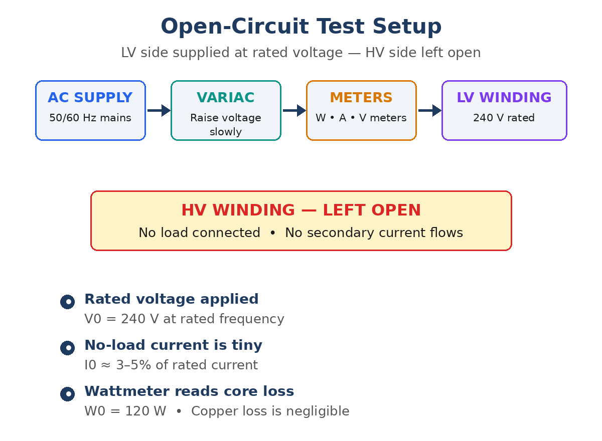
In the open-circuit test, the low-voltage winding is supplied at its rated voltage while the high-voltage winding is left open, so the transformer runs on no load. A variac adjusts the supply, and a wattmeter, voltmeter and ammeter measure the power, voltage and current. Because the secondary is open, the only current is the no-load current, which is only 3–5% of the rated current.
That small current is the key to the test. The copper loss depends on the square of the current, so at 3–5% of rated current it is only about 0.1–0.25% of the full-load copper loss — so small it can be ignored. The wattmeter reading is therefore the core loss alone: the iron loss of the transformer at rated voltage. The test is run at rated voltage and rated frequency, because the core loss depends on both.
The readings from the open-circuit test give the core loss and the no-load parameters of the transformer:
- Core loss: Pi = W0 (wattmeter reading)
- No-load power factor: cos φ0 = W0 / (V0 × I0)
- Magnetizing current: Im = I0 sin φ0
- Core-loss current: Iw = I0 cos φ0
- Shunt resistance and reactance: R0 = V0 / Iw and X0 = V0 / Im
The no-load power factor is low, typically 0.2 to 0.3, because the no-load current is mostly magnetizing current. The core loss stays constant at any load, since the supply voltage stays near rated value — that is why it is measured once and used for every load point.
The Short-Circuit Test
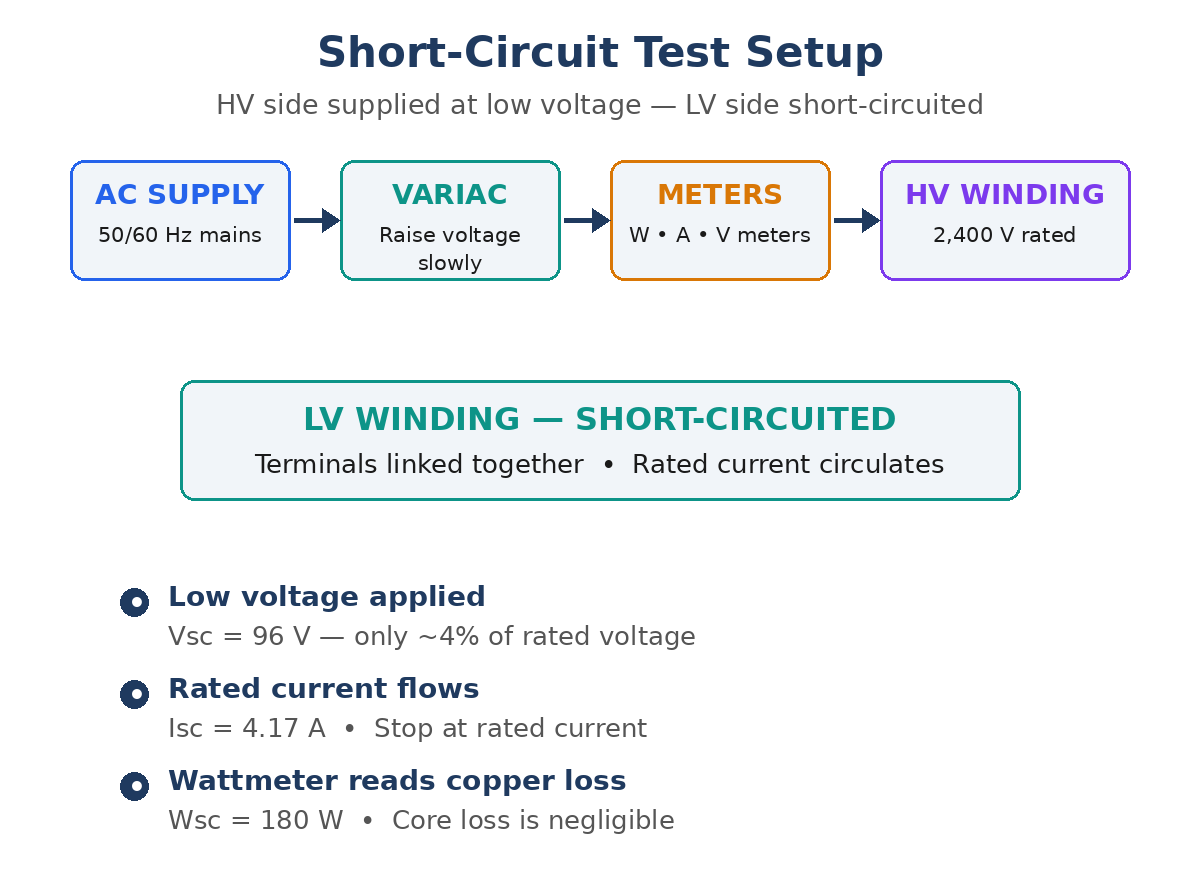
In the short-circuit test, the low-voltage winding is short-circuited and the high-voltage winding is supplied through a variac, with a wattmeter, voltmeter and ammeter measuring the input. The voltage is raised slowly from zero until the rated current flows in the windings. That takes only a small voltage — typically 4–10% of the rated voltage — because the winding impedance is low.
At that low voltage, the core flux is only 4–10% of its normal value, and the core loss depends on the square of the flux, so it is under 1% of the normal core loss — so small it can be ignored. The wattmeter reading is therefore the full-load copper loss alone. The test is run with rated current flowing, because the copper loss is measured at that current.
- Full-load copper loss: Pcu = Wsc (wattmeter reading at rated current)
- Short-circuit power factor: cos φsc = Wsc / (Vsc × Isc)
- Equivalent resistance: Req = Wsc / Isc2
- Equivalent impedance: Zeq = Vsc / Isc, and Xeq = √(Zeq2 − Req2)
The short-circuit voltage Vsc, as a percentage of the rated voltage, is the percentage impedance of the transformer — a number that appears on the nameplate and is used for fault-current and parallel-operation calculations. The resistance and reactance from this test are the same values used in the voltage regulation formula.
OC Test vs SC Test
| Feature | Open-circuit test | Short-circuit test |
|---|---|---|
| Also called | No-load test | Impedance test |
| Winding supplied | Low-voltage winding | High-voltage winding |
| Other winding | Left open | Short-circuited |
| Voltage applied | Rated voltage | 4–10% of rated voltage |
| Current drawn | 3–5% of rated current | Rated current |
| What it measures | Core loss (iron loss) | Copper loss at full load |
| What it gives | R0, X0, no-load current | Req, Xeq, % impedance |
| Instruments used | Wattmeter, voltmeter, ammeter | Wattmeter, voltmeter, ammeter |
| Power used | Small — core loss only | Small — copper loss only |
| Power factor | Very low (0.2–0.3) | Low (0.2–0.4) |
| Why it is done | Find the core loss and no-load current | Find the copper loss and impedance |
Worked Example
A 10 kVA, 2,400/240 V single-phase transformer gives these test results. Open-circuit test, LV side: V0 = 240 V, I0 = 1.5 A, W0 = 120 W. Short-circuit test, HV side: Vsc = 96 V, Isc = 4.17 A, Wsc = 180 W.
From the open-circuit test, the core loss is Pi = 120 W. The no-load power factor is cos φ0 = W0 / (V0 × I0) = 120 / (240 × 1.5) = 0.333. The core-loss current is Iw = I0 cos φ0 = 1.5 × 0.333 = 0.5 A, and the magnetizing current is Im = √(1.52 − 0.52) = 1.41 A. The shunt resistance is R0 = V0 / Iw = 240 / 0.5 = 480 Ω, and the shunt reactance is X0 = V0 / Im = 240 / 1.41 = 170 Ω.
From the short-circuit test, the full-load copper loss is Pcu = 180 W. The equivalent impedance is Zeq = Vsc / Isc = 96 / 4.17 = 23 Ω, referred to the HV side. The equivalent resistance is Req = Wsc / Isc2 = 180 / 4.172 = 10.35 Ω, and the equivalent reactance is Xeq = √(232 − 10.352) = 20.5 Ω. The percentage impedance is Vsc / Vrated = 96 / 2,400 = 4%, which is the value printed on the nameplate.
Now the efficiency. At full load and unity power factor, the output is 10,000 W. The losses are 120 W of core loss and 180 W of copper loss, a total of 300 W. The efficiency is η = output / (output + losses) = 10,000 / 10,300 = 97.1%. At 0.8 power factor the output is 8,000 W, so the efficiency is 8,000 / 8,300 = 96.4%.
At half load the output is 5,000 W at unity power factor. The core loss is still 120 W, but the copper loss falls with the square of the load: (0.5)2 × 180 = 45 W. The total loss is 165 W, and the efficiency is 5,000 / 5,165 = 96.8%. The efficiency at half load is slightly lower than at full load, because the fixed core loss is a larger share of a smaller output — but the transformer is close to its best at both points, which is the sign of a well-designed unit.
The voltage regulation at full load and 0.8 power factor lagging follows from the short-circuit data. The regulation is approximately %R cos φ + %X sin φ, where %R and %X are the percentage resistance and reactance from the short-circuit test. That is why the short-circuit test is not only a loss test — it also gives the numbers for the regulation calculation. For a full explanation of the regulation formula, see our article on voltage regulation.
Efficiency and Voltage Regulation from the Two Tests
Once the core loss and the full-load copper loss are known, the efficiency at any load and any power factor follows from one formula. The output is the load times the rating times the power factor, and the losses are the core loss plus the load squared times the full-load copper loss.
The formula is η = (x × S × cos φ) / (x × S × cos φ + Pi + x2 × Pcu), where x is the fraction of full load, S is the rating in kVA and cos φ is the power factor. At half load, x = 0.5, so the copper loss is a quarter of the full-load value, while the core loss is unchanged. That is why a transformer can be most efficient below full load — the fixed loss is spread over a smaller output, but the copper loss falls faster.
Maximum Efficiency Condition
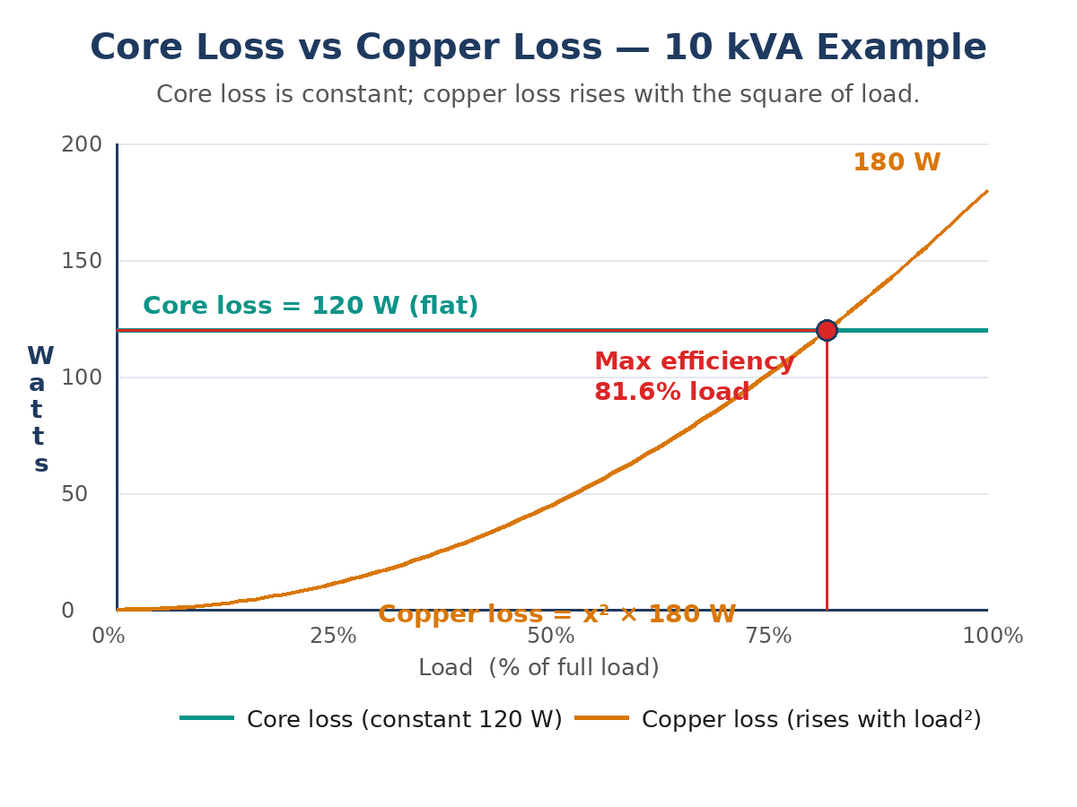
A transformer is most efficient when its copper loss equals its core loss. At that load the two losses are balanced, and the efficiency is at its peak. The load at maximum efficiency is x = √(Pi / Pcu), as a fraction of full load.
For the 10 kVA transformer in the worked example, the core loss is 120 W and the full-load copper loss is 180 W, so the load at maximum efficiency is √(120 / 180) = 0.816, or 81.6% of full load. At that load the output is 8,160 W at unity power factor, each loss is 120 W, and the efficiency is 8,160 / 8,400 = 97.1% — the highest this transformer can reach.
Common Mistakes and Safety Notes
- Testing the wrong winding: The open-circuit test is done on the low-voltage side, because that is where rated voltage is easy to reach. The short-circuit test is done on the high-voltage side, because that is where rated current is easy to reach. Swapping them makes both tests awkward and the readings wrong.
- Raising the voltage too fast in the short-circuit test: The voltage must be raised slowly from zero, watching the ammeter. A sudden jump can push the current past rated value and overheat the windings before the reading is taken.
- Forgetting to correct for temperature: The copper loss is measured at the test temperature and must be corrected to the reference temperature, usually 75 °C, before it is used in the efficiency calculation. The core loss needs no correction.
- Using the wrong frequency: Both tests must be run at the rated frequency. The core loss changes with frequency, so a 50 Hz test on a 60 Hz transformer gives the wrong core loss.
- Leaving the short circuit loose: The shorting link on the LV winding must be tight and of low resistance. A loose link adds resistance to the circuit and inflates the measured copper loss.
- Measuring with the wrong range: The wattmeter in the open-circuit test reads a small power at a low power factor, so it must be a low-power-factor wattmeter on the right range, or the reading will be unreliable.
- Treating the short-circuited transformer as safe: The LV winding is shorted, but the HV winding is live during the test, and the shorting link carries full rated current. Treat the whole unit as live until the supply is off and the windings are discharged.
- Skipping the insulation test first: Before either test, check the insulation resistance. A transformer with damaged insulation should not be energized for testing until it is dried out or repaired.
Frequently Asked Questions
What is the open-circuit test of a transformer?
The open-circuit test, also called the no-load test, supplies the low-voltage winding at rated voltage with the high-voltage winding left open. The wattmeter reading is the core loss, because the no-load current is only 3–5% of rated current and the copper loss is negligible.
What is the short-circuit test of a transformer?
The short-circuit test, also called the impedance test, short-circuits the low-voltage winding and supplies the high-voltage winding with just enough voltage — 4–10% of rated — to circulate rated current. The wattmeter reading is the full-load copper loss, because the core loss at that low voltage is negligible.
Why is the open-circuit test done on the LV side?
The open-circuit test needs rated voltage, and rated voltage is easier and safer to reach on the low-voltage side. A 240 V supply and ordinary instruments are enough, where the high-voltage side would need a kilovolt supply and high-voltage instruments.
What is the difference between core loss and copper loss?
Core loss is the iron loss in the core — hysteresis and eddy currents — and it stays constant at any load because the voltage stays near rated value. Copper loss is the I²R loss in the windings, and it rises with the square of the load current. The open-circuit test measures the first, the short-circuit test measures the second.
How do you calculate transformer efficiency from the OC and SC tests?
Efficiency = output / (output + core loss + copper loss at that load). The core loss comes from the open-circuit test and the full-load copper loss from the short-circuit test. At a load fraction x, the copper loss is x² times the full-load value, so η = (x × S × cos φ) / (x × S × cos φ + Pi + x² × Pcu).
Conclusion
The open-circuit test and the short-circuit test are the two tests that replace a full-load test. One runs the transformer at rated voltage with no load and reads off the core loss. The other runs it at rated current with a shorted secondary and reads off the copper loss. Together they give the efficiency at any load, the load for maximum efficiency and the voltage regulation — all measured with a variac, a wattmeter and a few instruments, at a fraction of full power. If you want the same tests explained with more worked examples, a good next read is this guide: Open Circuit and Short Circuit Test on Transformer on ElectronicsHub.