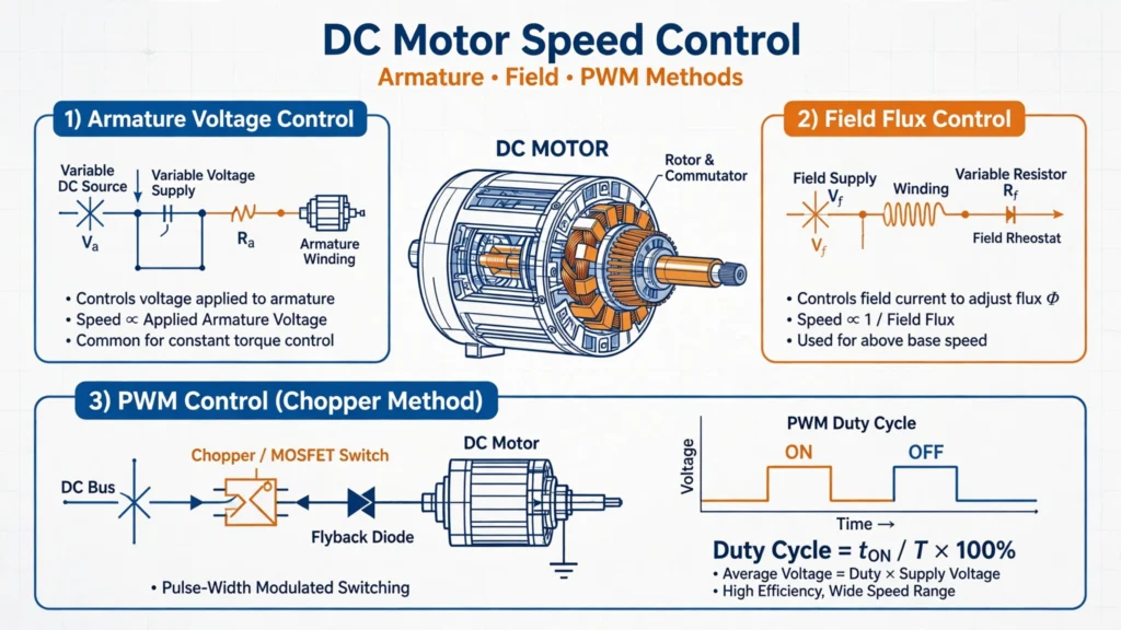

One of the oldest advantages of the DC motor is how easily its speed can be controlled. Turn a knob, change a voltage, or adjust a pulse signal, and the motor responds smoothly over a wide speed range. That is why DC motors still appear in electric vehicles, cranes, rolling mills, robotics, and precision machine tools, even though AC drives have taken over many general-purpose jobs. This guide explains the speed equation that governs every DC motor, then walks through the three classic control methods — armature voltage control, field (flux) control, and armature resistance control — plus the modern standard, PWM, and closed-loop control.
The key idea is simple: a DC motor’s speed depends on only three things — the voltage applied to the armature, the voltage lost in the armature resistance, and the strength of the magnetic field. Change any one of them and the speed changes. Each method below changes a different one, and each has its own speed range, efficiency, and trade-offs.
The DC Motor Speed Equation
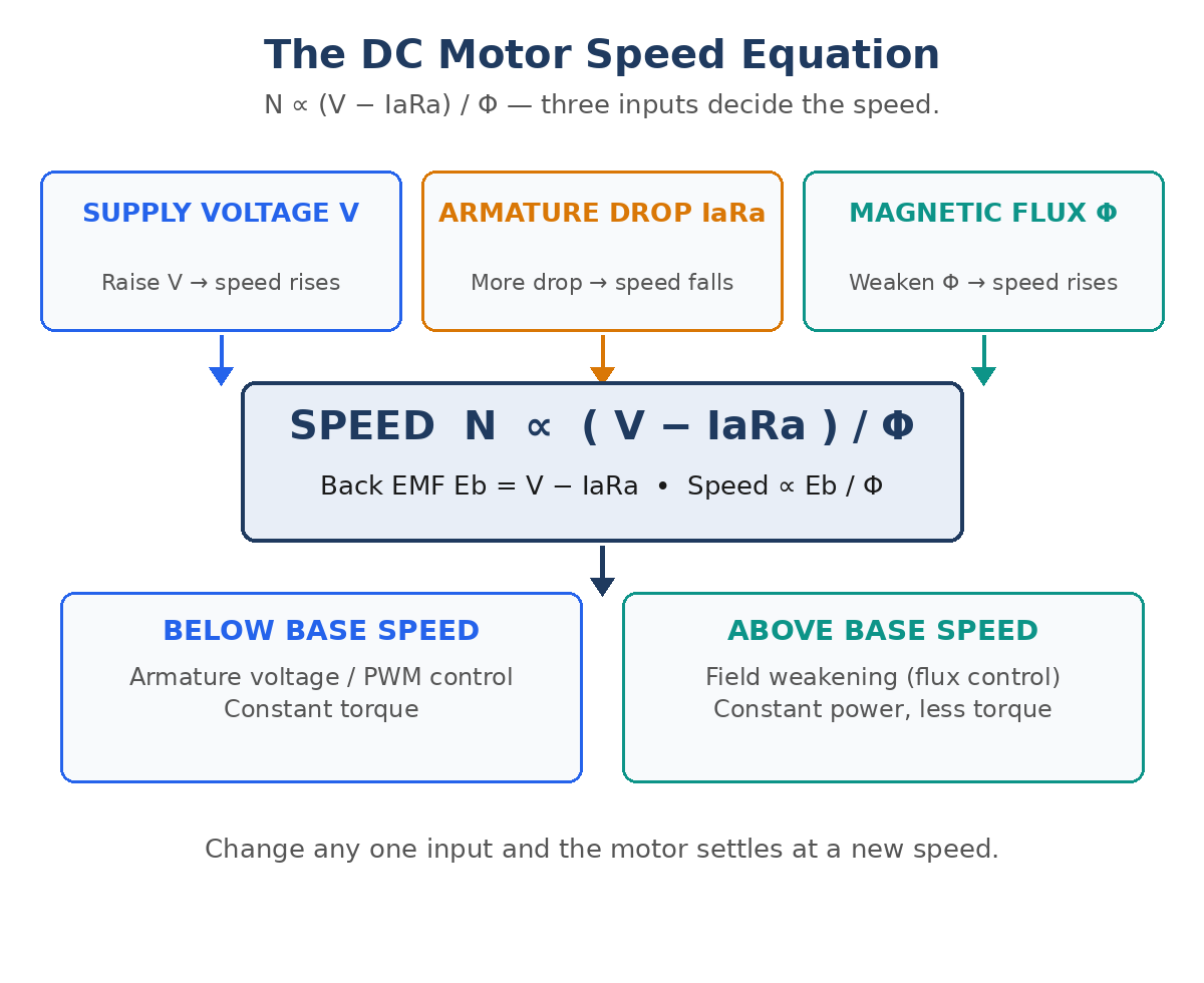
Every speed-control method follows from one equation. For a DC motor, the speed N is approximately proportional to the back EMF divided by the magnetic flux:
N ∝ (V − IaRa) / Φ
Here V is the supply voltage applied to the armature, Ia is the armature current, Ra is the armature resistance, and Φ (phi) is the magnetic flux per pole. The term (V − IaRa) is the back EMF (Eb) — the voltage the motor generates as it spins, which opposes the supply. The equation tells you there are only three levers to pull: change the armature voltage V, change the armature resistance Ra, or change the flux Φ. The DC motor guide explains back EMF and how it limits the armature current, and our article on the types of DC motor shows which of these methods suit shunt, series, and compound motors.
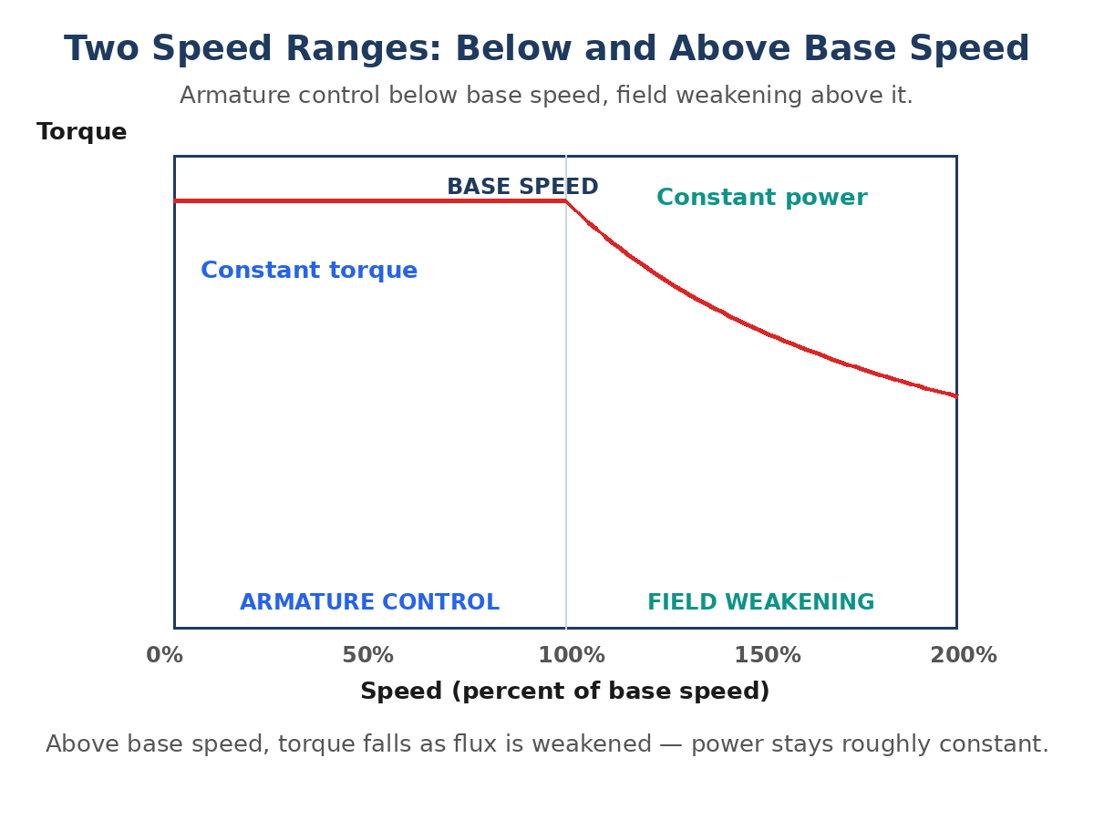
Two speed ranges matter in practice. Base speed is the speed at rated voltage and full field flux. Methods that reduce the armature voltage give speeds below base speed, with full torque available. Methods that weaken the field give speeds above base speed, but with less torque. A complete drive often combines both: armature voltage control below base speed and field weakening above it.
Method 1: Armature Voltage Control
Armature voltage control varies the voltage applied to the armature while the field flux stays constant. Because speed is roughly proportional to armature voltage, lowering the voltage lowers the speed smoothly, and raising it raises the speed — up to the rated voltage. The classic implementation is the Ward Leonard system, in which a motor-generator set supplies a variable DC voltage to the armature, but modern drives do the same job with a controlled rectifier or a DC chopper.
This is the most fundamental and widely used method because it gives smooth speed control below base speed at constant torque — the motor can deliver its full rated torque at any speed in this range, which is exactly what cranes, hoists, and machine tools need. It is efficient, because no power is deliberately wasted in a resistor, and it works on shunt and separately excited motors, where the armature and field have separate supplies. Its limit is that it cannot take the motor above base speed; for that, field weakening is needed.
Method 2: Field Control (Flux Weakening)
Field control varies the current through the field winding, which changes the magnetic flux Φ. A variable resistor (rheostat) in series with the shunt field winding reduces the field current, weakens the flux, and — since speed is inversely proportional to flux — the motor speeds up. Strengthening the field slows the motor down. This method is also called flux control.
Field control is the standard way to run a DC motor above its base speed, typically up to about twice base speed. It is cheap and simple — only a small rheostat in the low-current field circuit is needed — and it is efficient because the field circuit carries little power. But it has limits: weakening the flux also weakens the torque, so the motor delivers constant power rather than constant torque above base speed; excessive weakening distorts commutation and can cause sparking at the brushes; and it does not work on permanent-magnet motors, whose flux is fixed. The DC shunt motor is the classic machine for field control, because its field winding is separate from the armature and easy to adjust.
Method 3: Armature Resistance Control
Armature resistance control inserts a variable resistor in series with the armature. The extra resistance drops some of the supply voltage, so less voltage reaches the armature, the back EMF falls, and the motor slows down. It is the simplest method of all — just a rheostat in the armature circuit — and it works on shunt, series, and compound motors.
Its drawback is efficiency. The resistor burns the extra power as heat, so the method wastes energy and the speed regulation is poor: the speed changes with load, because the voltage drop across the resistor depends on the armature current. It is also limited to speeds below base speed. For those reasons, armature resistance control is now mostly a legacy or teaching method, used in small motors, laboratory setups, and older installations. In new designs, PWM has replaced it almost entirely.
Method 4: PWM (Pulse Width Modulation)
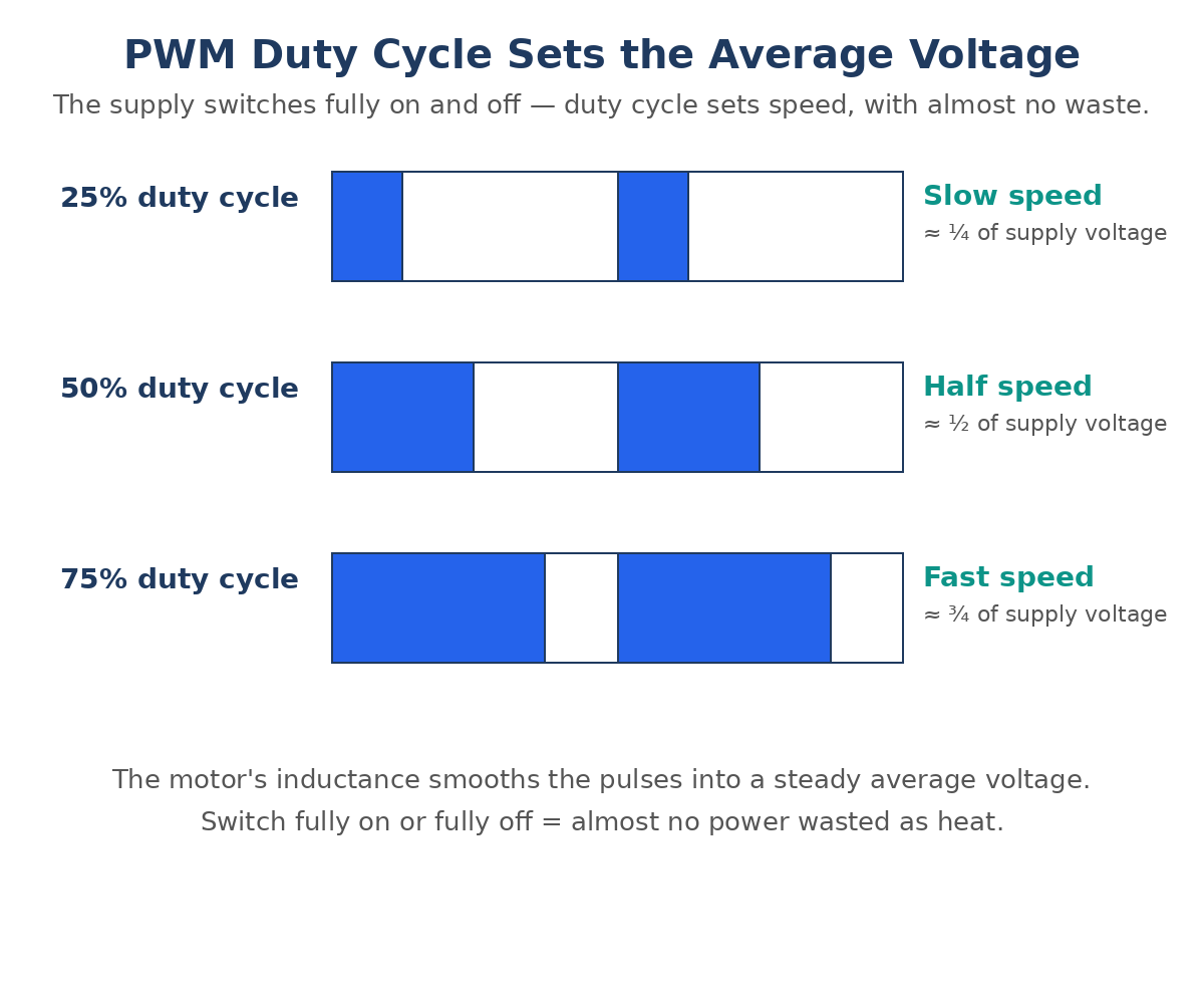
Pulse width modulation is the modern standard for DC motor speed control. Instead of reducing the voltage with a resistor, a PWM controller switches the full supply voltage on and off thousands of times per second using a power transistor such as a MOSFET or IGBT. The duty cycle — the percentage of each switching period that the power is on — sets the average voltage delivered to the motor. A 25% duty cycle delivers roughly a quarter of the supply voltage and runs the motor slowly; a 75% duty cycle runs it fast.
PWM is efficient because the switching transistor is either fully on or fully off, so it wastes almost no power as heat — unlike a resistor, which burns the difference. It gives smooth, precise speed control from near zero to full speed, works with brushed and brushless DC motors alike, and is the method used in robotics, electric vehicles, CNC machines, and small appliances. At a typical switching frequency of a few kilohertz or higher, the motor’s own inductance smooths the pulses, so the motor sees a steady average voltage. The BLDC motor article shows how PWM drives the brushless motors used in drones, fans, and EVs.
Method 5: Closed-Loop Control
All the methods above are open-loop: they set a voltage or a duty cycle and accept whatever speed results. If the load changes, the speed drifts. Closed-loop control fixes that by measuring the actual speed — with an encoder, tachogenerator, or back-EMF sensing — and feeding the error back to the controller, which adjusts the voltage or PWM duty cycle to hold the speed constant. A PID (proportional-integral-derivative) controller is the usual way to do this.
Closed-loop control is essential in servo systems, robotics, CNC machines, and any application where speed must stay constant under a changing load. It is usually combined with PWM: the PWM stage supplies the power, and the feedback loop decides the duty cycle. Modern DC drives package both together in a single controller.
Comparing the Speed Control Methods
| Method | Speed Range | Torque | Efficiency | Best For |
|---|---|---|---|---|
| Armature voltage control | Below base speed | Constant torque | High | Cranes, hoists, machine tools, rolling mills |
| Field (flux) control | Above base speed (up to ~2×) | Constant power, torque falls | High | Wide speed range, traction, spindles |
| Armature resistance control | Below base speed | Falls with speed | Low — power wasted as heat | Small motors, legacy systems, teaching |
| PWM control | Near zero to full speed | Full torque at low speed | Very high | Robotics, EVs, CNC, appliances, BLDC drives |
| Closed-loop (PID + PWM) | Full range, held constant | As commanded | Very high | Servo systems, precision positioning |
Worked Example: Speed from Armature Voltage
A worked example shows the speed equation in action. Take a DC shunt motor rated at 220 V with an armature resistance Ra of 0.5 Ω. At full load it draws an armature current Ia of 20 A, and it runs at 1,500 RPM. The back EMF is Eb = V − IaRa = 220 − (20 × 0.5) = 220 − 10 = 210 V.
Now reduce the supply voltage to 150 V, keeping the field flux and the load the same. The new back EMF is approximately 150 − 10 = 140 V (the armature drop stays about 10 V at the same current). Because speed is proportional to back EMF at constant flux, the new speed is N2 = 1,500 × (140 / 210) = 1,000 RPM. Halving the voltage roughly halves the speed — which is why armature voltage control feels so direct and predictable.
A second example shows field weakening. If the same motor’s field flux is reduced by 25% while the armature voltage stays at 220 V, the speed rises in inverse proportion: N2 = 1,500 / 0.75 = 2,000 RPM. The motor now runs above its base speed, but its torque capability falls by the same proportion, so this method suits loads that need less torque at high speed, such as a lathe spindle taking a light finishing cut.
Which Method Should You Choose?
- New design, any size: use PWM, usually with closed-loop feedback. It is efficient, precise, and cheap thanks to modern MOSFET and IGBT drives.
- Speeds above base speed: add field weakening on a shunt or separately excited motor — the only way to exceed base speed without raising the supply voltage.
- Heavy industrial drive (cranes, mills): armature voltage control with a modern thyristor or chopper drive gives smooth constant-torque control below base speed.
- Simple low-cost job: a small rheostat in the armature circuit still works for fractional-horsepower motors, but expect wasted heat and speed that drifts with load.
- Series motor (traction, hoists): note that a DC series motor’s speed is controlled mainly by armature voltage or resistance — field control is not practical because the field carries the full armature current.
Frequently Asked Questions
What is the best method to control DC motor speed?
PWM is the best method for most modern applications: it is efficient, precise, and gives smooth control from near zero to full speed. For large industrial drives, armature voltage control with a thyristor or chopper drive is the classic choice, and closed-loop feedback is added whenever speed must stay constant under changing load.
How does PWM control DC motor speed?
PWM switches the supply voltage on and off rapidly. The duty cycle — the percentage of time the power is on — sets the average voltage the motor receives. A higher duty cycle means a higher average voltage and a higher speed. Because the switch is either fully on or fully off, very little power is wasted as heat.
What is flux weakening in a DC motor?
Flux weakening reduces the field current, which weakens the magnetic flux. Because speed is inversely proportional to flux (N ∝ 1/Φ), the motor speeds up above its base speed. Torque falls in the same proportion, so the motor delivers roughly constant power in this range.
Can you control the speed of a DC motor with a resistor?
Yes — a variable resistor in series with the armature lowers the voltage reaching the motor and slows it down. But it wastes power as heat, gives poor speed regulation, and only works below base speed. PWM is the efficient modern replacement.
What is the speed equation of a DC motor?
Speed N ∝ (V − IaRa) / Φ, where V is the armature supply voltage, IaRa is the voltage drop in the armature resistance, and Φ is the magnetic flux per pole. Speed rises with voltage, falls with armature resistance drop, and rises when flux is weakened.
Conclusion
DC motor speed control comes down to one equation — N ∝ (V − IaRa) / Φ — and three levers: armature voltage, armature resistance, and field flux. Armature voltage control gives smooth constant-torque speed below base speed; field weakening extends the range above base speed at constant power; armature resistance control is simple but wasteful; and PWM, usually with closed-loop feedback, is the efficient modern standard that does the job best in almost every new design. Choose the method that matches your speed range, torque needs, and efficiency budget. For a deeper look at each technique with practical guidance, see the speed control techniques for DC motors on Electronics360.