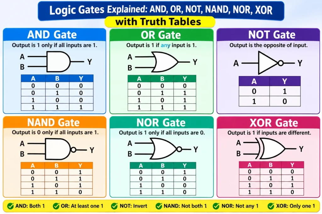

Every computer, phone, and smart appliance runs on decisions made by tiny circuits called logic gates. A logic gate takes one or more binary inputs — a 0 or a 1 — and produces a single binary output according to a fixed rule. Combine enough of these simple gates and you get everything from a pocket calculator to a supercomputer. If you want to understand digital electronics, logic gates are where it starts.
This guide explains the seven logic gates — AND, OR, NOT, NAND, NOR, XOR, and XNOR — with a truth table for each one, the Boolean expression, the standard IC number, and real examples of where each gate is used. No prior knowledge of digital electronics is needed: if you know that 1 means ON and 0 means OFF, you are ready.
What Is a Logic Gate?
A logic gate is a small electronic circuit that performs a logical operation on binary signals. Its inputs and output can only be in one of two states: logic 0 (LOW) or logic 1 (HIGH). In a real circuit, these states are voltages. In the classic TTL (transistor-transistor logic) family, 0 V to 0.8 V counts as LOW and 2 V to 5 V counts as HIGH, on a 5 V supply. In modern CMOS circuits running at 3.3 V, the thresholds are roughly one-third and two-thirds of the supply voltage. The exact voltages depend on the logic family, but the logic itself is the same everywhere.
Logic gates are built from transistors. A single gate may contain just a handful of transistors, while a modern microprocessor contains billions of them arranged into gates, flip-flops, and memory cells. Our guide to what a transistor is explains the switching device inside every gate, and our semiconductor guide covers the materials they are made from.
How to Read a Truth Table
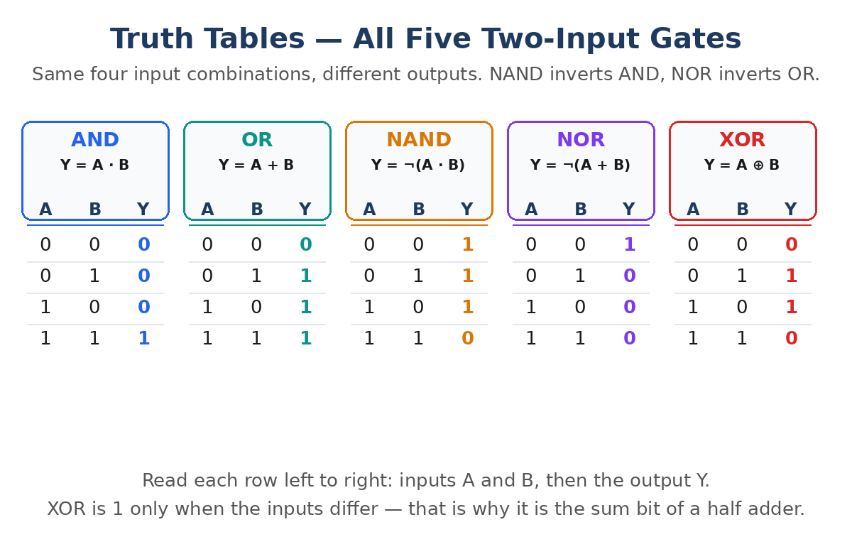
A truth table lists every possible combination of inputs and the output each combination produces. It is the standard way to describe a gate, and it is the fastest way to learn one. A gate with two inputs (A and B) has four possible combinations, because each input can be 0 or 1: 00, 01, 10, and 11. A gate with n inputs has 2n rows — three inputs give eight combinations and four inputs give sixteen.
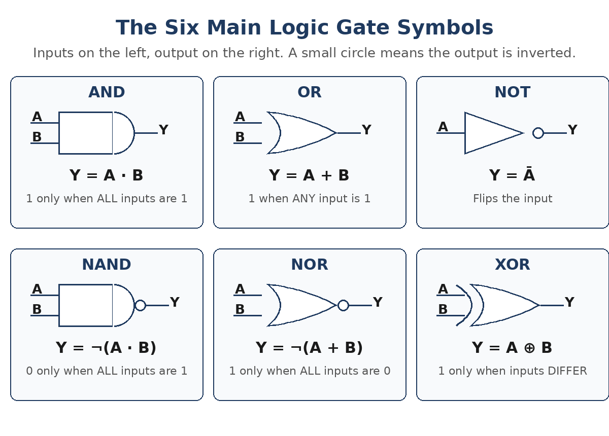
Read a truth table row by row, left to right: the first columns are the inputs, the last column is the output. In the tables below, A and B are the inputs and Y is the output. The Boolean expression beside each table is the same rule written in algebra: the dot (·) means AND, the plus (+) means OR, and a bar over a letter (Ā) means NOT.
The Seven Logic Gates at a Glance
There are three basic gates — AND, OR, and NOT — and four gates built by combining them: NAND, NOR, XOR, and XNOR. The table below summarizes all seven before we look at each one in detail.
| Gate | Boolean Expression | Output Is 1 When | Inputs | Universal Gate |
|---|---|---|---|---|
| AND | Y = A · B | All inputs are 1 | 2 or more | No |
| OR | Y = A + B | At least one input is 1 | 2 or more | No |
| NOT | Y = Ā | The input is 0 | 1 | No |
| NAND | Y = ¬(A · B) | Not all inputs are 1 | 2 or more | Yes |
| NOR | Y = ¬(A + B) | All inputs are 0 | 2 or more | Yes |
| XOR | Y = A ⊕ B | Inputs are different | 2 | No |
| XNOR | Y = ¬(A ⊕ B) | Inputs are the same | 2 | No |
AND Gate
The AND gate gives an output of 1 only when all of its inputs are 1. If even one input is 0, the output is 0. It performs logical multiplication, which is why its Boolean expression is written Y = A · B. Think of two switches wired in series: the light turns on only when both switches are closed.
| A | B | Y = A · B |
|---|---|---|
| 0 | 0 | 0 |
| 0 | 1 | 0 |
| 1 | 0 | 0 |
| 1 | 1 | 1 |
AND gates are used as enable gates: a signal passes through only when the enable input is HIGH. A common example is a safety interlock — a machine starts only when the guard door is closed and the start button is pressed. The standard TTL chip is the 7408, which contains four 2-input AND gates in one 14-pin package.
OR Gate
The OR gate gives an output of 1 when any of its inputs is 1. The output is 0 only when all inputs are 0. It performs logical addition, written Y = A + B. Think of two switches wired in parallel: the light turns on if either switch — or both — is closed.
| A | B | Y = A + B |
|---|---|---|
| 0 | 0 | 0 |
| 0 | 1 | 1 |
| 1 | 0 | 1 |
| 1 | 1 | 1 |
OR gates are the natural choice for alarm systems. In a room with two windows and a door, each fitted with a sensor that outputs HIGH when opened, an OR gate raises the alarm if any one of them is opened. The standard TTL chip is the 7432, a quad 2-input OR gate.
NOT Gate
The NOT gate, also called an inverter, has a single input and a single output. It simply flips the input: a 1 in gives a 0 out, and a 0 in gives a 1 out. Its Boolean expression is Y = Ā, read as “Y equals NOT A”. The NOT gate symbol is a triangle with a small circle (the inversion bubble) at the output.
| A | Y = Ā |
|---|---|
| 0 | 1 |
| 1 | 0 |
Inverters are used everywhere a signal must be reversed — for example, to drive an active-low enable pin, or to make a simple oscillator by chaining an odd number of inverters in a loop. The standard TTL chip is the 7404, which packs six inverters into one package. Our diode guide explains the other basic semiconductor building block that often appears alongside gates in digital circuits.
NAND Gate
NAND stands for NOT-AND. It is an AND gate followed by a NOT gate, so its output is the opposite of AND: the output is 0 only when all inputs are 1, and 1 in every other case. Its Boolean expression is Y = ¬(A · B).
| A | B | Y = ¬(A · B) |
|---|---|---|
| 0 | 0 | 1 |
| 0 | 1 | 1 |
| 1 | 0 | 1 |
| 1 | 1 | 0 |
NAND is called a universal gate because any other logic function — AND, OR, NOT, XOR, and more — can be built using only NAND gates. That is why NAND is the workhorse of digital design: manufacturers can standardize on one gate type and build everything from it. The standard TTL chip is the 7400, a quad 2-input NAND gate and one of the most famous ICs ever made.
NOR Gate
NOR stands for NOT-OR. It is an OR gate followed by a NOT gate, so its output is 1 only when all inputs are 0. If any input is 1, the output is 0. Its Boolean expression is Y = ¬(A + B).
| A | B | Y = ¬(A + B) |
|---|---|---|
| 0 | 0 | 1 |
| 0 | 1 | 0 |
| 1 | 0 | 0 |
| 1 | 1 | 0 |
NOR is the other universal gate: like NAND, it can build any logic function on its own. NOR gates are useful as “no condition active” detectors — the output is HIGH only when nothing is happening. A classic example is a landing-gear warning circuit that stays quiet only when every gear sensor reports “down and locked”. The standard TTL chip is the 7402, a quad 2-input NOR gate.
XOR Gate
XOR stands for exclusive OR. Its output is 1 only when the two inputs are different — one is 0 and the other is 1. If both inputs are the same, the output is 0. Its Boolean expression is Y = A ⊕ B, where ⊕ is the exclusive-OR symbol.
| A | B | Y = A ⊕ B |
|---|---|---|
| 0 | 0 | 0 |
| 0 | 1 | 1 |
| 1 | 0 | 1 |
| 1 | 1 | 0 |
XOR gates are the heart of binary addition: in a half adder, the XOR gate produces the sum bit. They are also used as controlled inverters and in parity checkers, where they detect whether the number of 1s in a data word is odd or even. The standard TTL chip is the 7486, a quad 2-input XOR gate.
XNOR Gate
XNOR is the complement of XOR: its output is 1 only when the two inputs are the same — both 0 or both 1. It works as an equality detector, which makes it useful in comparators that check whether two binary numbers match. Its Boolean expression is Y = ¬(A ⊕ B).
| A | B | Y = ¬(A ⊕ B) |
|---|---|---|
| 0 | 0 | 1 |
| 0 | 1 | 0 |
| 1 | 0 | 0 |
| 1 | 1 | 1 |
XNOR is used less often than the other six gates, but it appears in digital comparators and in error-detection circuits. The common TTL part is the 74266, a quad 2-input XNOR gate with open-collector outputs.
Universal Gates: Building Any Logic from NAND or NOR
The most important practical fact about NAND and NOR is that either one alone can build every other gate. A NOT gate is a NAND gate with its two inputs tied together. An AND gate is a NAND gate followed by another NAND gate wired as an inverter. An OR gate can be built from three NAND gates by inverting each input first and then NANDing the results. This property is called functional completeness.
In real chip manufacturing this matters enormously. Instead of fabricating seven different gate types, a factory can build one NAND structure billions of times and wire it into any function. That is one reason NAND gates dominate the inside of processors and memory chips — even the flash memory in a USB drive is built from NAND cells.
Logic Gate ICs: TTL vs CMOS
For learning and hobby projects, logic gates come as ready-made ICs in two classic families. The 7400 series is TTL: it runs on a fixed 5 V supply, switches fast, and uses more power. The 4000 series is CMOS: it runs on 3 V to 15 V, uses almost no power when idle, and is more sensitive to static electricity. Modern 74HC and 74HCT parts combine CMOS power consumption with TTL-compatible 5 V operation.
| Gate | 7400 Series (TTL) | 4000 Series (CMOS) | Supply Voltage |
|---|---|---|---|
| AND | 7408 | 4081 | TTL 5 V; CMOS 3–15 V |
| OR | 7432 | 4071 | TTL 5 V; CMOS 3–15 V |
| NOT | 7404 | 4049 | TTL 5 V; CMOS 3–15 V |
| NAND | 7400 | 4011 | TTL 5 V; CMOS 3–15 V |
| NOR | 7402 | 4001 | TTL 5 V; CMOS 3–15 V |
| XOR | 7486 | 4070 | TTL 5 V; CMOS 3–15 V |
For a first breadboard project, the 74HC series is the safest choice: it works with 5 V Arduino-style logic, draws little current, and the pinouts match the classic 7400 numbers (a 74HC08 is a quad AND gate, just like the 7408). Always check the datasheet for the exact part before wiring power — a TTL chip fed 12 V will be destroyed instantly.
Worked Example: The Half Adder
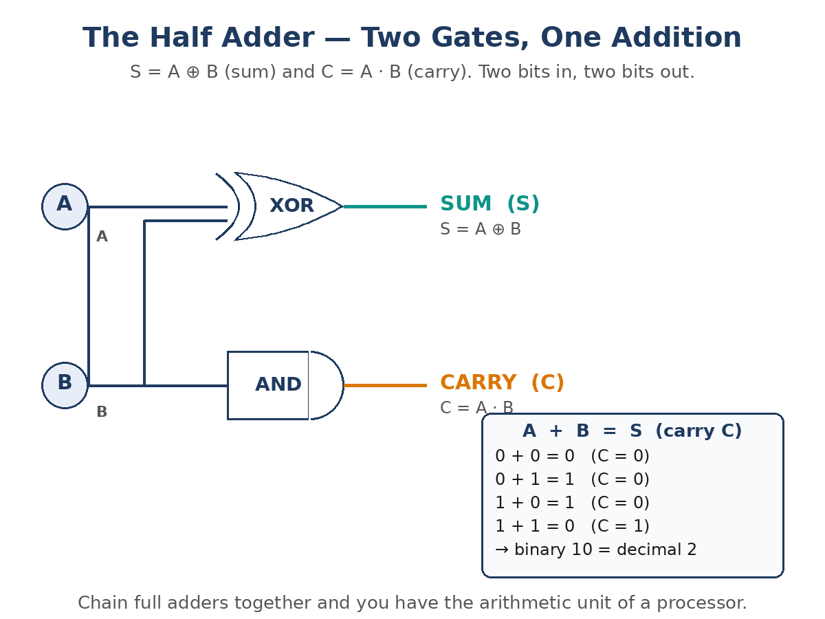
The half adder is the simplest arithmetic circuit, and it shows why logic gates matter. It adds two single bits, A and B, and produces a sum (S) and a carry (C). The sum is the XOR of the inputs, and the carry is the AND of the inputs: S = A ⊕ B and C = A · B.
Work through the four cases: 0 + 0 gives sum 0 and carry 0. 0 + 1 gives sum 1 and carry 0. 1 + 0 gives sum 1 and carry 0. 1 + 1 gives sum 0 and carry 1 — that is binary 10, which is decimal 2. Two gates, one addition. Chain many full adders together and you have the arithmetic unit of a processor.
Where Logic Gates Are Used
Logic gates are the atoms of digital electronics, so their applications are almost endless:
- Computers and phones: processors, memory, and controllers are built entirely from gates, mostly NAND structures.
- Arithmetic circuits: adders, subtractors, and comparators are built from XOR, AND, and OR gates.
- Control systems: PLCs implement AND, OR, and NOT logic in ladder logic to run factories and machines. Our PLC guide explains how industrial controllers use the same logic at a larger scale.
- Safety interlocks: AND gates make sure all conditions are met before a machine starts; OR gates raise an alarm if any sensor trips.
- Data handling: multiplexers, decoders, and parity checkers route and verify digital data using gates.
- Everyday electronics: washing machines, traffic lights, calculators, and remote controls all contain gate-based logic.
Frequently Asked Questions
How many logic gates are there?
There are seven standard logic gates: AND, OR, NOT, NAND, NOR, XOR, and XNOR. The first three are the basic gates, and the other four are built by combining them. NAND and NOR are called universal gates because either one can build all the others.
What is the difference between NAND and AND gates?
A NAND gate is an AND gate with its output inverted. The AND gate outputs 1 only when all inputs are 1; the NAND gate outputs 0 in that case and 1 in every other case. NAND is a universal gate, while AND is not.
What does 1 and 0 mean in a logic gate?
1 means HIGH (ON) and 0 means LOW (OFF). In a real circuit these are voltages: in TTL logic, roughly 0 V is LOW and 5 V is HIGH; in 3.3 V CMOS logic, roughly 0 V is LOW and 3.3 V is HIGH. The logic is the same regardless of the voltage levels.
Which logic gate is used in a half adder?
A half adder uses one XOR gate for the sum and one AND gate for the carry: S = A ⊕ B and C = A · B. It adds two single bits, producing a sum bit and a carry bit.
What is the 7400 series?
The 7400 series is a family of TTL logic ICs, each containing several gates in one chip — for example, the 7400 is a quad NAND gate, the 7408 is a quad AND gate, and the 7432 is a quad OR gate. The 4000 series is the CMOS equivalent. Modern 74HC parts combine CMOS efficiency with 5 V TTL-compatible operation.
Conclusion
Logic gates are simple rules made into circuits: AND needs all inputs HIGH, OR needs any input HIGH, NOT flips its input, NAND and NOR invert those results, XOR fires when the inputs differ, and XNOR fires when they match. NAND and NOR are universal, so any digital function can be built from either one alone. From a two-gate half adder to a processor with billions of gates, everything in digital electronics is these seven rules, repeated at scale. For more truth tables, circuit diagrams, and classroom projects using these gates, see Digital Logic Gates Explained: Truth Tables, Circuits and Classroom Projects on Wiltronics.