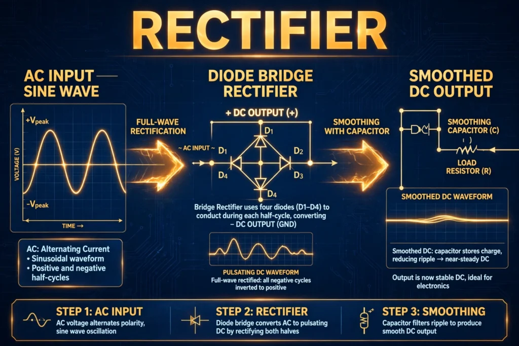

Almost every electronic device you own runs on direct current — your phone charger, laptop, LED lights, and TV all need smooth DC. Yet the electricity arriving at your wall socket is alternating current, reversing direction fifty or sixty times every second. Something has to perform that translation from AC to DC, and that something is the rectifier. It is one of the most common circuits in all of electrical engineering, hiding inside every power adapter and industrial drive you have ever used.
Despite its ubiquity, the rectifier is often treated as a black box. How does it actually turn alternating current into direct current? Why do some designs use one diode while others use four? What is the difference between half-wave, full-wave, and bridge rectifiers — and what is that leftover “ripple” everyone talks about? This guide explains what a rectifier is, how each major type works, and where rectifiers show up in the real world.
What Is a Rectifier?
A rectifier is an electronic circuit that converts alternating current (AC) into direct current (DC). It does this using diodes — semiconductor devices that conduct current in only one direction. By cleverly arranging diodes, a rectifier forces the alternating halves of the AC waveform to flow in a single direction through the load, producing a pulsating DC output.
The key idea is simple: a diode is a one-way valve for electric current. During the positive half-cycle of the AC input, the diode conducts; during the negative half-cycle, it blocks. What comes out the other side is current that always flows the same way — direct current, albeit a bumpy, pulsating version that usually needs further smoothing before it can power sensitive electronics.
Rectifiers range from a single diode in the cheapest wall adapter to massive thyristor assemblies in high-voltage DC transmission stations. But nearly all of them are variations on three basic circuits: the half-wave rectifier, the full-wave (center-tapped) rectifier, and the bridge rectifier.
How Does a Rectifier Work? (Working Principle)
The Half-Wave Rectifier
The simplest rectifier uses just one diode in series with the load. Here is what happens across one AC cycle:
- Positive half-cycle: the AC voltage forward-biases the diode, it conducts, and current flows through the load. The output follows the input’s positive hump.
- Negative half-cycle: the diode is reverse-biased and blocks completely. No current flows; the output sits at zero.
The result is a pulsating DC waveform with gaps — only half of the input power is used, and the output has a large ripple at the supply frequency (50 or 60 Hz). Half-wave rectifiers are cheap and simple, but inefficient and rough. You will find them only in undemanding applications like simple LED indicators or basic chargers where cost matters more than quality.
The Full-Wave Center-Tapped Rectifier
This design uses a center-tapped transformer secondary and two diodes. The center tap becomes the circuit’s reference point, and each diode handles one half of the secondary:
- Positive half-cycle: the upper half of the secondary forward-biases diode D1, which conducts through the load.
- Negative half-cycle: the lower half forward-biases diode D2, which conducts through the load in the same direction.
Now both halves of the AC cycle deliver power to the load — the output pulses twice per cycle (100 or 120 Hz), ripple is smaller, and transformer utilization improves. The price: you need a special center-tapped transformer, and each diode must withstand twice the peak voltage.
The Bridge Rectifier
The bridge rectifier is the most popular design, using four diodes arranged in a diamond (bridge) configuration with an ordinary, non-tapped transformer:
- Positive half-cycle: two diagonally opposite diodes conduct, routing current through the load in the forward direction.
- Negative half-cycle: the other diagonal pair conducts, routing current through the load in the same forward direction.
Like the center-tapped design, the bridge uses both half-cycles and doubles the ripple frequency, but it needs no special transformer and uses it more efficiently. The trade-off is a slightly higher voltage drop (two diode drops instead of one, roughly 1.4 V with silicon diodes). Bridge rectifier modules — four diodes in a single package — are among the most-sold components in electronics.
Smoothing the Output: Filters and Ripple
The raw output of any rectifier is pulsating DC, not the steady DC that electronics need. The pulsation is called ripple. The standard fix is a large reservoir capacitor across the output: it charges up to the peak voltage during each pulse and discharges slowly into the load between pulses, dramatically flattening the waveform. Larger capacitance (or a following voltage regulator) means smaller ripple. Ripple is usually specified as a percentage or as peak-to-peak volts, and reducing it is a central goal of power-supply design.
Types of Rectifiers
1. Half-Wave Rectifier
One diode, simplest and cheapest. Uses only half the input cycle; high ripple, poor efficiency (~40%). Suitable only for low-power, non-critical loads.
2. Full-Wave Center-Tapped Rectifier
Two diodes plus a center-tapped transformer. Uses both half-cycles; moderate ripple at twice the line frequency. Less common today because the special transformer costs more than two extra diodes.
3. Bridge Rectifier
Four diodes in a bridge; works with a standard transformer. Best transformer utilization, moderate ripple, the default choice for most single-phase DC supplies from a few watts to several kilowatts.
4. Controlled Rectifier (SCR / Thyristor Rectifier)
Replaces diodes with thyristors (SCRs), whose turn-on moment can be delayed by a gate signal. By controlling the firing angle, the output DC voltage becomes adjustable — the foundation of controlled DC drives, battery chargers with regulation, and industrial process power. This is where rectifiers graduate from fixed power supplies to true power control.
5. Three-Phase Bridge Rectifier
Six diodes (or thyristors) rectifying a three-phase supply. The output pulses six times per cycle, so ripple is inherently tiny even before filtering. This is the standard front end for industrial equipment — including the DC bus inside every variable frequency drive, which first rectifies the mains to DC and then inverts it back to variable-frequency AC for the motor.
Quick Comparison
| Feature | Half-Wave | Full-Wave Center-Tapped | Bridge |
|---|---|---|---|
| Diodes | 1 | 2 | 4 |
| Transformer | Standard | Center-tapped | Standard |
| Ripple frequency | f (50/60 Hz) | 2f (100/120 Hz) | 2f (100/120 Hz) |
| Efficiency | Low (~40%) | Good (~81%) | Good (~81%) |
| Diode voltage stress | Peak | 2x peak | Peak |
| Typical use | Simple, cheap circuits | Legacy designs | Most DC supplies |
Applications of Rectifiers
DC Power Supplies
Every regulated bench supply, wall adapter, and internal computer PSU starts with a rectifier stage (usually a bridge) followed by filtering and regulation. It is the gateway between the AC mains and the DC world of electronics.
Battery Chargers
Charging a battery fundamentally requires DC, so chargers from phone adapters to industrial forklift chargers all contain rectifiers — often controlled (thyristor) types where the charging voltage must be precisely regulated.
Variable Frequency Drives (VFDs)
A VFD’s first stage is a three-phase rectifier that creates the internal DC bus; the inverter stage then rebuilds AC at whatever frequency the motor needs. Understanding the rectifier stage explains both how VFDs work and why they can inject harmonics back into the supply. Our guide to the variable frequency drive walks through the complete rectifier–DC bus–inverter chain.
Electroplating, Welding, and Industrial Processes
Electroplating baths, anodizing lines, and DC arc welders need high-current DC — delivered by heavy-duty rectifier assemblies, sometimes rated for thousands of amperes.
HVDC Transmission
At the extreme end, thyristor and IGBT-based converter stations rectify gigawatts of AC for efficient long-distance high-voltage DC transmission, then invert it back to AC at the receiving end.
A Note on Power Quality
One side effect worth knowing: rectifier loads draw current in short pulses rather than smooth sine waves, making them non-linear loads. These pulsed currents contain harmonics that can distort the supply voltage and depress the displacement power factor of an installation — which is why large rectifier installations often include harmonic filters or power-factor correction.
Rectifier vs Inverter: Don’t Confuse Them
The names describe opposite jobs, and beginners mix them up constantly:
- Rectifier: AC to DC (diodes block the reverse half-cycles).
- Inverter: DC to AC (switches chop DC into an alternating waveform).
A solar inverter, for example, takes the DC from solar panels and inverts it into grid-compatible AC — the mirror image of what a rectifier does. Many systems, like VFDs and UPS units, contain both: a rectifier stage followed by an inverter stage.
FAQs
Why does a bridge rectifier use four diodes instead of two?
Because with a standard (non-tapped) transformer, you need two diodes conducting on each half-cycle — one to steer the incoming current and one to complete the return path — while keeping the load current flowing in the same direction. The four-diode diamond routes both half-cycles correctly without requiring a center-tapped transformer.
Which is better: bridge rectifier or center-tapped full-wave?
For new designs, the bridge rectifier almost always wins: it works with a cheaper standard transformer, uses the transformer winding more efficiently, and puts less voltage stress on each diode. The center-tapped version survives mainly in legacy equipment and textbooks.
What is ripple, and how do you reduce it?
Ripple is the residual AC pulsation riding on a rectifier’s DC output. You reduce it by increasing the filter capacitance, using full-wave or three-phase rectification (higher ripple frequency is easier to filter), adding LC or pi filters, or following the rectifier with a voltage regulator.
Can a rectifier produce pure, smooth DC?
Not by itself — a bare rectifier always outputs pulsating DC. Smooth DC requires filtering (capacitors, inductors) and usually a voltage regulator stage afterward. The rectifier is only the first step of a complete DC power supply.
What is the difference between a rectifier and a regulator?
The rectifier converts AC to (pulsating) DC; the regulator takes that rough DC and holds it at a precise, stable voltage regardless of load or input variations. A phone charger contains both: a bridge rectifier up front and a switching regulator behind it.
What happens if one diode fails in a bridge rectifier?
Typically the bridge degrades into half-wave-like operation (or shorts the transformer secondary, blowing a fuse). Symptoms include much higher ripple, overheating, and low output voltage — a common failure mode worth checking when a power supply misbehaves.
Conclusion
The rectifier is the indispensable bridge between the AC power grid and the DC-powered electronics that fill our lives. Its working principle is elegant — diodes acting as one-way valves to fold both halves of the AC cycle into a single direction — and its three classic forms (half-wave, center-tapped full-wave, and bridge) cover everything from penny-cheap indicators to multi-megawatt industrial converters. Add filtering to tame the ripple, and for adjustable output, graduate to thyristor-controlled designs. Next time you plug in a charger or watch a VFD ramp up a motor, remember: the first thing the mains meets inside is almost always a rectifier.