
If you have ever looked inside a modern motor drive, a solar inverter, or an electric vehicle charger, you have seen large power transistors bolted to heavy aluminum heatsinks. In most of those machines, the switching device doing the heavy lifting is the IGBT — the insulated gate bipolar transistor. It is the workhorse of modern power electronics, quietly controlling kilowatts of power in everything from factory automation to high-speed trains.
The IGBT earned this role because it combines the best traits of two older devices: the easy voltage-controlled gate of a MOSFET and the high current-handling ability of a bipolar junction transistor. Understanding it gives you the key to almost every modern power converter, including the variable frequency drive that controls industrial motors.
What Is an IGBT?
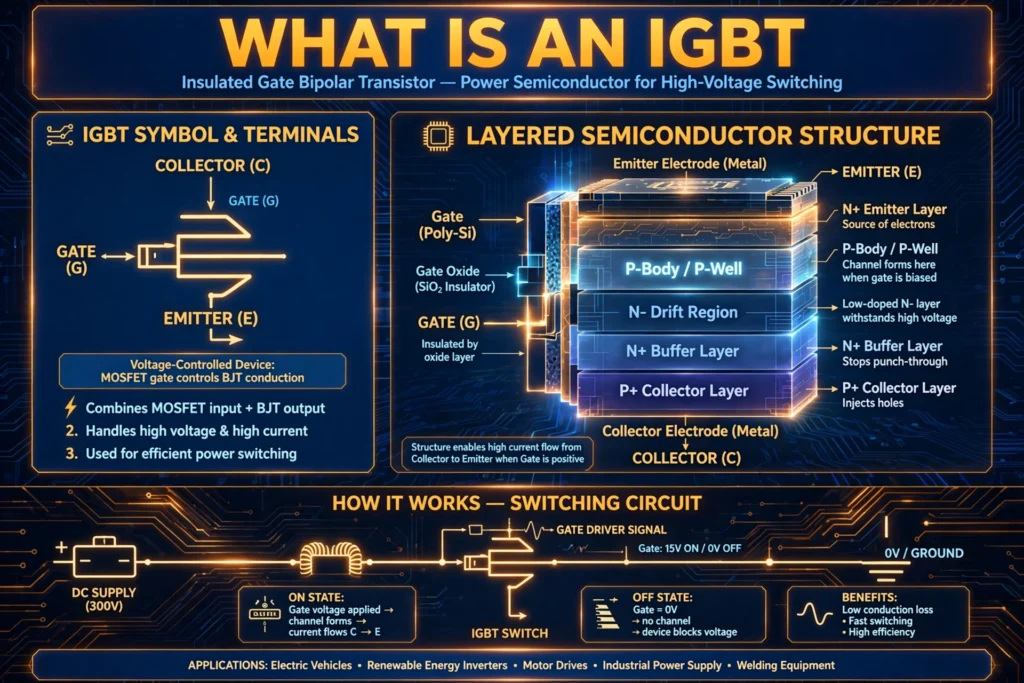
An IGBT (insulated gate bipolar transistor) is a three-terminal power semiconductor device used as an electronic switch. It is designed to switch large voltages and currents — typically hundreds of volts and tens to hundreds of amperes — while being controlled by a small voltage signal at its gate.
The name tells you how it is built. “Insulated gate” means the control terminal (the gate) is electrically isolated from the rest of the device by a thin layer of silicon dioxide, exactly like a MOSFET. This gives the IGBT a very high input impedance, so the control circuit needs almost no current to drive it. “Bipolar transistor” refers to the way current actually flows through the device: like a BJT, conduction involves both electrons and holes, which keeps the on-state voltage drop low even at high currents.
The three terminals are:
- Gate (G) — the control terminal. A voltage applied here (typically +15 V to turn on, 0 V or a small negative voltage to turn off) switches the device.
- Collector (C) — the terminal through which the main current enters.
- Emitter (E) — the terminal through which the main current exits.
In a circuit symbol, the IGBT looks like a MOSFET with an extra arrow on the collector side, reflecting its bipolar nature. Most IGBTs also include a freewheeling (anti-parallel) diode in the same package, because the inductive loads they switch — motors, transformers, coils — generate voltage spikes when current is interrupted.
IGBTs are manufactured in several package styles. Small devices come in TO-247 plastic packages you can hold between two fingers. Industrial modules are brick-sized blocks containing two, four, or six IGBTs with their diodes, rated for hundreds of amperes. These modules bolt directly onto heatsinks in drives and inverters.
How Does an IGBT Work? (Working Principle)
To understand IGBT operation, it helps to think of it as a switch with two states: ON and OFF, controlled by the gate voltage.
Turn-on: When the gate-to-emitter voltage rises above the threshold (usually around 5–7 V, with +15 V used in practice), an inversion layer forms under the gate oxide — the same MOSFET action. This opens a channel that allows current to flow into the base of an internal PNP transistor structure. The PNP transistor then turns on, injecting holes into the drift region. This flood of both electrons and holes — called conductivity modulation — dramatically lowers the resistance of the drift region, so the device conducts large currents with a small voltage drop (typically 1.5–3 V, called Vce(sat), the collector-emitter saturation voltage).
Turn-off: When the gate voltage is removed (brought to 0 V or slightly negative, often −5 to −8 V for fast, reliable switching), the MOSFET channel closes. The electron supply stops, and the stored charge in the drift region must recombine before the device fully blocks voltage. This recombination takes a short time, producing a characteristic “current tail” during turn-off. The tail is the main source of switching loss in IGBTs and is the reason IGBTs switch more slowly than pure MOSFETs.
Blocking state: With the gate off, the IGBT blocks the full DC bus voltage (600 V, 1200 V, or even 1700 V and above in high-power modules) with only tiny leakage current, thanks to its thick, lightly doped drift region.
A useful mental model: the IGBT is a MOSFET driving a wide-base BJT. The MOSFET part gives easy voltage control; the BJT part gives low on-state loss at high current. The price paid is slower switching than a MOSFET, because the BJT’s stored charge cannot vanish instantly.
Gate driver requirements: Because the gate is capacitive, the driver must briefly supply a pulse of current to charge and discharge it quickly. A typical gate driver delivers +15 V / −8 V with several amperes of peak current; selecting the right gate resistance balances switching speed against electromagnetic interference.
IGBT Characteristics
The datasheet parameters that matter most when selecting an IGBT:
- Collector-emitter voltage (Vces): the maximum voltage the device blocks when off. Common ratings: 600 V, 650 V, 1200 V, 1700 V.
- Collector current (Ic): the maximum continuous current. Ranges from a few amperes (discrete packages) to over 1000 A (large modules).
- Saturation voltage (Vce(sat)): the on-state voltage drop at rated current — lower means lower conduction loss. Typically 1.5–2.5 V for modern devices.
- Switching speed / total switching energy (Eon + Eoff): determines switching losses at a given frequency. Standard IGBTs suit 2–20 kHz; fast variants reach 50–100 kHz.
- Short-circuit withstand time: usually rated for 10 µs — the device must survive a short circuit that long so protection (like a fast MCB or desaturation detection) can react.
- Gate threshold voltage (Vge(th)): typically 5–7 V.
There is a fundamental trade-off in IGBT design: lowering Vce(sat) usually increases switching loss, and vice versa. Manufacturers offer families optimized for different points on this curve — “low saturation” types for low-frequency, high-current use and “fast switching” types for higher frequencies.
Types of IGBTs
By structure:
- Punch-through (PT) IGBTs — the older design with an N+ buffer layer; lower switching loss but limited voltage rating.
- Non-punch-through (NPT) IGBTs — simpler structure, more rugged, better short-circuit capability.
- Field-stop (FS) IGBTs — the modern standard: a thin field-stop layer lets the drift region be thinner, giving low Vce(sat) AND fast switching. Most IGBTs sold today are field-stop types.
- Reverse-conducting IGBTs (RC-IGBTs) — integrate the freewheeling diode into the same silicon chip, shrinking module size for applications like induction heating and some drives.
By package:
- Discrete IGBTs (TO-247, TO-220) — up to ~100 A, for small drives, welders, and power supplies.
- IGBT modules — half-bridge, six-pack (three-phase bridge), chopper, and PIM (power integrated module: rectifier + brake + inverter in one package) configurations for industrial drives, VFDs, and renewable energy inverters.
Related devices worth knowing: the SiC MOSFET is the IGBT’s main rival in new designs — faster switching but higher cost. Above ~3.3 kV, thyristors and IGCTs still dominate.
Applications of IGBTs
IGBTs dominate every application where medium-to-high power must be switched at moderate frequencies:
- Variable frequency drives (VFDs): the classic IGBT application. Six IGBTs form the inverter bridge that synthesizes variable-frequency AC for motor speed control. The same device family appears in the DOL starter’s modern replacement — soft starters and VFDs that reduce motor inrush current.
- Solar inverters: convert the DC from photovoltaic panels into grid-quality AC. IGBT modules (increasingly challenged by SiC MOSFETs) handle the tens of kilowatts in string and central inverters.
- Electric vehicles and chargers: traction inverters convert battery DC into three-phase AC for the drive motor, while onboard chargers and DC fast-charging stations use IGBTs in their power stages.
- Uninterruptible power supplies (UPS): the inverter section of online UPS systems relies on IGBTs to deliver clean sine-wave output during outages.
- Welding machines: inverter welders switch at tens of kHz using IGBTs to shrink the transformer dramatically compared with old mains-frequency welders.
- Induction heating and induction cooktops: resonant converters using IGBTs (often reverse-conducting types) generate the high-frequency magnetic fields.
- Rail traction: locomotives and metro trains use high-voltage IGBT modules (1700–6500 V class) in their traction converters.
- HVDC transmission: modular multilevel converters built from thousands of IGBT submodules move gigawatts of power between grids.
IGBT vs MOSFET: Which to Choose?
This is the most common selection question in power electronics:
| Feature | IGBT | Power MOSFET |
|---|---|---|
| Best voltage range | 600 V and above | Below ~600 V (Si MOSFET) |
| On-state loss at high current | Low (conductivity modulation) | Higher (resistive channel) |
| Switching speed | Moderate (2–100 kHz) | Very fast (100 kHz–MHz) |
| Gate drive | Voltage-controlled, +15/−8 V | Voltage-controlled, ~10 V |
| Cost at high power | Lower | Higher (large silicon area) |
Rule of thumb: below about 300–500 V and at high frequency, MOSFETs (especially SiC) usually win; above 600 V at tens of kHz and below, the IGBT is the economical choice. This is why a 400 V EV traction inverter might use SiC MOSFETs while a 690 V industrial VFD uses IGBTs.
Common IGBT Failure Modes
Knowing how IGBTs fail helps you design reliable systems and troubleshoot:
- Overheating: the number-one killer. Exceeding the maximum junction temperature (usually 150–175 °C) degrades the device rapidly, so heatsink sizing for worst-case ambient temperature is critical.
- Overvoltage spikes: stray inductance in the DC bus plus fast switching creates voltage overshoot. If spikes exceed Vces, the device avalanches and fails. Laminated busbars and snubbers control this.
- Short circuits: a shoot-through (both IGBTs in a leg on simultaneously) or load short drives enormous current. Desaturation detection in the gate driver shuts the device down within the 10 µs withstand rating.
- Latch-up: in older designs, excessive current could trigger a parasitic thyristor inside the structure, locking the device on. Modern field-stop IGBTs are essentially latch-up-proof within ratings.
- Gate oxide damage: exceeding the ±20 V gate rating (from noise or a faulty driver) punctures the thin oxide layer permanently.
Good design practice: keep the DC bus layout tight, use a proper gate driver with desaturation protection, size the heatsink for worst-case ambient temperature, and never exceed the datasheet’s safe operating area.
FAQs
What does IGBT stand for?
IGBT stands for Insulated Gate Bipolar Transistor. “Insulated gate” refers to the MOSFET-like gate isolated by silicon dioxide; “bipolar transistor” refers to the BJT-like conduction using both electrons and holes.
What is the main advantage of an IGBT over a MOSFET?
At voltages above roughly 600 V, an IGBT has much lower on-state voltage drop than a comparable MOSFET, because conductivity modulation keeps the drift region resistance low. This means lower conduction losses and a smaller, cheaper device for high-power applications.
Why do IGBTs switch slower than MOSFETs?
During turn-off, the bipolar portion leaves stored charge in the drift region that must recombine, creating a “current tail.” A MOSFET has no such stored charge, so it turns off faster — the fundamental trade-off for the IGBT’s low conduction loss.
What gate voltage does an IGBT need?
Typically +15 V to turn on and 0 V to −8 V to turn off. The negative off-voltage speeds up turn-off and improves immunity to parasitic turn-on caused by fast voltage transients (dv/dt) in bridge circuits.
Can an IGBT be used for DC switching?
Yes. IGBTs are excellent DC switches — they are used in DC choppers, solid-state relays, battery disconnects, and the DC link stages of drives. The freewheeling diode handles inductive kickback, and the gate driver simply holds the device on or off.
Are IGBTs being replaced by SiC MOSFETs?
Partially. Silicon carbide MOSFETs switch faster with lower losses and are taking over in EVs and high-efficiency solar inverters. But IGBTs remain far cheaper at high current ratings, so they still dominate industrial drives, rail traction, welding, and most cost-sensitive applications. Expect both to coexist for many years.
Conclusion
The IGBT is the device that made modern power electronics practical: a voltage-controlled switch that handles high voltage and high current with low on-state loss. By merging MOSFET gate control with bipolar conduction, it hit the sweet spot for motor drives, renewable energy inverters, EVs, and industrial power supplies.
When you select or troubleshoot an IGBT circuit, remember the essentials: respect the voltage and current ratings, drive the gate properly with +15/−8 V, manage heat aggressively, and protect against shorts within the 10 µs withstand time. Master those, and the IGBT will switch reliably for decades.