
Imagine a factory where several large motors run pumps, fans, compressors, and conveyor belts. If each motor had to be started, stopped, and protected from a separate location, the electrical system would quickly become difficult to manage. This is where an MCC panel becomes useful.
An MCC, or Motor Control Center, is an electrical panel designed to control, protect, and distribute power to multiple electric motors from one central location. It is widely used in factories, commercial buildings, water treatment plants, power stations, and industrial facilities.
Understanding what is MCC panel is important for electrical students, engineers, technicians, and maintenance workers because motor control is a major part of industrial electrical systems.
In this guide, you will learn the MCC panel working principle, major types, components, advantages and disadvantages, applications, selection methods, common problems, and future trends. The explanations are kept simple so beginners can understand how an MCC works in a real industrial environment.
What Is MCC Panel?
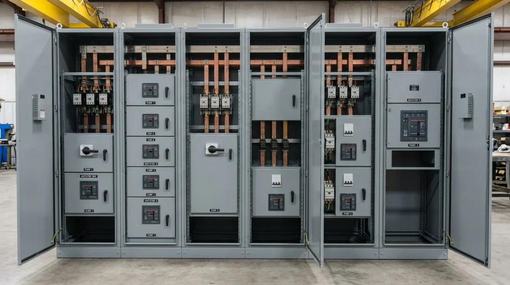
An MCC panel (Motor Control Center panel) is a centralized electrical panel used to control, protect, and monitor multiple electric motors.
Instead of installing separate motor control equipment at different locations, an MCC brings motor feeders together in one organized assembly.
A typical MCC can contain separate sections for:
- Motor starters
- Circuit breakers
- Contactors
- Overload relays
- Variable frequency drives (VFDs)
- Soft starters
- Control transformers
- Protection devices
- Monitoring equipment
- PLC interfaces
Simple Example
Consider a water treatment plant with these motors:
- Pump motor 1
- Pump motor 2
- Cooling fan motor
- Conveyor motor
- Compressor motor
Each motor needs electrical protection and control.
An MCC can contain individual compartments for these motor feeders. An operator can start or stop the required motors from the MCC or through a control system.
What Does MCC Stand For?
MCC = Motor Control Center
An MCC is mainly designed for motor control and motor power distribution.
It is different from a normal distribution panel because an MCC usually contains dedicated motor-control equipment such as starters, contactors, overload protection, VFDs, and motor feeders.
MCC Panel Working Principle
The MCC panel working principle is based on safely supplying electrical power to motors while providing control and protection.
The basic process is simple:
Power source → Main breaker → Busbars → Motor feeder → Starter/VFD → Motor
Step 1: Power Enters the MCC
Electrical power comes from an upstream switchboard, transformer, generator, or power distribution system.
The incoming supply first reaches the main incoming circuit breaker or isolator.
Step 2: Power Reaches the Busbars
Inside the MCC, electrical power is distributed through heavy conductors called busbars.
The busbars act like a common highway for electrical power.
Multiple motor feeders can receive power from these busbars.
Step 3: Each Motor Has Its Own Feeder
Every motor usually has an individual feeder section.
The feeder contains suitable switching and protection equipment.
For example:
Busbar → Circuit breaker → Contactor → Overload relay → Motor
For a VFD-controlled motor:
Busbar → Circuit breaker → VFD → Motor
Step 4: Motor Starting
When an operator gives a start command, the control circuit activates the motor starter or VFD.
A contactor closes in a conventional starter system and connects the motor to the power supply.
The VFD controls the motor electronically and can provide controlled acceleration.
Step 5: Motor Protection
Protection devices continuously monitor the motor circuit.
If excessive current occurs, the protection system can disconnect the motor.
An overload relay, for example, can protect a motor from prolonged overcurrent.
Step 6: Motor Stops
When the stop command is given, the starter or VFD disconnects or stops supplying power to the motor.
Emergency-stop circuits can also stop equipment quickly when required.
Easy Analogy
Think of an MCC as a traffic control center.
- Busbars = main roads
- Circuit breakers = safety gates
- Contactors = controlled switches
- Overload relays = safety monitors
- VFDs = speed controllers
- Motors = vehicles
Everything is organized in one place so operators and maintenance technicians can control the system safely.
Types of MCC Panels
MCC panels can be classified in several ways based on construction, voltage, installation, and motor-control technology.
1. Conventional MCC Panel
A conventional MCC uses traditional motor-control equipment such as:
- Contactors
- Overload relays
- Circuit breakers
- Starters
- Control relays
These panels are simple and widely used.
2. VFD MCC Panel
A VFD MCC includes Variable Frequency Drives for controlling motor speed.
A VFD can adjust motor speed by controlling the frequency and voltage supplied to the motor.
VFD MCCs are common where speed control and energy savings are important.
3. Soft Starter MCC Panel
A soft starter is used to reduce the high starting current and mechanical shock that can occur when a motor starts.
Soft starter MCCs are useful for pumps, fans, compressors, and other large motors.
4. Intelligent MCC
An intelligent MCC combines traditional motor control with digital monitoring and communication.
It may collect information such as:
- Motor current
- Motor status
- Fault conditions
- Energy consumption
- Operating hours
The information can be sent to a PLC, SCADA system, or building management system.
5. Fixed-Type MCC
In a fixed MCC, motor-control units are permanently connected inside the panel.
This design can be simple and economical.
However, maintenance may require more work because individual units cannot be easily removed.
6. Withdrawable MCC
Withdrawable MCCs use removable motor-control units.
A feeder can be withdrawn for maintenance while other sections remain in service, depending on the equipment design and safety procedures.
This type is popular in larger industrial installations where maintenance flexibility is important.
Main Components of an MCC Panel
Understanding the main components helps technicians troubleshoot MCCs effectively.
Main Incoming Circuit Breaker
The incoming breaker controls and protects the main electrical supply entering the MCC.
It can disconnect the entire MCC during maintenance or under fault conditions.
Busbars
Busbars distribute electrical power to individual motor feeders.
They are normally made from copper or aluminum and are designed to carry high current.
Motor Circuit Breaker
A motor feeder may use a circuit breaker or other protective switching device.
Its purpose is to provide isolation and protection against electrical faults.
Contactor
A contactor is an electrically operated switch.
It allows a motor to be started and stopped through a control circuit.
Overload Relay
An overload relay protects the motor against prolonged excessive current.
If the motor draws too much current for too long, the overload relay can trip the control circuit.
VFD
A Variable Frequency Drive controls motor speed and acceleration.
It can also provide useful motor protection and monitoring functions.
Soft Starter
A soft starter gradually increases the voltage applied to a motor during starting.
This helps reduce starting stress and current.
Control Transformer
A control transformer can provide a suitable lower control voltage for contactors, relays, indicators, and other control devices.
Push Buttons
Common push buttons include:
- Start
- Stop
- Reset
- Emergency stop
They provide manual control of motors and equipment.
Selector Switch
A selector switch allows an operator to choose operating modes such as:
- Local
- Remote
- Manual
- Automatic
Indicating Lamps
Indicator lamps show conditions such as:
- Power available
- Motor running
- Motor stopped
- Fault
- Trip
PLC Interface
Modern MCCs can communicate with a Programmable Logic Controller (PLC).
The PLC can receive motor status and send control commands.
Enclosure
The enclosure protects internal electrical equipment from accidental contact, dust, moisture, and environmental conditions.
The required enclosure design depends on the installation environment.
MCC Panel Advantages and Disadvantages
Understanding MCC panel advantages and disadvantages helps engineers choose the right motor-control arrangement.
Advantages
- Centralized motor control: Many motors can be controlled from one location.
- Better organization: Motor feeders are arranged in dedicated sections.
- Improved maintenance: Technicians can access motor-control equipment in an organized enclosure.
- Easy monitoring: Indicators and communication systems can show motor conditions.
- Protection: Breakers and overload devices protect motors and circuits.
- Automation: MCCs can connect with PLC and SCADA systems.
- Expandable design: Additional feeders can sometimes be added when the MCC is designed for future expansion.
- Reduced wiring complexity: Centralized control can simplify connections between motor feeders and control systems.
Disadvantages
- Higher initial cost: A complete MCC can cost more than basic individual motor starters.
- Large physical size: Industrial MCCs require dedicated floor or wall space.
- Installation planning: Proper power, control, ventilation, and cable routing are required.
- Maintenance requirements: Internal equipment needs regular inspection.
- Heat generation: VFDs and other equipment can produce heat inside the enclosure.
- Complexity: Intelligent MCCs require technicians with suitable electrical and control knowledge.
- Single-location dependency: A major fault in the MCC can affect multiple motor circuits.
MCC Panel Applications
MCC panels are mainly used where many motors need centralized control and protection.
Industrial Applications
MCCs are commonly used in:
- Manufacturing plants
- Cement plants
- Steel plants
- Food processing facilities
- Chemical plants
- Textile factories
- Automotive plants
- Mining facilities
- Oil and gas facilities
Water and Wastewater Plants
Water facilities use many motors for:
- Water pumps
- Sewage pumps
- Blowers
- Mixers
- Chemical dosing systems
- Sludge handling equipment
MCCs provide centralized control for these motor-driven systems.
HVAC Systems
Large buildings may use MCCs for:
- Chillers
- Cooling tower fans
- Pumps
- Large ventilation fans
- Air-handling equipment
Conveyor Systems
Factories and warehouses use motor-driven conveyors.
An MCC can control several conveyor motors while providing individual protection for each feeder.
Power Plants
Power plants use motor-control centers for auxiliary equipment such as:
- Pumps
- Fans
- Compressors
- Cooling systems
- Material-handling equipment
Modern Automation
Modern MCCs can work with:
- PLCs
- SCADA
- Industrial networks
- Remote monitoring systems
- Energy monitoring systems
- Industrial automation platforms
Difference Between MCC Panel and Distribution Panel
The difference between MCC panel and distribution panel is mainly related to their purpose.
| Feature | MCC Panel | Distribution Panel |
|---|---|---|
| Main purpose | Motor control and protection | Electrical power distribution |
| Typical load | Motors | General electrical loads |
| Contactors | Common | Usually not required |
| Overload relays | Common for motor feeders | Usually not used for general circuits |
| VFDs | Can be installed | Less common |
| Motor starters | Common | Not normally used |
| PLC integration | Common in modern systems | Possible but less central |
| Typical applications | Industrial motor systems | Buildings and general power distribution |
An MCC can distribute power, but its main purpose is motor control.
A distribution panel is mainly focused on distributing electrical power to different circuits.
MCC Panel Selection Guide
Selecting an MCC requires careful engineering.
1. Determine Motor Load
First, identify:
- Motor power
- Voltage
- Phase
- Full-load current
- Starting method
- Operating duty
2. Check Short-Circuit Requirements
The MCC must be suitable for the available fault current at its installation point.
The required short-circuit rating should be determined during electrical system design.
3. Select the Starting Method
Choose between:
- Direct-on-line starter
- Star-delta starter
- Soft starter
- VFD
The choice depends on motor size, starting current, mechanical load, process requirements, and energy goals.
4. Consider the Environment
Check whether the MCC will be installed in:
- A clean indoor room
- A dusty industrial area
- A humid environment
- An outdoor location
- A corrosive environment
The enclosure and ventilation requirements should match the site conditions.
5. Plan for Future Expansion
If more motors may be added later, reserve space and electrical capacity where practical.
6. Consider Automation
For modern plants, check whether the MCC needs:
- PLC communication
- Remote start/stop
- Motor status feedback
- Energy monitoring
- Network communication
- SCADA integration
7. Follow Applicable Standards
The MCC should be designed, manufactured, installed, and tested according to the standards and regulations applicable to the project and location.
Always use approved engineering drawings and manufacturer instructions.
Common MCC Panel Problems and Solutions
Why Is an MCC Breaker Tripping?
Possible causes include:
- Short circuit
- Motor overload
- Incorrect protection settings
- Cable fault
- Motor fault
Solution: Do not repeatedly reset the breaker. Isolate the circuit and inspect the motor, cables, protection devices, and feeder according to the site’s safety procedure.
Why Does a Motor Not Start?
Possible causes include:
- Control power failure
- Overload relay trip
- Open emergency-stop circuit
- Faulty contactor
- PLC interlock
- VFD fault
Solution: Check the control supply, fault indicators, interlocks, overload relay, contactor, and VFD display.
Why Does an Overload Relay Trip?
Possible causes include:
- Excessive mechanical load
- Low voltage
- Phase imbalance
- Motor bearing problems
- Incorrect overload setting
- Motor winding problems
Solution: Check motor current on all phases and inspect the mechanical load before resetting the overload.
Why Does a VFD Show a Fault?
VFD faults may result from:
- Overcurrent
- Overvoltage
- Undervoltage
- Overheating
- Motor problems
- Incorrect parameters
Solution: Read the VFD fault code and follow the manufacturer’s troubleshooting instructions.
Why Is an MCC Panel Getting Too Hot?
Possible causes include:
- Loose connections
- Excessive current
- Poor ventilation
- Overloaded equipment
- High ambient temperature
- VFD heat generation
Solution: Inspect connections, loading, cooling, and ventilation. Thermal inspection can help identify abnormal heating.
Important: Electrical panels can contain lethal voltages. Inspection, testing, and repair should be performed only by qualified personnel using the required isolation and safety procedures.
Future Trends in MCC Panels
MCC technology is moving toward greater automation, monitoring, and connectivity.
Smart Motor Monitoring
Modern MCCs can monitor motor conditions such as:
- Current
- Voltage
- Power
- Temperature
- Operating hours
- Fault status
This data can help maintenance teams identify problems earlier.
Predictive Maintenance
Instead of waiting for a motor to fail, monitoring systems can identify abnormal operating conditions.
This supports predictive maintenance and can reduce unexpected downtime.
Industrial Communication
Modern MCCs can communicate with automation systems through industrial communication networks.
This allows operators to view motor status and alarms from control rooms.
Energy Monitoring
Energy meters and smart motor-control equipment can help plants track electrical consumption.
This information can support energy-saving projects.
Greater VFD Adoption
VFDs are becoming increasingly common where variable-speed operation can improve process control and reduce energy use.
Digital MCCs
Future MCC systems are likely to combine:
- Motor control
- Protection
- Automation
- Communication
- Energy monitoring
- Condition monitoring
This makes the MCC an important part of modern industrial automation systems.
FAQs About MCC Panels
What is an MCC panel used for?
An MCC panel is used to control, protect, and distribute power to multiple electric motors from a centralized location.
What does MCC stand for?
MCC stands for Motor Control Center.
What is the main function of an MCC?
Its main function is to provide centralized motor control, switching, protection, and monitoring.
What is the difference between MCC and PCC?
An MCC is mainly designed for motor control, while a PCC (Power Control Center) is generally designed for larger-scale power distribution and control.
Can an MCC contain VFDs?
Yes. Modern MCCs can contain VFDs for motor speed control.
What are the main components of an MCC?
Common components include circuit breakers, busbars, contactors, overload relays, VFDs, soft starters, control transformers, push buttons, selector switches, and indicators.
Is an MCC used in homes?
MCCs are mainly used in industrial and large commercial applications. They are generally unnecessary for normal residential electrical systems because homes usually have far fewer large motors.
Conclusion
An MCC panel, or Motor Control Center, is a central part of many industrial electrical systems. It brings motor feeders, protection devices, starters, VFDs, and control equipment together in one organized location.
Understanding what is MCC panel starts with its basic purpose: safely controlling and protecting multiple motors. Its working principle is based on receiving electrical power, distributing it through busbars, controlling individual motor feeders, and protecting motors against electrical problems.
MCCs are used in factories, water treatment plants, HVAC systems, power plants, conveyors, and many automated facilities. Modern designs can also connect with PLCs, SCADA systems, communication networks, and energy-monitoring systems.
For beginners, the best way to learn MCC systems is to understand each component first and then follow the power and control circuits step by step. Always follow approved drawings, equipment ratings, applicable standards, and electrical safety procedures when working on real MCC equipment.