
Imagine traveling on a highway and seeing tall steel structures carrying thick overhead power lines across cities, rivers, mountains, and open fields. These massive structures are known as transmission towers, and they play a critical role in delivering electricity from power plants to substations over long distances. Without them, it would be impossible to supply reliable electricity to homes, industries, hospitals, schools, and businesses.
Transmission towers are one of the most important parts of an electrical power transmission system. They support high-voltage conductors safely above the ground while maintaining the required clearance for people, vehicles, and buildings. Their strong design allows them to withstand heavy winds, rain, lightning, earthquakes, and other environmental conditions.
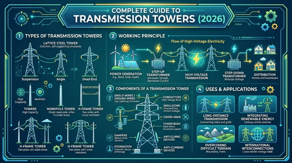
In this guide, you’ll learn what transmission towers are, the transmission towers working principle, different types, major components, and how they are used in modern power systems. Whether you are an electrical engineering student, technician, or beginner, this article explains everything in simple English with practical examples to build a strong understanding of this essential electrical infrastructure.
What Are Transmission Towers?
Transmission towers are tall steel structures designed to support overhead high-voltage power transmission lines. Their main purpose is to carry electrical conductors safely from one location to another while keeping them at a safe distance from the ground and surrounding objects.
These towers form the backbone of the electrical transmission network, allowing electricity generated at power stations to travel hundreds of kilometers before reaching substations and distribution systems.
Unlike distribution poles, transmission towers are built to carry high-voltage electricity, typically ranging from 66 kV to 765 kV or even higher for ultra-high-voltage transmission.
Simple Definition
A transmission tower is a steel framework that supports high-voltage overhead conductors and protects them from sagging, touching the ground, or coming into contact with nearby structures.
Practical Example
Suppose a hydroelectric power plant generates electricity hundreds of kilometers away from a city. The generated power is first increased to a high voltage using step-up transformers. Transmission towers then carry these high-voltage lines across forests, rivers, highways, and villages until the electricity reaches a receiving substation. From there, the voltage is reduced and distributed to consumers.
Without transmission towers, long-distance electricity transmission would not be practical or economical.
Transmission Towers Working Principle
The transmission towers working principle is based on safely supporting overhead conductors that transport electrical energy over long distances with minimum power loss.
Rather than carrying electricity themselves, transmission towers act as strong mechanical supports for conductors while maintaining proper spacing and electrical insulation.
Step-by-Step Working Principle
Step 1: Electricity Generation
Electricity is generated at power plants such as:
- Thermal power plants
- Hydroelectric plants
- Nuclear power stations
- Solar power plants
- Wind farms
Step 2: Voltage Is Increased
A step-up transformer increases the generated voltage.
Higher voltage reduces current, which minimizes power losses during long-distance transmission.
Step 3: Conductors Are Mounted on Towers
High-voltage conductors are attached to the tower using insulator strings.
The insulators prevent electricity from flowing into the steel structure.
Step 4: Towers Support the Conductors
Transmission towers carry the heavy conductors while maintaining:
- Proper ground clearance
- Safe spacing between phases
- Mechanical strength
- Stability during strong winds
Step 5: Electricity Travels Long Distances
The conductors transport electrical power across hundreds of kilometers with minimal energy loss.
The towers simply provide mechanical support throughout the transmission route.
Step 6: Voltage Is Reduced
At the receiving substation, transformers reduce the voltage before electricity enters the distribution network.
Finally, it reaches homes, factories, schools, hospitals, and commercial buildings.
Easy Analogy
Think of a transmission tower as a series of tall bridge pillars.
The bridge pillars do not transport vehicles themselves.
Instead, they support the road that allows vehicles to travel safely.
Similarly:
- Conductors carry electricity.
- Transmission towers support the conductors.
Why High Voltage Is Used
High-voltage transmission offers several advantages:
- Lower current flow
- Reduced power losses
- Smaller conductor size
- Higher transmission efficiency
- Lower operating costs
This is why transmission towers are designed for high-voltage power systems.
Types of Transmission Towers
Different transmission routes require different tower designs. Engineers select the tower type based on terrain, conductor arrangement, mechanical load, and line direction.
Suspension Transmission Tower
Suspension towers are the most commonly used transmission towers.
They support conductors along straight transmission routes with minimal angle deviation.
Features
- Lightweight construction
- Economical design
- Used on straight transmission lines
- Supports vertical conductor load
Applications
- Long-distance power transmission
- Flat terrain
- Rural transmission networks
Tension (Anchor) Tower
Tension towers are installed where transmission lines change direction or terminate.
These towers withstand high mechanical tension from the conductors.
Features
- Stronger than suspension towers
- Handles conductor pulling forces
- Suitable for line bends
Applications
- River crossings
- Mountain areas
- Line termination points
- Sharp route changes
Angle Tower
Angle towers are specifically designed for locations where transmission lines turn.
They resist side forces created by changes in conductor direction.
Features
- Supports horizontal conductor tension
- Higher structural strength
- Various angle ratings available
Applications
- Road crossings
- Curved transmission routes
- Urban power corridors
Terminal Tower
Terminal towers are placed at the beginning or end of a transmission line.
They support the complete conductor tension from one side.
Features
- Heavy-duty construction
- Supports dead-end conductors
- High mechanical stability
Applications
- Substations
- Power plants
- Line termination points
Transposition Tower
In long transmission lines, conductors are periodically exchanged between phases.
This process is called transposition.
Transposition towers support this arrangement.
Features
- Reduces electrical imbalance
- Improves system performance
- Minimizes electromagnetic interference
Applications
- Extra-high-voltage transmission systems
- Long transmission corridors
Double-Circuit Transmission Tower
Double-circuit towers carry two independent transmission circuits on a single structure.
This reduces land usage while increasing transmission capacity.
Features
- Supports six phase conductors
- Saves right-of-way
- Cost-effective
Applications
- Urban transmission systems
- High-capacity transmission corridors
- Industrial power supply
Main Components of Transmission Towers
Each transmission tower consists of several important structural and electrical components.
Understanding these parts helps explain how the entire transmission system operates safely.
Tower Body
The tower body is the main steel framework.
It provides mechanical strength and supports all other tower components.
High-strength galvanized steel protects it from corrosion and harsh weather.
Cross Arms
Cross arms extend horizontally from the tower.
They hold the conductors at safe distances from one another.
Proper spacing prevents electrical faults between phases.
Peak (Tower Top)
The tower peak is the highest section.
It usually supports the earth wire or shield wire that protects the transmission line from lightning strikes.
Conductors
Conductors carry electrical energy from one location to another.
Although they are attached to the tower, they remain electrically isolated by insulators.
Common conductor materials include:
- Aluminum
- ACSR (Aluminum Conductor Steel Reinforced)
- AAAC
- ACAR
Insulators
Insulators prevent electricity from flowing into the steel tower.
Common types include:
- Suspension insulators
- Pin insulators
- Strain insulators
- Composite insulators
They maintain electrical safety while supporting the conductor weight.
Foundation
The foundation transfers the tower’s weight to the ground.
It keeps the structure stable against:
- Wind loads
- Earthquakes
- Conductor tension
- Heavy rainfall
Concrete foundations are the most commonly used.
Earth Wire (Shield Wire)
The earth wire is installed above the phase conductors.
Its main purpose is to protect the transmission line from lightning.
When lightning strikes, the earth wire safely directs the electrical energy into the ground instead of allowing it to damage the conductors.
Danger Plates and Number Plates
These identification plates improve operational safety.
They display:
- Tower number
- Voltage level
- Warning signs
- Maintenance information
These markings help maintenance crews quickly identify each tower during inspections and repairs.
Transmission Towers Advantages
Transmission towers are the backbone of every electrical transmission network. They safely support high-voltage power lines over long distances while ensuring a continuous electricity supply. Their strong construction and efficient design make them an essential part of modern power systems.
1. Efficient Long-Distance Power Transmission
One of the biggest advantages of transmission towers is their ability to carry high-voltage electricity across hundreds of kilometers with minimal power loss.
By supporting high-voltage conductors, they help utilities transmit electricity efficiently from power plants to substations.
2. High Mechanical Strength
Transmission towers are built using galvanized steel, making them extremely strong and durable.
They are designed to withstand:
- Strong winds
- Heavy rainfall
- Snow loads
- Earthquakes
- Lightning
- High conductor tension
This ensures reliable operation even in harsh environmental conditions.
3. Supports High Voltage Levels
Unlike distribution poles, transmission towers can safely carry very high voltages, including:
- 66 kV
- 132 kV
- 220 kV
- 400 kV
- 765 kV
- Ultra High Voltage (UHV) systems
Their design provides the necessary clearance and insulation for safe operation.
4. Long Service Life
Transmission towers require relatively little maintenance and can remain in service for several decades.
With proper inspection and corrosion protection, many towers operate efficiently for 40–60 years or more.
5. Improves Grid Reliability
A well-designed transmission tower network ensures uninterrupted electricity supply.
Even under heavy electrical loads, towers maintain conductor spacing and structural stability, reducing the risk of outages.
6. Suitable for Different Terrains
Transmission towers can be installed in various environments, including:
- Mountains
- Forests
- Rivers
- Deserts
- Coastal areas
- Urban regions
Special tower designs are available for each type of terrain.
7. Easy Maintenance and Inspection
Most tower components are accessible for inspection and maintenance.
Utility companies regularly check towers for:
- Corrosion
- Loose bolts
- Damaged insulators
- Foundation stability
- Conductor condition
Routine maintenance helps improve system reliability.
8. Supports Multiple Circuits
Modern double-circuit transmission towers carry two independent power circuits on a single structure.
Benefits include:
- Reduced land usage
- Lower construction costs
- Increased transmission capacity
- Improved network flexibility
Transmission Towers Disadvantages
Although transmission towers provide many benefits, they also have some practical limitations.
1. High Installation Cost
Building a transmission line requires significant investment.
Costs include:
- Steel structures
- Foundations
- Conductors
- Insulators
- Transportation
- Construction equipment
High-voltage transmission projects require substantial capital.
2. Large Land Requirement
Transmission corridors require a wide right-of-way.
Trees and buildings must remain at safe distances from conductors, making land acquisition a major challenge in densely populated areas.
3. Visual Impact
Many people consider transmission towers visually unattractive.
Their large size can affect landscapes, especially in residential or scenic areas.
4. Weather Exposure
Transmission towers are continuously exposed to environmental conditions such as:
- Heavy storms
- Ice accumulation
- Lightning
- Flooding
- High winds
Extreme weather may increase maintenance requirements.
5. Regular Maintenance Required
Although towers have long service lives, periodic inspections remain essential.
Maintenance activities include:
- Tightening bolts
- Replacing damaged insulators
- Painting or corrosion protection
- Foundation repairs
- Vegetation management
6. Environmental Challenges
New transmission projects may affect forests, wildlife habitats, and agricultural land.
Environmental studies are often required before construction begins.
Transmission Towers Applications
The Transmission Towers applications extend far beyond simply carrying power lines. They form the backbone of national and regional electrical grids.
Residential Power Supply
Transmission towers deliver electricity from generating stations to substations that supply:
- Homes
- Apartments
- Residential communities
Without transmission towers, cities would not receive reliable electrical power.
Industrial Applications
Large industries consume enormous amounts of electricity.
Transmission towers supply power to:
- Manufacturing plants
- Steel mills
- Cement factories
- Chemical industries
- Oil and gas facilities
Reliable transmission supports continuous industrial production.
Commercial Applications
Commercial buildings depend on stable electricity supplied through transmission networks.
Examples include:
- Shopping malls
- Office buildings
- Hotels
- Hospitals
- Universities
- Airports
Renewable Energy Integration
Modern renewable energy projects rely heavily on transmission towers.
Applications include:
- Solar power plants
- Wind farms
- Hydroelectric stations
- Biomass plants
Transmission lines connect these renewable energy sources to the national grid.
Rural Electrification
Transmission towers play a major role in extending electricity to remote villages and rural communities.
They help improve:
- Education
- Healthcare
- Agriculture
- Communication
- Economic development
Cross-Border Power Transmission
Many countries exchange electricity through interconnected transmission networks.
Transmission towers support international power trading and improve regional energy security.
Difference Between Transmission Towers and Distribution Poles
Many beginners confuse transmission towers with distribution poles. Although both support overhead power lines, their purpose and design are very different.
| Feature | Transmission Towers | Distribution Poles |
|---|---|---|
| Primary Purpose | Long-distance power transmission | Local electricity distribution |
| Voltage Level | High and Extra High Voltage | Low and Medium Voltage |
| Construction Material | Galvanized steel | Concrete, steel, or wood |
| Height | 25–60 meters or more | 8–15 meters |
| Strength | Very high | Moderate |
| Conductor Size | Large conductors | Smaller conductors |
| Installation Cost | Higher | Lower |
| Typical Location | Between power plants and substations | Streets, towns, and residential areas |
| Maintenance | Specialized maintenance | Easier maintenance |
Key Difference
- Transmission towers carry electricity over long distances at high voltages.
- Distribution poles deliver electricity from substations directly to homes, businesses, and industries.
Selection Guide: How to Choose the Right Transmission Tower
Choosing the correct transmission tower depends on several engineering and environmental factors.
1. Determine the Voltage Level
Higher voltages require taller towers with greater conductor spacing and stronger insulation.
2. Consider Terrain Conditions
The tower design should match the installation location.
Examples include:
- Flat land
- Mountains
- River crossings
- Coastal regions
- Urban environments
3. Evaluate Mechanical Loads
Engineers calculate:
- Wind load
- Ice load
- Conductor tension
- Seismic forces
These factors determine the required tower strength.
4. Select the Appropriate Tower Type
Different situations require different tower designs.
- Suspension Tower – Straight transmission lines
- Angle Tower – Line direction changes
- Tension Tower – High mechanical stress
- Terminal Tower – End of transmission lines
- Double-Circuit Tower – Higher transmission capacity
5. Check Future Expansion Requirements
Utilities often plan for increasing electricity demand.
Selecting towers that allow future upgrades can reduce long-term infrastructure costs.
Tips for Beginners
- Always choose a tower rated for the required voltage.
- Consider local weather and environmental conditions.
- Use corrosion-resistant galvanized steel for long service life.
- Follow national electrical standards and safety regulations.
- Never compromise on foundation quality, as it directly affects tower stability.
- Select the correct insulator type for the transmission voltage and pollution level.
Understanding these factors helps engineers design safe, reliable, and efficient transmission systems.
Transmission Towers Advantages
Transmission towers are the backbone of every electrical transmission network. They safely support high-voltage power lines over long distances while ensuring a continuous electricity supply. Their strong construction and efficient design make them an essential part of modern power systems.
1. Efficient Long-Distance Power Transmission
One of the biggest advantages of transmission towers is their ability to carry high-voltage electricity across hundreds of kilometers with minimal power loss.
By supporting high-voltage conductors, they help utilities transmit electricity efficiently from power plants to substations.
2. High Mechanical Strength
Transmission towers are built using galvanized steel, making them extremely strong and durable.
They are designed to withstand:
- Strong winds
- Heavy rainfall
- Snow loads
- Earthquakes
- Lightning
- High conductor tension
This ensures reliable operation even in harsh environmental conditions.
3. Supports High Voltage Levels
Unlike distribution poles, transmission towers can safely carry very high voltages, including:
- 66 kV
- 132 kV
- 220 kV
- 400 kV
- 765 kV
- Ultra High Voltage (UHV) systems
Their design provides the necessary clearance and insulation for safe operation.
4. Long Service Life
Transmission towers require relatively little maintenance and can remain in service for several decades.
With proper inspection and corrosion protection, many towers operate efficiently for 40–60 years or more.
5. Improves Grid Reliability
A well-designed transmission tower network ensures uninterrupted electricity supply.
Even under heavy electrical loads, towers maintain conductor spacing and structural stability, reducing the risk of outages.
6. Suitable for Different Terrains
Transmission towers can be installed in various environments, including:
- Mountains
- Forests
- Rivers
- Deserts
- Coastal areas
- Urban regions
Special tower designs are available for each type of terrain.
7. Easy Maintenance and Inspection
Most tower components are accessible for inspection and maintenance.
Utility companies regularly check towers for:
- Corrosion
- Loose bolts
- Damaged insulators
- Foundation stability
- Conductor condition
Routine maintenance helps improve system reliability.
8. Supports Multiple Circuits
Modern double-circuit transmission towers carry two independent power circuits on a single structure.
Benefits include:
- Reduced land usage
- Lower construction costs
- Increased transmission capacity
- Improved network flexibility
Transmission Towers Disadvantages
Although transmission towers provide many benefits, they also have some practical limitations.
1. High Installation Cost
Building a transmission line requires significant investment.
Costs include:
- Steel structures
- Foundations
- Conductors
- Insulators
- Transportation
- Construction equipment
High-voltage transmission projects require substantial capital.
2. Large Land Requirement
Transmission corridors require a wide right-of-way.
Trees and buildings must remain at safe distances from conductors, making land acquisition a major challenge in densely populated areas.
3. Visual Impact
Many people consider transmission towers visually unattractive.
Their large size can affect landscapes, especially in residential or scenic areas.
4. Weather Exposure
Transmission towers are continuously exposed to environmental conditions such as:
- Heavy storms
- Ice accumulation
- Lightning
- Flooding
- High winds
Extreme weather may increase maintenance requirements.
5. Regular Maintenance Required
Although towers have long service lives, periodic inspections remain essential.
Maintenance activities include:
- Tightening bolts
- Replacing damaged insulators
- Painting or corrosion protection
- Foundation repairs
- Vegetation management
6. Environmental Challenges
New transmission projects may affect forests, wildlife habitats, and agricultural land.
Environmental studies are often required before construction begins.
Transmission Towers Applications
The Transmission Towers applications extend far beyond simply carrying power lines. They form the backbone of national and regional electrical grids.
Residential Power Supply
Transmission towers deliver electricity from generating stations to substations that supply:
- Homes
- Apartments
- Residential communities
Without transmission towers, cities would not receive reliable electrical power.
Industrial Applications
Large industries consume enormous amounts of electricity.
Transmission towers supply power to:
- Manufacturing plants
- Steel mills
- Cement factories
- Chemical industries
- Oil and gas facilities
Reliable transmission supports continuous industrial production.
Commercial Applications
Commercial buildings depend on stable electricity supplied through transmission networks.
Examples include:
- Shopping malls
- Office buildings
- Hotels
- Hospitals
- Universities
- Airports
Renewable Energy Integration
Modern renewable energy projects rely heavily on transmission towers.
Applications include:
- Solar power plants
- Wind farms
- Hydroelectric stations
- Biomass plants
Transmission lines connect these renewable energy sources to the national grid.
Rural Electrification
Transmission towers play a major role in extending electricity to remote villages and rural communities.
They help improve:
- Education
- Healthcare
- Agriculture
- Communication
- Economic development
Cross-Border Power Transmission
Many countries exchange electricity through interconnected transmission networks.
Transmission towers support international power trading and improve regional energy security.
Difference Between Transmission Towers and Distribution Poles
Many beginners confuse transmission towers with distribution poles. Although both support overhead power lines, their purpose and design are very different.
| Feature | Transmission Towers | Distribution Poles |
|---|---|---|
| Primary Purpose | Long-distance power transmission | Local electricity distribution |
| Voltage Level | High and Extra High Voltage | Low and Medium Voltage |
| Construction Material | Galvanized steel | Concrete, steel, or wood |
| Height | 25–60 meters or more | 8–15 meters |
| Strength | Very high | Moderate |
| Conductor Size | Large conductors | Smaller conductors |
| Installation Cost | Higher | Lower |
| Typical Location | Between power plants and substations | Streets, towns, and residential areas |
| Maintenance | Specialized maintenance | Easier maintenance |
Key Difference
- Transmission towers carry electricity over long distances at high voltages.
- Distribution poles deliver electricity from substations directly to homes, businesses, and industries.
Selection Guide: How to Choose the Right Transmission Tower
Choosing the correct transmission tower depends on several engineering and environmental factors.
1. Determine the Voltage Level
Higher voltages require taller towers with greater conductor spacing and stronger insulation.
2. Consider Terrain Conditions
The tower design should match the installation location.
Examples include:
- Flat land
- Mountains
- River crossings
- Coastal regions
- Urban environments
3. Evaluate Mechanical Loads
Engineers calculate:
- Wind load
- Ice load
- Conductor tension
- Seismic forces
These factors determine the required tower strength.
4. Select the Appropriate Tower Type
Different situations require different tower designs.
- Suspension Tower – Straight transmission lines
- Angle Tower – Line direction changes
- Tension Tower – High mechanical stress
- Terminal Tower – End of transmission lines
- Double-Circuit Tower – Higher transmission capacity
5. Check Future Expansion Requirements
Utilities often plan for increasing electricity demand.
Selecting towers that allow future upgrades can reduce long-term infrastructure costs.
Tips for Beginners
- Always choose a tower rated for the required voltage.
- Consider local weather and environmental conditions.
- Use corrosion-resistant galvanized steel for long service life.
- Follow national electrical standards and safety regulations.
- Never compromise on foundation quality, as it directly affects tower stability.
- Select the correct insulator type for the transmission voltage and pollution level.
Understanding these factors helps engineers design safe, reliable, and efficient transmission systems.
Common Problems & Solutions (FAQ Style)
Transmission towers are designed to operate reliably for decades, but they can still develop problems due to weather, aging, corrosion, or mechanical stress. Regular inspection and maintenance help prevent failures and ensure a stable electricity supply.
1. Why Do Transmission Towers Rust?
Problem
Steel transmission towers develop rust or corrosion over time.
Possible Causes
- High humidity
- Coastal environments
- Heavy rainfall
- Damaged galvanized coating
- Chemical pollution
Solution
- Inspect towers regularly.
- Remove rust from affected areas.
- Apply anti-corrosion paint or protective coatings.
- Replace severely corroded steel members.
2. Why Do Conductors Sag?
Problem
The transmission conductors hang lower than normal.
Possible Causes
- High ambient temperature
- Heavy electrical loading
- Aging conductors
- Improper installation
Solution
- Check conductor tension.
- Replace worn conductors if necessary.
- Adjust sag according to design standards.
- Perform periodic inspections during summer.
3. Why Do Insulators Fail?
Problem
Insulators crack, flash over, or lose insulation strength.
Possible Causes
- Lightning strikes
- Dust and pollution buildup
- Mechanical damage
- Aging materials
Solution
- Clean contaminated insulators.
- Replace damaged insulator strings.
- Install surge arresters where needed.
- Use composite insulators in polluted environments.
4. What Happens If Lightning Strikes a Transmission Tower?
Problem
Lightning can damage transmission equipment or interrupt power.
Solution
Transmission towers are equipped with earth (shield) wires that safely carry lightning current into the ground. Proper grounding and regular testing of the earthing system reduce the risk of equipment damage and outages.
5. Why Do Tower Foundations Become Weak?
Problem
Tower foundations lose stability.
Possible Causes
- Soil erosion
- Flooding
- Poor drainage
- Ground movement
Solution
- Inspect foundations regularly.
- Improve drainage around the tower.
- Reinforce or rebuild damaged foundations.
- Monitor tower alignment after heavy rains.
6. Why Are Transmission Towers Inspected Regularly?
Answer
Routine inspections help identify problems before they become serious.
Maintenance teams check for:
- Loose bolts
- Rust and corrosion
- Damaged members
- Broken insulators
- Foundation settlement
- Conductor condition
Preventive maintenance improves reliability and reduces unexpected outages.
7. Can Transmission Towers Collapse?
Answer
Yes, but tower failures are uncommon when systems are properly designed and maintained.
Possible reasons include:
- Extreme storms
- Earthquakes
- Foundation failure
- Vehicle collisions
- Structural damage
- Design overload
Modern towers are engineered with high safety factors to minimize these risks.
8. What Is the Typical Life of a Transmission Tower?
Answer
A galvanized steel transmission tower typically has a service life of 40–60 years or more when maintained properly.
Regular inspections, corrosion protection, and timely repairs can further extend its operational life.
Future Trends in Transmission Towers
As electricity demand continues to grow, transmission tower technology is becoming smarter, stronger, and more environmentally friendly.
Smart Transmission Towers
Modern utilities are installing sensors on transmission towers to monitor:
- Structural health
- Conductor temperature
- Tower tilt
- Wind speed
- Vibration
These sensors provide real-time data, allowing engineers to detect problems before they lead to failures.
Drone-Based Inspection
Instead of climbing towers, maintenance teams increasingly use drones equipped with high-resolution cameras and thermal imaging.
Benefits include:
- Faster inspections
- Improved worker safety
- Lower maintenance costs
- More accurate fault detection
AI and Predictive Maintenance
Artificial intelligence (AI) and machine learning are transforming transmission line maintenance.
By analyzing inspection data, AI systems can predict:
- Corrosion
- Component failure
- Foundation movement
- Insulator deterioration
This enables utilities to schedule maintenance before faults occur.
Stronger and Lighter Materials
Researchers are developing new materials that offer:
- Higher strength
- Lower weight
- Better corrosion resistance
- Longer service life
These innovations reduce construction costs and improve overall system reliability.
Environmentally Friendly Designs
Future transmission projects aim to reduce environmental impact by:
- Using compact tower designs
- Minimizing land requirements
- Protecting wildlife habitats
- Improving route planning
These improvements help balance energy needs with environmental conservation.
Renewable Energy Integration
As solar and wind energy continue to expand, transmission towers will play an even greater role in connecting renewable power plants to national grids.
Future transmission networks will support:
- Large solar farms
- Offshore wind projects
- Hybrid renewable systems
- Cross-border energy exchange
Reliable transmission infrastructure is essential for a cleaner and more sustainable energy future.
Conclusion
Transmission towers are one of the most important components of the electrical power system. They provide strong mechanical support for high-voltage conductors, allowing electricity to travel safely and efficiently from power plants to substations over long distances. Understanding the transmission towers working principle, different types, major components, transmission towers applications, and their advantages and disadvantages helps electrical students, engineers, and technicians build a solid foundation in power transmission. Modern transmission towers are designed to withstand harsh weather, carry higher voltages, and support growing electricity demands. With advancements such as smart sensors, drone inspections, AI-based maintenance, and renewable energy integration, transmission tower technology continues to evolve. By learning these fundamentals, you will be better prepared to design, operate, maintain, and troubleshoot modern electrical transmission systems safely and effectively.