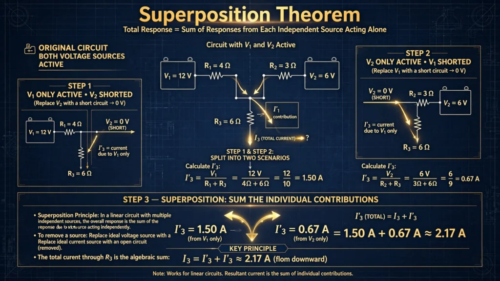

What do you do when a circuit has two or more sources pushing current in different directions? Mesh analysis works, but the equations grow with every source you add. The superposition theorem offers a calmer path: handle one source at a time, solve a simple circuit each time, then add the results together.
This guide explains the theorem in plain language, lists the rules you must follow, and works through a complete numerical example with two voltage sources.
What the Theorem States
The superposition theorem says: in any linear circuit with more than one independent source, the voltage across (or current through) any element equals the algebraic sum of the voltages (or currents) produced by each source acting alone.
“Acting alone” means you consider one source at a time while turning off all the others. Because the circuit is linear, each source contributes independently, and the contributions simply add up. It is the divide-and-conquer strategy of circuit analysis.
The Golden Rules Before You Start
Superposition is easy to apply but easy to misuse. Memorize these rules:
- Linear circuits only. Resistors, capacitors, and inductors are fine. Diodes, transistors, and saturating cores are not — superposition fails on nonlinear elements.
- One source at a time. Keep a single independent source active and deactivate the rest: voltage sources become short circuits, current sources become open circuits.
- Keep track of directions. Currents from different sources may flow in opposite directions through a resistor. Add them algebraically — same direction adds, opposite direction subtracts.
- Never superpose power. Power depends on the square of current or voltage (P = I²R), which is nonlinear. Always find the total current or voltage first, then compute power once at the end.
- Dependent sources stay on. Only independent sources are deactivated; dependent sources remain active in every sub-circuit.
Step-by-Step Method
Step 1 — Identify all independent sources. If there are N sources, you will solve N simpler circuits.
Step 2 — For each source: keep it active, turn off all others (voltage → short, current → open), and solve the resulting single-source circuit using Ohm’s law, series-parallel reduction, or Kirchhoff’s laws.
Step 3 — For the resistor of interest, note each source’s current contribution with its direction.
Step 4 — Add the contributions algebraically to get the true current, then compute anything else you need (voltage, power).
Fully Solved Example: Two Sources, One Resistor
Problem: Two voltage sources drive a shared resistor. Vs1 = 12 V connects through R1 = 6 Ω to node X; Vs2 = 6 V connects through R2 = 3 Ω to the same node X. From node X, resistor R3 = 6 Ω goes to the common ground (both sources’ negative terminals are grounded). Find the current through R3.
Source 1 acting alone (Vs1 = 12 V; Vs2 short-circuited):
Shorting Vs2 connects the bottom of R2 directly to ground. From node X, current can flow to ground through R2 (3 Ω) or R3 (6 Ω) — these two are in parallel:
R_parallel = (3 × 6) / (3 + 6) = 18 / 9 = 2 Ω
Total resistance seen by Vs1 = R1 + 2 = 6 + 2 = 8 Ω
Total current from Vs1 = 12 / 8 = 1.5 A
This 1.5 A splits at node X. Current through R3 = 1.5 × R2 / (R2 + R3) = 1.5 × 3 / 9 = 0.5 A downward.
Source 2 acting alone (Vs2 = 6 V; Vs1 short-circuited):
Now R1 (6 Ω) connects node X to ground through the shorted Vs1, in parallel with R3 (6 Ω):
R_parallel = (6 × 6) / (6 + 6) = 36 / 12 = 3 Ω
Total resistance seen by Vs2 = R2 + 3 = 3 + 3 = 6 Ω
Total current from Vs2 = 6 / 6 = 1 A
Current through R3 = 1 × R1 / (R1 + R3) = 1 × 6 / 12 = 0.5 A downward.
Add the contributions:
Both contributions flow downward through R3, so they add:
I_R3 = 0.5 + 0.5 = 1.0 A downward
(You can verify with nodal analysis: node X sits at 6 V, so 6 V / 6 Ω = 1 A through R3. It matches.)
Notice how each sub-circuit was a trivial series-parallel problem — the kind covered in any introduction to series circuits — while the original two-source circuit would have needed simultaneous equations.
Why You Cannot Superpose Power
Beginners often try to compute the power from each source separately and add the powers. This is wrong, and the math shows why: if source 1 alone drives current I1 and source 2 alone drives I2 through a resistor R, the true power is (I1 + I2)² × R = I1²R + I2²R + 2·I1·I2·R. That extra cross-term (2·I1·I2·R) is missing when you add powers directly. Always superpose currents or voltages — then compute power once.
Where Superposition Is Used
- Hand analysis — the fastest mental method for two-source DC circuits.
- AC circuits — sources at different frequencies must be analyzed separately (impedances differ per frequency) and only the time-domain results combined.
- Understanding — it reveals how much each source contributes, which is invaluable when debugging or balancing a design.
- Foundation — the idea behind superposition powers advanced tools like Fourier analysis and linear system theory.
Frequently Asked Questions
What is the superposition theorem in simple words?
Solve the circuit once for each source acting alone (others turned off), then add up the individual currents or voltages. The total response is the sum of the individual responses.
How do I turn off a voltage source vs a current source?
Replace an independent voltage source with a short circuit (0 V across it) and an independent current source with an open circuit (0 A through it). Dependent sources are never turned off.
Can I use superposition with three or more sources?
Yes. Solve one sub-circuit per source and add all the contributions. The effort grows linearly, which is exactly why the method stays attractive.
Why can’t I add powers from each source?
Power is quadratic (P = I²R), not linear. The square of a sum is not the sum of the squares — a cross-term appears. Superpose current or voltage first, then calculate power from the total.
Does superposition work for AC circuits with different frequencies?
Yes, and it is actually required there: analyze each frequency separately (since inductive and capacitive reactance change with frequency), then add the time-domain waveforms. You cannot add phasors of different frequencies directly.
What if two sources push current in opposite directions?
Subtract instead of add. Assign a reference direction, treat one contribution as positive and the opposing one as negative, and take the algebraic sum. The sign of the result tells you the true direction.
Final Thoughts
Superposition turns a tangled multi-source circuit into a set of easy single-source puzzles. Keep the five golden rules in mind — especially linearity and the no-power-adding rule — and you will solve in minutes what used to take pages of algebra. For the formal statement and its history, see the superposition theorem on Wikipedia.