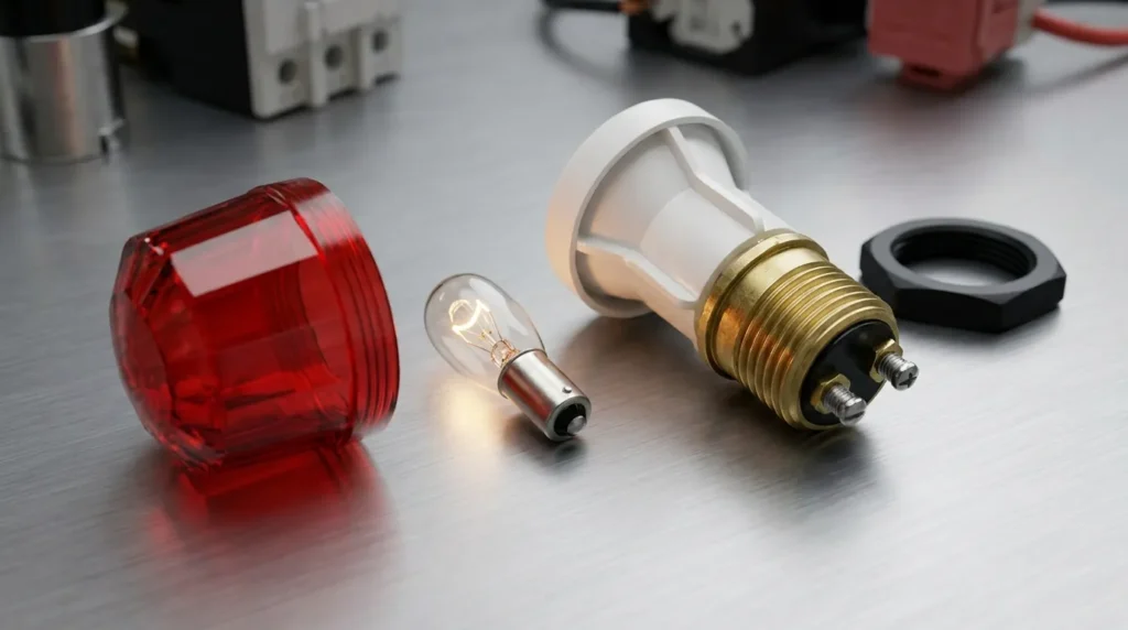

Imagine walking into an electrical control room and seeing a panel filled with switches, breakers, motors, and push buttons. How can you quickly know whether the power is ON, a motor is running, or a fault has occurred? One of the simplest answers is the indicator lamp. These small lights provide immediate visual information about the condition of an electrical circuit or machine.
An indicator lamp is a basic but important electrical component used in control panels, distribution boards, industrial machines, generators, appliances, and many other systems. It helps operators understand equipment status without opening the panel or using a measuring instrument.
For electrical students, technicians, and engineers, understanding an indicator lamp is important because it is commonly found in practical electrical installations. A correctly selected and installed lamp can improve safety, monitoring, and troubleshooting.
In this guide, you will learn what an indicator lamp is, how an indicator lamp works, its types, main components, advantages and disadvantages, applications, selection methods, common problems, troubleshooting techniques, and future trends. The explanation uses simple language so beginners can understand the concept easily.
2. What Is an Indicator Lamp?
An indicator lamp is a small electrical device that produces a visible light to show the operating condition or status of an electrical circuit, machine, or system.
In simple words, an indicator lamp acts like a visual signal. When the lamp is ON, it tells the operator that a particular electrical condition exists. When it is OFF, it may indicate that the circuit is de-energized or that the monitored condition is not present.
For example, a control panel may have:
- A green lamp to show that a motor is running.
- A red lamp to indicate a fault or stop condition.
- A yellow or amber lamp to indicate a warning.
- A white lamp to show that control power is available.
- A blue lamp for a special operating or control condition.
The exact color meaning can vary according to the machine design and applicable standards, so technicians should always check the control-panel documentation.
Simple Practical Example
Consider a water pump control panel.
When the main supply is available, a lamp labeled POWER ON may illuminate. When the pump starts, another lamp labeled PUMP RUNNING turns ON. If an overload relay trips, a red FAULT lamp may illuminate.
The operator can therefore understand the basic condition of the system simply by looking at the panel.
3. Indicator Lamp Working Principle
The indicator lamp working principle is based on converting electrical energy into visible light.
The basic operation is simple. When the correct voltage is applied to the lamp, current flows through its internal light-producing element. The element then produces light, allowing the operator to see the status of the connected circuit.
Step-by-Step Working
Step 1: Electrical Supply Is Available
The indicator lamp is connected to an electrical circuit. This may be an AC or DC control circuit depending on the lamp design.
Step 2: The Control Device Changes State
A switch, relay, contactor, push button, PLC output, or other control device completes or interrupts the circuit.
Step 3: Current Flows Through the Lamp
When the circuit is completed, current passes through the indicator lamp.
Step 4: The Lamp Produces Light
The lamp’s internal light source converts electrical energy into visible light.
Step 5: The Operator Sees the Status
The illuminated lamp provides a visual indication of the condition being monitored.
Easy Analogy
Think of an indicator lamp like a traffic signal.
A traffic light does not physically stop every vehicle itself. Instead, it gives drivers visual information about what they should do.
Similarly, an electrical indicator lamp does not normally control the machine. It simply shows the operator what is happening in the electrical system.
Example of Motor Control
A motor control circuit may use three lamps:
- Green: Motor running
- Red: Motor stopped or fault condition
- Yellow: Warning or standby condition
When the motor contactor energizes, its auxiliary contact can complete the circuit to the green lamp. The lamp illuminates and tells the operator that the motor has received the run command.
4. Types of Indicator Lamps
Indicator lamps can be classified according to their light source, voltage, mounting method, color, and application.
LED Indicator Lamp
LED indicator lamps use a light-emitting diode (LED) as their light source.
They are now widely used because they require relatively little power and generally have a long service life.
Features:
- Low power consumption
- Long operating life
- Bright light
- Fast response
- Available in many colors
- Low heat generation
LED indicators are common in modern control panels and industrial equipment.
Incandescent Indicator Lamp
Traditional incandescent indicator lamps use a small filament that becomes hot and produces light when current passes through it.
Advantages:
- Simple construction
- Familiar technology
- Warm light appearance
Limitations:
- Higher power consumption
- More heat generation
- Shorter life compared with many LED lamps
- Filament can fail due to vibration or aging
They are less common in modern control systems.
Neon Indicator Lamp
Neon indicator lamps use a gas discharge to produce visible light.
They have traditionally been used for indicating the presence of AC voltage in certain applications.
Features:
- Simple design
- Low current operation
- Useful for voltage indication
- Common in some older equipment
Modern LED indicators have replaced many neon applications.
Panel Mount Indicator Lamp
Panel mount indicators are designed to be installed directly into electrical control panels.
They normally include:
- Front indicator lens
- Mounting hardware
- Electrical terminals
- Internal light source
They are available in different sizes, colors, and voltage ratings.
Push-to-Test Indicator Lamp
Some indicator lamps include a test feature that allows an operator to verify whether the lamp is working.
When the test button is pressed, the lamp illuminates even if the normal operating condition is not active.
This is useful in control rooms and industrial panels where reliable visual indication is important.
Buzzer and Lamp Combination
Some control systems combine an indicator lamp with an audible buzzer.
The lamp provides a visual warning, while the buzzer provides an audible alert. This arrangement is useful when operators may not always be looking directly at the control panel.
5. Main Components of an Indicator Lamp
Although an indicator lamp is a small device, it contains several important parts.
Light Source
The light source produces visible light.
Depending on the design, it may be:
- LED
- Incandescent filament
- Neon gas element
Lens
The lens is the visible colored portion of the indicator.
It helps:
- Protect the internal components.
- Spread the light.
- Provide a clear visual signal.
- Identify different operating conditions through color.
Housing
The housing protects the internal electrical components from mechanical damage, dust, and accidental contact.
Terminals
Terminals provide the electrical connection between the indicator lamp and the control circuit.
Resistor or Current-Limiting Circuit
Some indicator lamps, especially LED-based designs, require current limitation. This may be provided by a resistor or another internal circuit.
Mounting Mechanism
Panel-mounted lamps use a mounting nut, clip, or similar mechanism to hold the indicator securely in the control panel.
Electrical Insulation
Insulating materials separate live electrical parts from the external housing and help prevent accidental contact.
6. Advantages of Indicator Lamps
Indicator lamps provide several practical benefits in electrical systems.
Quick Visual Information
Operators can immediately identify the status of equipment without using a multimeter.
Improved Safety
Warning and fault lamps can alert operators to abnormal conditions.
Easy Troubleshooting
A technician can quickly identify which part of a control system may not be operating correctly.
Low Cost
Indicator lamps are relatively inexpensive compared with many monitoring devices.
Easy Installation
Most panel indicators have simple electrical connections and straightforward mounting arrangements.
Multiple Status Indications
Different colors can be used to represent different conditions.
Low Power Consumption
Modern LED indicator lamps consume very little electrical power.
Long Service Life
LED-based indicators generally provide long operating life, reducing replacement frequency.
7. Disadvantages and Limitations of Indicator Lamps
Despite their usefulness, indicator lamps have some limitations.
They Do Not Provide Detailed Information
An indicator lamp normally shows only a basic condition such as ON, OFF, warning, or fault.
Lamp Failure Can Cause Confusion
If the indicator itself fails, the operator may receive incorrect information.
Color Interpretation Can Vary
The meaning of a particular color depends on the system design and applicable standards.
Requires Correct Voltage
Applying the wrong voltage can damage the indicator.
Limited Diagnostic Capability
A lamp cannot normally provide detailed electrical measurements such as current, voltage, frequency, or power consumption.
Visibility Problems
A damaged lens, strong surrounding light, or poor lamp brightness can make the indication difficult to see.
8. Indicator Lamp Applications
Indicator lamps are used in many residential, commercial, and industrial electrical systems.
Home Electrical Applications
Indicator lamps can be found in:
- Electrical appliances
- Power strips
- Battery chargers
- Inverters
- UPS systems
- Distribution boards
- Water pump controls
For example, an appliance may use an indicator lamp to show that electrical power is available.
Industrial Applications
Industrial control panels commonly use indicator lamps to show:
- Power ON
- Motor running
- Motor stopped
- Fault condition
- Overload
- Emergency stop
- Standby status
- Control circuit availability
Generator Panels
Generators often use indicator lamps for:
- Generator running
- Mains available
- Generator available
- Low oil pressure
- High temperature
- Battery charging
- Fault indication
Motor Control Centers
Motor Control Centers (MCCs) use indicator lamps to provide quick information about individual motors and feeders.
Electrical Distribution Panels
Distribution panels may use lamps to indicate the presence of voltage on different phases or the status of specific circuits.
Automation Systems
Modern automation panels use LED indicators alongside PLCs, relays, sensors, and contactors to provide quick visual feedback.
9. Indicator Lamp vs Pilot Lamp
The terms indicator lamp and pilot lamp are often used for similar devices. In many electrical applications, they perform essentially the same basic function: providing a visual indication of circuit or equipment status.
| Feature | Indicator Lamp | Pilot Lamp |
|---|---|---|
| Main purpose | Shows equipment or circuit status | Shows equipment or circuit status |
| Common location | Control panels, machines | Control panels, machines |
| Light source | Usually LED | LED, incandescent, or other |
| Color options | Many | Many |
| Typical use | Status indication | Status indication |
| Modern usage | Very common | Still commonly used |
The exact terminology can vary between manufacturers, industries, and technical documents.
10. Selection Guide
Choosing the correct indicator lamp is important for safe and reliable operation.
Check Rated Voltage
Always select a lamp designed for the actual control voltage.
Common ratings include:
- 12 V
- 24 V
- 48 V
- 110 V
- 120 V
- 220–240 V
The correct rating depends on the electrical system.
Select AC or DC Type
Check whether the control circuit uses AC or DC. Some indicators are designed for a specific type of supply, while others can accept a wider range.
Choose the Correct Color
Select colors according to the intended indication and applicable control-system standards.
Check Mounting Size
Make sure the indicator fits the panel cutout.
Consider Brightness
For industrial environments with strong lighting, choose a lamp with sufficient brightness.
Prefer LED for Many Modern Applications
LED indicators are often preferred because of their low power consumption, long life, and good visibility.
Check Environmental Rating
For outdoor, dusty, wet, or harsh industrial environments, select an indicator with an appropriate enclosure or ingress-protection rating.
Beginner Tip
Never select an indicator lamp based only on its physical appearance. Always check its voltage rating, AC/DC compatibility, mounting size, terminal arrangement, and environmental requirements.
11. Common Problems and Solutions
Q1: Why is the indicator lamp not turning ON?
Possible causes:
- No supply voltage
- Broken wire
- Faulty lamp
- Loose terminal
- Defective switch or relay contact
Solution: Check the supply voltage, wiring, terminals, and lamp condition using appropriate test equipment.
Q2: Why does the LED indicator appear dim?
Possible causes:
- Incorrect voltage
- Poor electrical connection
- Aging LED
- Incompatible control circuit
Solution: Verify the rated voltage and inspect all connections.
Q3: Why does the indicator lamp keep flickering?
Possible causes:
- Loose connection
- Unstable supply
- Faulty relay or contactor
- Incompatible LED circuit
Solution: Check the control voltage and tighten connections. Inspect the switching device if necessary.
Q4: Why does the indicator lamp burn out repeatedly?
Possible causes:
- Excessive voltage
- Incorrect lamp rating
- Voltage surges
- Excessive heat
Solution: Verify the supply voltage and select a properly rated indicator.
Q5: Why is the fault lamp ON even though the equipment appears normal?
Possible causes:
- Faulty auxiliary contact
- Incorrect control wiring
- Defective sensor
- Faulty indicator circuit
Solution: Trace the control circuit from the monitored device to the indicator and test each component.
Q6: Can an indicator lamp be used as a measuring device?
No. An indicator lamp provides a visual status signal, not an accurate measurement. Use a suitable meter or monitoring device when exact voltage, current, or power information is required.
12. Future Trends in Indicator Lamps
Indicator lamps are simple devices, but their technology continues to improve as electrical systems become more intelligent.
Smart LED Indicators
Modern LED indicators can provide clearer status information while consuming very little energy.
Multi-Color Indicators
Advanced indicators can display multiple colors from a single device, reducing the number of panel components required.
Intelligent Diagnostic Systems
Future control panels will increasingly combine visual indicators with digital monitoring systems that can provide detailed fault information.
PLC and HMI Integration
Indicator lamps will continue to work alongside Programmable Logic Controllers (PLCs) and Human-Machine Interfaces (HMIs), providing local visual feedback while digital systems provide detailed information.
Remote Monitoring
Modern industrial systems can send equipment status to remote monitoring platforms. An indicator lamp may remain as the local visual signal while sensors and controllers transmit the same information digitally.
Energy-Efficient Designs
LED technology will continue to dominate many indicator applications because of its low power consumption, long life, and high brightness.
The overall industry direction is toward smarter, brighter, more energy-efficient, and more reliable indication systems that combine traditional visual signals with modern automation and monitoring technologies.
13. Conclusion
An indicator lamp is a simple but essential electrical component that provides quick visual information about the condition of a circuit, machine, or electrical system. It can show power availability, motor operation, warning conditions, faults, and other important statuses.
The indicator lamp working principle is straightforward: when the correct electrical supply reaches the lamp, its light source produces visible light that communicates the system condition to the operator. LED indicators are now widely preferred because they offer low power consumption, long service life, and good visibility.
Understanding indicator lamp types, components, indicator lamp advantages and disadvantages, applications, selection factors, and troubleshooting methods is important for electrical students, technicians, and engineers. Whether used in a home appliance, generator panel, MCC, distribution board, or automated industrial system, a properly selected indicator lamp improves monitoring, safety, and ease of operation.