Imagine switching on a large electric motor in a factory. Instead of instantly allowing full current flow, the motor coil resists sudden changes in current. This opposition is not caused by ordinary resistance alone. It happens because of a property called inductive reactance. In AC circuits, inductive reactance plays a major role in controlling current flow, power consumption, and circuit behavior.
The Inductive Reactance Formula is one of the most important formulas in electrical engineering. It helps engineers calculate how inductors oppose alternating current. Without understanding inductive reactance, it becomes difficult to design transformers, motors, generators, filters, and industrial power systems.
Inductive reactance changes with frequency and inductance value. As frequency increases, inductive reactance also increases. This behavior is very important in AC power systems and electronic circuits.
In this article, you will learn the inductive reactance formula, inductive reactance working principle, types, components, applications, advantages and disadvantages, troubleshooting methods, comparison with capacitive reactance, and future electrical technologies related to inductive systems.
What is Inductive Reactance Formula?
Definition of Inductive Reactance
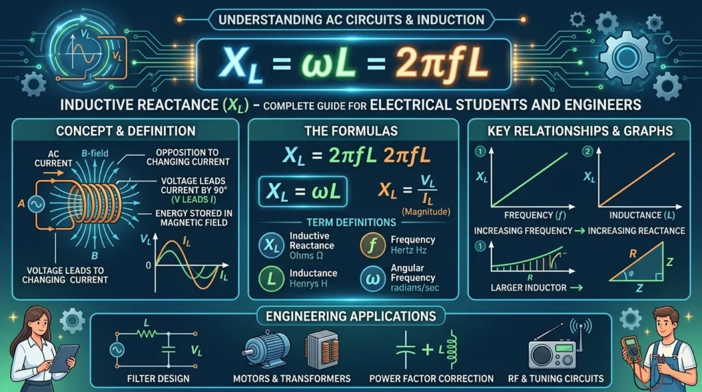
Inductive reactance is the opposition offered by an inductor to the flow of alternating current (AC). It is represented by the symbol XL and measured in Ohms (Ω).
The standard inductive reactance formula is:
X_L=2\pi fL
Where:
- (X_L) = Inductive Reactance
- (f) = Frequency in Hertz (Hz)
- (L) = Inductance in Henry (H)
- (\pi) = 3.1416
Simple Explanation
An inductor creates a magnetic field when AC current flows through it. This magnetic field opposes changes in current flow. The faster the current changes, the greater the opposition becomes.
Practical Example
Suppose:
- Frequency = 50 Hz
- Inductance = 0.2 H
Using the formula:
[
X_L = 2 \times 3.1416 \times 50 \times 0.2
]
[
X_L = 62.8\Omega
]
So the inductive reactance is approximately 62.8 Ohms.
Inductive Reactance Working Principle
The inductive reactance working principle explains how inductors oppose alternating current.
Step-by-Step Working
Step 1: AC Voltage is Applied
Alternating voltage is connected to an inductor.
Step 2: Current Starts Changing
AC current continuously changes direction and magnitude.
Step 3: Magnetic Field is Produced
The inductor coil generates a magnetic field.
Step 4: Magnetic Field Opposes Current Change
According to electromagnetic induction, the changing magnetic field creates a back EMF.
Step 5: Opposition is Created
This back EMF opposes the current flow and produces inductive reactance.
Easy Water Flow Analogy
Imagine water flowing through a heavy rotating wheel:
- Slow water flow = low opposition
- Fast changing water flow = high opposition
Similarly, higher AC frequency increases inductive reactance.
Types / Classification of Inductive Reactance
Pure Inductive Reactance
Occurs in an ideal inductor without resistance.
Features
- Current lags voltage by 90°
- No power loss
- Mostly theoretical
Practical Inductive Reactance
Occurs in real inductors containing both resistance and inductance.
Features
- Small power losses occur
- Used in real electrical systems
Low-Frequency Inductive Reactance
Occurs at lower AC frequencies.
Characteristics
- Lower opposition
- Higher current flow
High-Frequency Inductive Reactance
Occurs at higher frequencies.
Characteristics
- Higher opposition
- Lower current flow
Main Components of Inductive Reactance
Inductor Coil
The inductor is the main component producing reactance.
Function
Creates magnetic field opposition.
Frequency (f)
Frequency strongly affects inductive reactance.
Important Point
Higher frequency produces higher reactance.
Inductance (L)
Inductance measures the magnetic energy storage ability of a coil.
Unit
Henry (H)
AC Supply
Inductive reactance only exists in alternating current circuits.
Important Note
Pure DC circuits do not produce continuous inductive reactance.
Advantages of Inductive Reactance
The inductive reactance advantages and disadvantages are important in electrical engineering.
Advantages
- Controls AC current flow
- Protects electrical equipment
- Helps voltage regulation
- Essential for transformers and motors
- Used in filtering circuits
- Reduces sudden current changes
- Improves power system stability
Disadvantages / Limitations
Limitations of Inductive Reactance
- Reduces power factor
- Causes voltage drops
- Increases reactive power losses
- Creates heating in some systems
- May reduce circuit efficiency
Inductive Reactance Applications
The inductive reactance applications are extremely important in electrical and electronic systems.
Home Applications
- Ceiling fans
- Refrigerators
- Washing machines
- Air conditioners
Industrial Applications
- Electric motors
- Transformers
- Welding machines
- Industrial drives
Electronic Applications
- Filters
- Oscillators
- Amplifiers
- Signal processing circuits
Communication Systems
- Radio frequency circuits
- Antenna systems
- Wireless communication equipment
Power Systems
- Transmission networks
- Power factor correction systems
- Substations
Comparison Section
Difference Between Inductive Reactance and Resistance
| Feature | Inductive Reactance | Resistance |
|---|---|---|
| Exists In | AC circuits | AC and DC circuits |
| Symbol | XL | R |
| Depends on Frequency | Yes | No |
| Energy Loss | No ideal loss | Converts energy into heat |
| Caused By | Magnetic field | Material opposition |
Difference Between Inductive Reactance and Capacitive Reactance
| Feature | Inductive Reactance | Capacitive Reactance |
|---|---|---|
| Symbol | XL | XC |
| Component | Inductor | Capacitor |
| Frequency Effect | Increases with frequency | Decreases with frequency |
| Current Behavior | Current lags voltage | Current leads voltage |
Selection Guide
How to Choose Proper Inductive Reactance
For Beginners
- Identify operating frequency
- Measure inductance carefully
- Select proper coil rating
Engineering Tips
Match Frequency Correctly
High-frequency circuits require careful reactance calculations.
Avoid Excessive Reactance
Too much reactance reduces current excessively.
Check Coil Heating
Overloaded inductors may overheat.
Common Problems & Solutions
Problem 1: Excessive Voltage Drop
Cause
Very high inductive reactance.
Solution
Reduce inductance or operating frequency.
Problem 2: Poor Power Factor
Cause
Large inductive loads.
Solution
Use capacitor banks for correction.
Problem 3: Motor Starting Problems
Cause
Improper reactance balance.
Solution
Check motor winding condition.
Problem 4: Coil Overheating
Cause
High current or insulation damage.
Solution
Use proper cooling and insulation.
Problem 5: Signal Distortion
Cause
Incorrect inductive reactance in filters.
Solution
Use properly designed inductors.
Future Trends
Smart Electrical Systems
Modern smart grids use advanced reactance monitoring systems.
High-Frequency Electronics
5G communication and high-speed electronics require precise reactance control.
Electric Vehicles
EV motors and charging systems depend heavily on inductive reactance calculations.
Renewable Energy Systems
Solar inverters and wind turbines use inductive components for power control.
Wireless Charging Technology
Wireless power transfer systems rely on magnetic induction and reactance matching.
Conclusion
The Inductive Reactance Formula is a fundamental concept in AC electrical engineering. It explains how inductors oppose alternating current using magnetic fields. Understanding inductive reactance helps engineers design motors, transformers, filters, and power systems more efficiently.
From household appliances to industrial machines and advanced communication systems, inductive reactance plays a major role in controlling AC current behavior. Learning the inductive reactance working principle, applications, and comparison with resistance and capacitance provides a strong foundation for electrical students and technicians.
As modern technology advances toward smart grids, electric vehicles, and renewable energy systems, knowledge of inductive reactance will remain extremely important in future electrical engineering applications.