
A factory may run dozens of induction motors, pumps, compressors, fans, and other electrical equipment. These loads need useful electrical power, but many of them also draw reactive power from the electrical system. If this reactive power is not managed properly, the facility can experience a low power factor, higher current, greater losses, and possible utility penalties.
This is where an APFC panel becomes useful.
APFC stands for Automatic Power Factor Correction. An APFC panel automatically switches capacitor banks into or out of an electrical system to keep the power factor near a desired level.
For electrical students, engineers, technicians, and beginners, understanding what is APFC panel is important because power factor is a key part of industrial electrical systems. A properly designed APFC system can improve electrical efficiency and reduce unnecessary current flow.
In this guide, you will learn the APFC panel working principle, types, main components, advantages and disadvantages, applications, selection methods, common problems, troubleshooting, and future trends. The goal is to explain the system as a senior electrical engineer would explain it to a junior technician.
What Is APFC Panel?
An APFC panel is an electrical control panel that automatically improves and maintains the power factor of an electrical system by switching capacitor banks according to the reactive power demand.
APFC = Automatic Power Factor Correction
In simple words, an APFC panel measures the electrical system and decides how many capacitor steps are needed.
For example, suppose a factory has many induction motors. During operation, these motors can cause the power factor to fall.
The APFC panel detects the low power factor and connects one or more capacitor steps.
When the power factor improves, the controller can disconnect unnecessary capacitor steps.
Simple Example
Imagine a factory has a power factor of 0.75.
The facility wants to maintain a power factor closer to 0.95 or higher, depending on its design and utility requirements.
The APFC controller measures the system and connects capacitor banks.
The system may operate like this:
Low power factor → Controller detects it → Capacitor step ON → Reactive power demand is reduced → Power factor improves
If the load decreases:
Load decreases → Controller detects excess correction → Capacitor step OFF
This automatic operation is the main difference between a basic capacitor bank and an APFC system.
APFC Panel Working Principle
The APFC panel working principle is based on measuring voltage and current, calculating power factor, and automatically switching capacitor banks.
Think of an APFC panel like an automatic water tank controller.
When the water level is low, the controller turns the pump ON. When the required level is reached, it turns the pump OFF.
Similarly, an APFC controller adds capacitor steps when correction is needed and removes them when they are no longer needed.
Step 1: Electrical Load Operates
Loads such as motors, transformers, pumps, and compressors operate in the electrical system.
Many inductive loads require reactive power.
Step 2: Current Transformer Measures Current
A Current Transformer (CT) measures the current flowing through the electrical system.
The CT provides a suitable signal to the APFC controller.
Step 3: Voltage Is Measured
The APFC controller also receives a voltage signal.
By comparing voltage and current, the controller determines the electrical system’s power factor.
Step 4: Controller Checks Power Factor
The APFC relay continuously monitors the power factor.
For example:
- Target power factor = 0.95
- Actual power factor = 0.80
The controller recognizes that additional correction is required.
Step 5: Capacitor Step Is Connected
The controller activates a contactor or switching device.
This connects a capacitor bank to the electrical system.
The capacitor supplies reactive power that helps offset the reactive demand of inductive loads.
Step 6: Power Factor Improves
After the capacitor step is connected, the system’s reactive current can decrease.
The controller measures the new condition.
If more correction is needed, another capacitor step can be connected.
Step 7: Capacitor Steps Are Removed
When the load decreases, too many capacitors may cause overcorrection.
The APFC controller then disconnects capacitor steps as required.
Basic Power Flow
A simplified APFC arrangement is:
Incoming Supply → Main Breaker → Busbar → Loads
With:
APFC Panel → Capacitor Banks → Main Busbar
The APFC panel works in parallel with the main electrical loads.
What Is Power Factor?
Before understanding APFC equipment, it is important to understand power factor.
Power factor describes how effectively electrical power is being used by an AC load.
It is commonly expressed as:
Power Factor = Real Power / Apparent Power
Real power is measured in kW.
Apparent power is measured in kVA.
For an ideal resistive load, the power factor is close to 1.
Inductive loads such as motors and transformers can have a lower power factor.
Why Is Low Power Factor a Problem?
A low power factor means more current may be required to deliver the same amount of useful power.
Higher current can result in:
- Higher cable losses
- Greater voltage drop
- Increased transformer loading
- Reduced electrical system capacity
- Possible utility charges or penalties
The exact economic impact depends on the utility tariff and local electrical system.
Types of APFC Panels
APFC panels can be classified according to their switching method, application, and system requirements.
1. Contactor-Switched APFC Panel
This is a common type of APFC system.
The controller operates contactors to connect and disconnect capacitor steps.
It is suitable for many conventional industrial applications.
Advantages include:
- Simple operation
- Familiar technology
- Easy maintenance
- Cost-effective design
2. Thyristor-Switched APFC Panel
Thyristors or solid-state switching devices can switch capacitor steps much faster than conventional contactors.
This is useful when the electrical load changes rapidly.
Typical applications include facilities with rapidly changing loads.
3. Fixed Capacitor Bank
A fixed capacitor bank is connected permanently or switched as a fixed step.
It is not the same as a fully automatic APFC system.
Fixed correction may be suitable when the reactive load is relatively stable.
4. Automatic Step APFC Panel
This panel contains multiple capacitor steps.
For example:
- 10 kVAR
- 20 kVAR
- 20 kVAR
- 40 kVAR
The controller selects the required combination.
This provides better correction than using one large fixed capacitor.
5. Detuned APFC Panel
A detuned APFC system uses reactors with capacitor banks.
The reactors help reduce the risk of resonance and can provide protection in systems where harmonics are a concern.
This type requires proper engineering based on the electrical system’s harmonic conditions.
6. Hybrid APFC System
A hybrid design can combine different switching technologies or correction methods.
It may be used when a facility has both slowly changing and rapidly changing loads.
Main Components of an APFC Panel
An APFC panel contains several important electrical and control components.
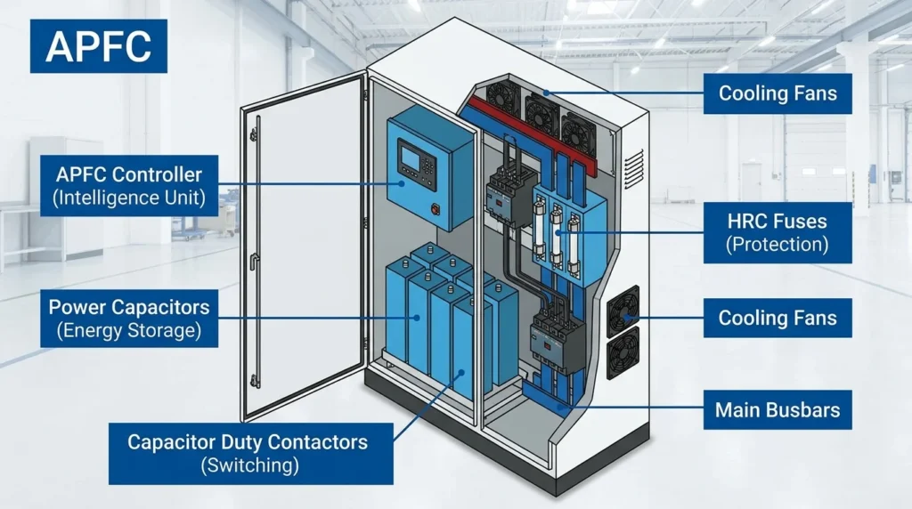
APFC Controller
The APFC controller is the brain of the system.
It measures electrical conditions and decides when to connect or disconnect capacitor steps.
It may display:
- Power factor
- Voltage
- Current
- Reactive power
- Capacitor step status
- Alarm conditions
Capacitor Banks
Capacitors provide reactive power compensation.
They are installed in multiple steps so the controller can select the amount of correction required.
Contactors
In conventional APFC panels, contactors switch capacitor steps ON and OFF.
Special capacitor-duty contactors may be used according to the panel design.
Current Transformer
The CT provides current information to the APFC controller.
Correct CT selection and installation are essential for accurate operation.
MCCB or Circuit Breaker
A circuit breaker provides protection and isolation for the APFC panel or its sections.
The exact protective device depends on the system design.
HRC Fuses
Fuses may be used to provide individual capacitor-step protection.
Their selection must match the capacitor and system requirements.
Detuned Reactors
Reactors may be installed with capacitor banks where harmonic conditions require a detuned design.
Busbars
Busbars distribute electrical power within the APFC panel and connect capacitor steps to the appropriate circuit.
Discharge Resistors
Capacitors can retain electrical charge after disconnection.
Discharge devices help reduce the capacitor voltage after the capacitor is disconnected.
The discharge time and safety requirements should follow the equipment specifications and applicable standards.
Indicating Lamps
Indicator lamps can show:
- Incoming power
- Capacitor step ON
- Capacitor step OFF
- Fault
- Alarm
Cooling Fan
Capacitor banks, reactors, contactors, and other components can generate heat.
Ventilation or cooling may be required depending on the panel size and installation conditions.
Enclosure
The enclosure protects the components from accidental contact and environmental conditions.
Its design should match the installation environment.
APFC Panel Advantages and Disadvantages
Understanding APFC panel advantages and disadvantages helps engineers determine whether automatic power factor correction is suitable.
Advantages
- Improves power factor: The main purpose is to reduce reactive power demand from the supply.
- Reduces current: Better power factor can reduce current for the same real power.
- Reduces electrical losses: Lower current can reduce resistive losses in cables and transformers.
- Improves system capacity: Lower current can free capacity in electrical equipment.
- Automatic operation: The controller adjusts capacitor steps without constant manual intervention.
- Reduces possible utility penalties: Where tariffs include power-factor charges, correction can reduce such costs.
- Improves voltage performance: Reduced reactive current can help voltage conditions in some systems.
- Better load management: The system continuously responds to changing load conditions.
Disadvantages and Limitations
- Initial investment: An APFC panel requires controllers, capacitors, switching equipment, protection, and enclosure.
- Maintenance required: Capacitors and contactors can wear or degrade over time.
- Harmonic concerns: Capacitors can interact with system harmonics and create resonance problems if the system is not properly designed.
- Overcorrection: Incorrect settings can cause leading power factor.
- Heat: Capacitors, reactors, and switching devices can produce heat.
- Capacitor aging: Capacitor performance can decrease with age and high temperature.
- Incorrect CT installation: A wrongly installed CT can cause the controller to make incorrect decisions.
- Not suitable for every load: The required correction depends on the actual electrical system.
APFC Panel Applications
APFC panel applications are common wherever large inductive loads operate.
Industrial Plants
Factories often use APFC panels to manage power factor caused by:
- Induction motors
- Pumps
- Compressors
- Fans
- Conveyors
- Transformers
Manufacturing Facilities
Manufacturing plants may have many motors starting and stopping throughout the day.
An automatic system can adjust capacitor steps according to changing electrical demand.
Commercial Buildings
Large buildings may use APFC systems where significant inductive loads exist.
Applications include:
- HVAC systems
- Chillers
- Pumps
- Large ventilation systems
- Elevators
Water Treatment Plants
Water facilities often have large pumps and motors.
APFC systems can help manage reactive power demand from these loads.
Power Plants
Power-generation facilities can use power factor correction equipment for suitable auxiliary electrical systems.
Data Centers
Large data centers have complex electrical systems and power-conditioning equipment.
Power factor management may form part of the overall electrical distribution strategy.
Renewable Energy Systems
Power factor control can also be important in systems connected to modern electrical grids.
However, correction requirements depend on the specific grid connection, inverter system, and project design.
Difference Between APFC Panel and Capacitor Bank
The difference between APFC panel and capacitor bank is mainly the way the correction is controlled.
A fixed capacitor bank may remain connected continuously, while an APFC panel automatically switches capacitor steps according to the load.
| Feature | APFC Panel | Fixed Capacitor Bank |
|---|---|---|
| Operation | Automatic | Fixed or manually switched |
| Capacitor steps | Multiple | Usually fixed |
| Controller | Yes | Usually no APFC controller |
| Response to load | Automatic | Limited |
| Overcorrection control | Better | More difficult |
| Suitable for changing loads | Yes | Less suitable |
| Cost | Higher | Lower |
| Maintenance | Higher | Lower |
| Monitoring | Available | Limited |
Difference Between APFC Panel and MCC Panel
The difference between APFC panel and MCC panel is their purpose.
| Feature | APFC Panel | MCC Panel |
|---|---|---|
| Main purpose | Power factor correction | Motor control |
| Main equipment | Capacitors and APFC controller | Starters, breakers, VFDs |
| Controls motors directly | No | Yes |
| Main objective | Reduce reactive power demand | Start, stop, and protect motors |
| Controller | APFC relay/controller | May use PLC or control circuits |
| Capacitor banks | Main feature | Not normally the main feature |
| Application | Power factor management | Motor systems |
A factory may use both systems together.
A simplified arrangement could be:
Transformer → PCC → MCC → Motors
with:
APFC Panel → Capacitor Banks → Main Busbar
APFC Panel Selection Guide
Selecting an APFC panel requires more than simply choosing a capacitor size.
1. Measure Existing Power Factor
Start by measuring the actual operating power factor.
Do not guess the required capacitor size.
2. Determine Maximum Demand
Review:
- kW demand
- kVA demand
- Existing power factor
- Load variation
- Operating hours
3. Calculate Required kVAR
The required capacitor size depends on the existing and desired power factors.
A commonly used calculation is:
Qc = P × (tan φ₁ − tan φ₂)
Where:
- Qc = required reactive power compensation in kVAR
- P = real power in kW
- φ₁ = existing power-factor angle
- φ₂ = desired power-factor angle
A qualified engineer should verify the calculation using actual site measurements.
4. Check Load Variation
If the load changes frequently, use multiple capacitor steps rather than one large fixed capacitor.
5. Check Harmonics
This is very important in modern facilities.
Loads such as VFDs, UPS systems, rectifiers, and power electronic equipment can create harmonics.
If harmonic levels are significant, a standard capacitor bank may not be appropriate without additional analysis.
6. Select the Switching Method
Choose between:
- Contactor switching
- Thyristor switching
- Hybrid solutions
Slowly changing loads may suit contactor switching, while rapidly changing loads may benefit from faster switching.
7. Consider Future Expansion
If the plant may add more motors or electrical equipment, allow suitable capacity for future requirements.
8. Check Environmental Conditions
Consider:
- Ambient temperature
- Dust
- Humidity
- Ventilation
- Installation location
High temperature can reduce capacitor life.
Common APFC Panel Problems and Solutions
Why Is the APFC Panel Not Improving Power Factor?
Possible causes include:
- Incorrect CT connection
- Wrong controller settings
- Failed capacitor step
- Blown fuse
- Faulty contactor
- Incorrect capacitor sizing
Solution: Check the controller readings, CT installation, capacitor-step status, fuses, and contactors according to the approved design and safety procedures.
Why Are Capacitors Not Switching ON?
Possible causes include:
- Controller fault
- No control supply
- Incorrect power-factor setting
- Faulty contactor
- Blown fuse
- Capacitor-step fault
Check the controller alarm and individual step status.
Why Does the APFC Show Leading Power Factor?
This usually means too much capacitance is connected for the current load.
Possible causes include:
- Excessive capacitor steps
- Incorrect controller settings
- Very low load
- Incorrect CT signal
The controller settings and capacitor-step operation should be checked.
Why Are APFC Capacitors Getting Hot?
Possible causes include:
- Harmonics
- High ambient temperature
- Overvoltage
- Excessive switching
- Poor ventilation
- Aging capacitors
If harmonics are suspected, a proper harmonic assessment should be performed.
Why Does the APFC Contactor Fail Frequently?
Frequent switching can cause contactor wear.
Possible causes include:
- Rapid load changes
- Incorrect step size
- Improper switching delay
- High inrush current
- Wrong contactor type
The APFC controller settings and capacitor switching arrangement should be reviewed.
Why Does the APFC Controller Show the Wrong Power Factor?
Possible causes include:
- Incorrect CT ratio
- CT installed on the wrong phase
- Incorrect phase relationship
- Incorrect controller configuration
- Wiring problem
Verify the CT ratio, polarity, phase connection, and controller settings against the electrical drawings.
Important Safety Note
APFC panels contain capacitors that can remain electrically charged after the incoming supply is disconnected. Never assume a capacitor is safe simply because the main breaker is OFF.
Qualified personnel should follow proper isolation, discharge, testing, lockout/tagout, and site safety procedures before working inside an APFC panel.
Future Trends in APFC Panels
APFC technology is becoming more intelligent as industrial electrical systems become more automated.
Smart Power Factor Monitoring
Modern controllers can provide detailed information about:
- Power factor
- kW
- kVAR
- kVA
- Voltage
- Current
- Frequency
- Capacitor status
Remote Monitoring
Advanced APFC systems can communicate with energy-management systems and industrial networks.
Technicians can monitor performance from a control room.
Harmonic Monitoring
As more VFDs, UPS systems, and electronic loads are installed, harmonic monitoring is becoming increasingly important.
Modern systems may monitor harmonic conditions and provide alarms.
Faster Switching
Thyristor-based systems can respond rapidly to changing loads.
This is useful in applications where conventional contactor switching may be too slow.
Predictive Maintenance
Smart monitoring can help identify:
- Capacitor degradation
- Excessive temperature
- Abnormal switching
- Harmonic problems
- Poor power factor
Early detection can reduce unexpected failures.
Energy Management Integration
APFC panels can become part of wider energy-management systems.
Data from the APFC can be combined with information from meters, PLCs, and SCADA systems to improve overall electrical-system management.
Smarter Capacitor Technologies
Modern capacitor designs continue to focus on longer service life, improved safety, and better performance under demanding electrical conditions.
FAQs About APFC Panels
What is an APFC panel?
An APFC panel is an automatic power factor correction panel that switches capacitor banks according to the reactive power demand of an electrical system.
What does APFC stand for?
APFC stands for Automatic Power Factor Correction.
What is the main purpose of an APFC panel?
Its main purpose is to improve and maintain the power factor by automatically connecting and disconnecting capacitor steps.
Why are capacitors used in APFC panels?
Capacitors provide reactive power compensation that helps offset the reactive power demand of many inductive loads.
What is the difference between APFC and a normal capacitor bank?
An APFC system automatically controls multiple capacitor steps. A basic capacitor bank may be fixed or manually switched.
Can an APFC panel reduce electricity bills?
It can reduce power-factor-related charges where the electricity tariff includes such charges. It may also reduce current and system losses, but actual savings depend on the installation and utility tariff.
How do I select an APFC panel?
Measure the existing load, power factor, kW, load variation, and harmonic conditions. Then calculate the required kVAR and select suitable capacitor steps, protection, switching equipment, and enclosure.
Can APFC panels be used with VFDs?
Yes, but the system must be properly engineered because VFDs can introduce harmonics. Harmonic analysis may be required before selecting capacitor equipment.
Conclusion
An APFC panel is an important electrical system used to automatically improve power factor. It measures the electrical system and switches capacitor banks according to the reactive power requirement.
The basic APFC panel working principle is easy to understand: measure the system, compare the actual power factor with the target, connect the required capacitor steps, and disconnect them when they are no longer needed.
APFC panels are widely used in factories, commercial buildings, water treatment plants, power facilities, and other installations with significant inductive loads. Their benefits can include lower current, reduced electrical losses, better system capacity, and reduced power-factor charges where applicable.
However, APFC systems must be correctly sized and installed. Harmonics, temperature, CT wiring, capacitor aging, and overcorrection must all be considered.
For beginners, start by learning power factor, kW, kVA, and kVAR. Once these concepts are clear, understanding APFC panels and their operation becomes much easier.