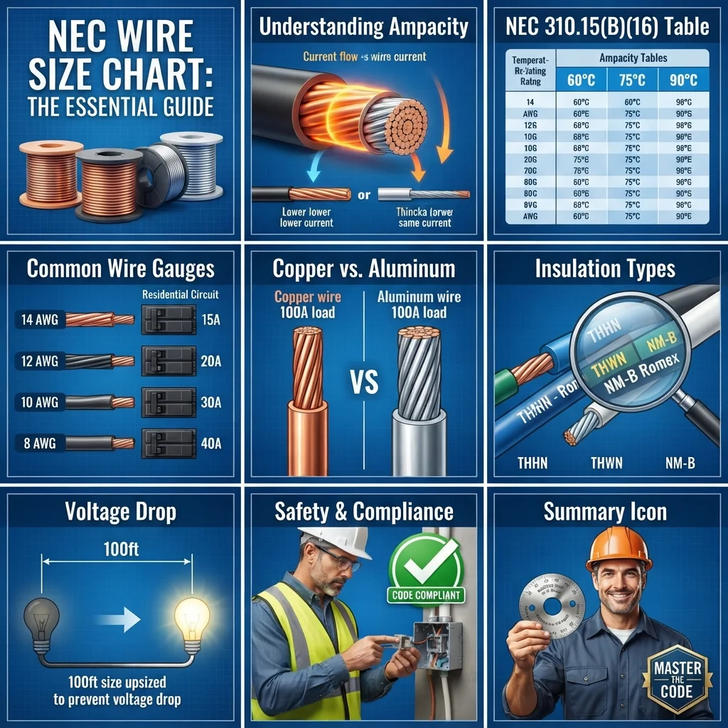

Imagine installing a 20-amp circuit in a workshop and choosing a wire simply because it “looks thick enough.” The circuit may work at first, but an incorrectly sized conductor can overheat, damage insulation, or create a serious fire hazard. This is why electricians and engineers use the NEC Wire Size Chart when selecting conductors for electrical installations.
The National Electrical Code (NEC) provides rules for determining conductor ampacity, overcurrent protection, temperature limitations, and other wiring requirements. Wire size is not selected by amperage alone. Factors such as conductor material, insulation temperature rating, ambient temperature, number of current-carrying conductors, terminal ratings, voltage drop, and installation conditions can all affect the final selection.
This guide explains the NEC Wire Size Chart in simple language. You will learn what the chart means, how wire ampacity works, common copper and aluminum wire sizes, temperature ratings, conductor types, derating, voltage drop, applications, and common sizing mistakes. The goal is to help students, technicians, and beginners understand how professional wire sizing is approached.
What Is the NEC Wire Size Chart?
The NEC Wire Size Chart is a reference used to determine the allowable ampacity of electrical conductors under specified installation conditions.
In simple terms, ampacity means the maximum current a conductor can carry continuously under particular conditions without exceeding its permitted temperature.
A larger conductor generally has greater current-carrying capacity because it has lower electrical resistance.
For example, a copper conductor may have a higher allowable ampacity when its size increases from 12 AWG to 10 AWG.
The NEC contains several tables and rules related to conductor sizing. One important reference for common insulated conductors is NEC Table 310.16, which provides allowable ampacities for conductors under specified conditions.
Practical Example
Suppose a circuit requires a conductor capable of carrying a particular load.
You cannot simply say:
“The load is 40 amps, so I need any wire rated for 40 amps.”
Instead, you must consider:
- Conductor material
- Wire size
- Insulation temperature rating
- Terminal temperature rating
- Number of current-carrying conductors
- Ambient temperature
- Installation method
- Overcurrent protection
- Voltage drop
- Specific NEC requirements
The chart provides the starting point, but the complete NEC calculation determines the final conductor size.
NEC Wire Size Chart Working Principle
The NEC Wire Size Chart working principle is based mainly on conductor ampacity.
A conductor produces heat when current flows through its resistance. If too much current passes through a conductor for its installation conditions, the conductor can become excessively hot.
The NEC establishes limits to help keep conductor temperatures within acceptable levels.
Step-by-Step Wire Sizing
1. Determine the Load
First, identify the electrical load.
Examples include:
- Lighting
- Receptacles
- Motors
- Heaters
- Air conditioners
- Industrial machines
- EV charging equipment
2. Determine Required Circuit Current
Calculate or determine the expected current.
For a simple resistive single-phase load:
Current = Power ÷ Voltage
For example, a 2,400-watt load operating at 120 volts draws approximately:
2,400 ÷ 120 = 20 amps
This does not automatically mean that every 20-amp circuit can use any conductor rated exactly 20 amps. Other NEC rules must still be checked.
3. Select a Conductor Size
Use the applicable NEC ampacity table to find a conductor with suitable ampacity.
4. Check Temperature Ratings
The conductor may have a 60°C, 75°C, or 90°C insulation rating.
However, the usable ampacity depends on the applicable rules and the temperature rating permitted for the terminals and equipment.
5. Apply Adjustment and Correction Factors
Ampacity may need to be reduced because of:
- High ambient temperature
- Multiple current-carrying conductors
- Other installation conditions
6. Check Overcurrent Protection
The conductor must be properly protected by the circuit’s overcurrent protective device.
7. Check Voltage Drop
Voltage drop should be evaluated, especially on long circuits and sensitive equipment.
Easy Analogy
Think of a wire as a water pipe.
A small pipe cannot comfortably carry a large amount of water. Similarly, a small conductor has limitations on how much electrical current it can safely carry.
A larger wire acts like a larger pipe and generally provides a greater path for current.
NEC Wire Size Chart
The following simplified chart shows common copper conductor ampacities from NEC Table 310.16 under typical reference conditions. It is intended for learning and preliminary selection, not as a substitute for the complete NEC requirements.
| Copper Wire Size | 60°C Ampacity | 75°C Ampacity | 90°C Ampacity* |
|---|---|---|---|
| 14 AWG | 15 A | 20 A | 25 A |
| 12 AWG | 20 A | 25 A | 30 A |
| 10 AWG | 30 A | 35 A | 40 A |
| 8 AWG | 40 A | 50 A | 55 A |
| 6 AWG | 55 A | 65 A | 75 A |
| 4 AWG | 70 A | 85 A | 95 A |
| 3 AWG | 85 A | 100 A | 115 A |
| 2 AWG | 95 A | 115 A | 130 A |
| 1 AWG | 110 A | 130 A | 150 A |
| 1/0 AWG | 125 A | 150 A | 170 A |
| 2/0 AWG | 145 A | 175 A | 195 A |
| 3/0 AWG | 165 A | 200 A | 225 A |
| 4/0 AWG | 195 A | 230 A | 260 A |
*The 90°C column is commonly useful for adjustment and correction calculations where permitted. It does not automatically mean the circuit can be protected at that ampacity.
Important Note About the Chart
The 75°C column is commonly used for many modern installations when the equipment terminals are rated for 75°C and the applicable NEC conditions allow it.
For smaller conductors, special requirements can limit the allowable ampacity. For example, NEC 240.4(D) places additional limits on many small conductors.
Therefore, never select a breaker simply by looking at the highest number in the 90°C column.
Types / Classification of Wire in NEC Sizing
Wire can be classified in several ways.
Copper Wire
Copper is widely used because it has:
- Good electrical conductivity
- Good mechanical strength
- Reliable connections
- Relatively compact conductor sizes
Copper is common in residential, commercial, and industrial wiring.
Aluminum Wire
Aluminum conductors are lighter than copper and can be economical for larger installations.
They are commonly found in:
- Service conductors
- Feeders
- Large distribution systems
- Utility applications
Aluminum conductors require properly rated terminals and installation practices.
Solid Wire
Solid conductors consist of one solid metal conductor.
They are commonly used in smaller fixed wiring applications.
Stranded Wire
Stranded conductors consist of multiple smaller wires twisted together.
They are useful where flexibility is needed, especially in equipment wiring and larger conductors.
Thermoplastic Insulated Wire
Common insulation types include THHN and THWN/THWN-2 conductors.
The exact properties depend on the conductor marking and listing.
Thermoset Insulated Wire
Some conductors use thermoset insulation systems designed for particular temperature and environmental conditions.
The insulation type affects where the conductor can be installed and which ampacity rules apply.
Main Components of an NEC Wire Sizing System
The NEC Wire Size Chart is only one part of a complete electrical design.
Conductor
The conductor carries electrical current.
Its size is commonly expressed using American Wire Gauge (AWG) for smaller conductors and larger circular-mil sizes for larger conductors.
Insulation
Insulation surrounds the conductor and prevents unwanted electrical contact.
Its temperature and environmental ratings are important during wire selection.
Overcurrent Protective Device
A circuit breaker or fuse protects conductors from excessive current under applicable conditions.
The protective device must be coordinated with the conductor and circuit requirements.
Terminals
Terminals connect conductors to breakers, switches, equipment, and other components.
Terminal temperature ratings can affect which ampacity column may be used.
Raceway
A raceway can protect and route conductors.
Examples include:
- Conduit
- Cable tray
- Other recognized wiring methods
The installation method can influence conductor ampacity calculations.
Electrical Load
The load consumes electrical energy.
Its current requirement determines the starting point for conductor selection.
Advantages of Using the NEC Wire Size Chart
Using the NEC requirements correctly provides several important benefits.
- Improves electrical safety by helping prevent conductor overheating.
- Supports proper circuit design for residential, commercial, and industrial systems.
- Helps select suitable conductors for expected loads.
- Improves reliability when conductor and protective-device ratings are properly coordinated.
- Reduces installation errors by providing standardized sizing information.
- Helps engineers and electricians communicate using recognized conductor sizes and ampacity values.
- Supports code compliance when all applicable NEC rules are followed.
The biggest benefit is not simply choosing a “bigger wire.” It is selecting a conductor that is suitable for the complete electrical installation.
Disadvantages / Limitations
The NEC Wire Size Chart is extremely useful, but it has limitations.
The Chart Alone Is Not Enough
A single table cannot account for every installation condition.
Additional NEC sections and tables may be required.
Temperature Can Change Ampacity
High ambient temperatures can reduce allowable conductor ampacity.
Multiple Conductors Can Affect Ampacity
When several current-carrying conductors share a raceway or cable, adjustment factors may apply.
Voltage Drop Is a Separate Consideration
A conductor can meet an ampacity requirement but still produce excessive voltage drop on a long circuit.
Equipment Ratings Matter
The conductor insulation may have a high temperature rating, but the equipment terminals may limit the usable ampacity.
Local Requirements May Differ
The applicable NEC edition and local amendments should always be confirmed before designing or installing a circuit.
NEC Wire Size Chart Applications
The NEC Wire Size Chart applications cover a wide range of electrical systems.
Residential Applications
Wire sizing is important for:
- Lighting circuits
- Receptacle circuits
- Kitchen equipment
- Water heaters
- Air-conditioning systems
- Electric dryers
- Electric ranges
- Garage circuits
Each circuit must be designed according to its load and applicable NEC requirements.
Commercial Applications
Commercial buildings contain larger and more complex electrical systems.
Applications include:
- Distribution panels
- Feeders
- HVAC equipment
- Lighting systems
- Emergency systems
- Commercial kitchens
- Office equipment
Industrial Applications
Industrial facilities often have high-current loads.
Examples include:
- Motors
- Pumps
- Compressors
- Conveyors
- Welding equipment
- Control panels
- Production machinery
Motor circuits also require additional considerations beyond simple load-current calculations.
Modern Technology
Modern installations increasingly include:
- Electric vehicle chargers
- Solar power systems
- Battery storage
- Data centers
- Variable-speed drives
- Smart building systems
These applications can have continuous loads, sensitive electronics, or special installation requirements.
Difference Between Wire Size and Ampacity
Beginners often think wire size and ampacity mean the same thing.
They do not.
| Feature | Wire Size | Ampacity |
|---|---|---|
| Meaning | Physical electrical conductor size | Allowable current capacity under specified conditions |
| Common unit | AWG or circular mils | Amperes |
| Main factor | Conductor dimensions | Size, material, insulation, temperature, installation |
| Example | 10 AWG copper | 35 A at 75°C under specified table conditions |
| Can conditions change it? | Physical size does not change | Yes |
This distinction is important.
A 10 AWG conductor does not have one universal ampacity for every installation.
Difference Between Copper and Aluminum Wire
| Feature | Copper | Aluminum |
|---|---|---|
| Conductivity | Higher | Lower |
| Weight | Heavier | Lighter |
| Typical use | Branch circuits and many building applications | Larger feeders and services |
| Required size for similar ampacity | Generally smaller | Generally larger |
| Connection considerations | Relatively straightforward | Requires properly rated equipment and installation practices |
The choice depends on cost, installation conditions, equipment requirements, conductor size, and project design.
Selection Guide
Choosing the correct wire requires more than finding a number on a chart.
Step 1: Identify the Load
Find the equipment’s rated current or calculate the required current.
Step 2: Determine Continuous Loads
A continuous load can require special treatment under NEC rules.
Do not simply size a circuit based on the equipment’s normal operating current without checking the applicable requirements.
Step 3: Select Conductor Material
Choose copper or aluminum based on the project requirements.
Step 4: Check the Insulation Rating
Look at the conductor marking.
Common temperature ratings include:
- 60°C
- 75°C
- 90°C
Use the temperature rating permitted by the applicable NEC rules and equipment terminals.
Step 5: Check Adjustment Factors
Count the applicable current-carrying conductors and check the installation temperature.
Step 6: Check Voltage Drop
For long runs, calculate voltage drop.
A larger conductor may be needed even when the basic ampacity calculation appears acceptable.
Step 7: Select the Protective Device
Choose the breaker or fuse according to the applicable NEC requirements.
Beginner Tip
Never use an online wire-size calculator as the only design authority. Use it as a learning or preliminary tool, then verify the result against the applicable NEC requirements and equipment documentation.
Common Problems & Solutions
What wire size should I use for a 20-amp circuit?
A 12 AWG copper conductor is commonly associated with a 20-amp branch circuit, but the complete installation must satisfy all applicable NEC rules.
Do not assume that every circuit carrying 20 amps can automatically use 12 AWG under every condition.
Can I use 90°C ampacity directly?
Not necessarily.
The 90°C rating can be useful for adjustment and correction calculations when permitted, but terminal and other NEC requirements can restrict the final allowable ampacity.
Why is my wire getting hot?
Possible causes include:
- Excessive current
- Loose connections
- Undersized conductors
- High ambient temperature
- Too many current-carrying conductors
- Damaged equipment
- Poor termination
Disconnect and investigate unsafe equipment using appropriate electrical safety procedures.
Does a larger wire always solve the problem?
No.
A larger conductor may reduce conductor resistance and voltage drop, but it does not automatically correct every circuit-design problem.
The breaker, terminals, equipment ratings, raceway, and installation method must also be suitable.
How does temperature affect wire size?
Higher ambient temperatures can reduce allowable conductor ampacity.
Correction factors may therefore be required.
Why does voltage drop matter?
Long conductors have resistance.
As current flows through that resistance, some voltage is lost.
Excessive voltage drop can cause:
- Poor motor performance
- Reduced lighting performance
- Equipment malfunction
- Increased energy losses
Can I use the same wire size for every circuit?
No.
Different loads have different current requirements and installation conditions.
Always size each circuit based on its actual design requirements.
What is the difference between AWG and ampacity?
AWG identifies conductor size.
Ampacity describes how much current the conductor is permitted to carry under specified conditions.
They are related but not identical.
Future Trends in Wire Sizing
Electrical systems are becoming more complex as electrification increases.
Electric Vehicle Charging
EV chargers can create significant continuous electrical loads.
Engineers must carefully evaluate conductor ampacity, voltage drop, equipment ratings, and circuit protection.
Solar and Battery Systems
Renewable-energy systems require careful conductor selection on both AC and DC sides.
Temperature, environmental exposure, installation method, and equipment ratings become especially important.
Smart Electrical Design
Modern software can help engineers perform:
- Load calculations
- Voltage-drop calculations
- Ampacity calculations
- Short-circuit studies
- Conductor coordination
- Power-system analysis
However, software does not replace engineering judgment or code verification.
Higher-Efficiency Buildings
Modern buildings use more electronic equipment, heat pumps, EV charging, automation, and distributed energy systems.
This increases the importance of accurate load calculations and conductor selection.
Advanced Power Distribution
Data centers, industrial automation facilities, and energy-storage installations require increasingly precise electrical designs.
Proper wire sizing will remain a basic but critical part of these systems.
Conclusion
The NEC Wire Size Chart is an important starting point for selecting electrical conductors safely and correctly. It provides ampacity information, but professional wire sizing requires more than choosing a wire based on current alone.
A proper design considers conductor material, AWG size, insulation temperature, terminal ratings, ambient temperature, current-carrying conductors, adjustment factors, overcurrent protection, voltage drop, load characteristics, and the applicable NEC requirements.
For beginners, the most important lesson is simple: never select a wire size from amperage alone. Learn how the NEC tables work, understand the conditions behind their ratings, and always verify the complete installation requirements.
With practice, students and technicians can use the NEC systematically rather than relying on guesswork. That approach leads to safer, more reliable, and more professional electrical installations.