
Imagine switching on a room light. You press the switch, the lamp immediately turns on, and electrical equipment begins working. What allows electricity to travel from the power source through the lamp and back to the source? The answer is a closed circuit.
A closed circuit is one of the most basic concepts in electrical engineering. It means that an electrical path is complete, allowing current to flow through the connected components. Without a complete path, most electrical loads cannot operate normally.
Understanding Closed Circuit Meaning is important for electrical students, electricians, technicians, and engineers because it forms the foundation of circuit analysis, wiring, control systems, electrical machines, and electronic devices.
In this article, you will learn what a closed circuit is, how it works, its major types, important components, advantages and disadvantages, applications, and common troubleshooting methods. You will also learn the difference between an open circuit and a closed circuit and how to identify circuit conditions safely in practical electrical work.
What Is a Closed Circuit?
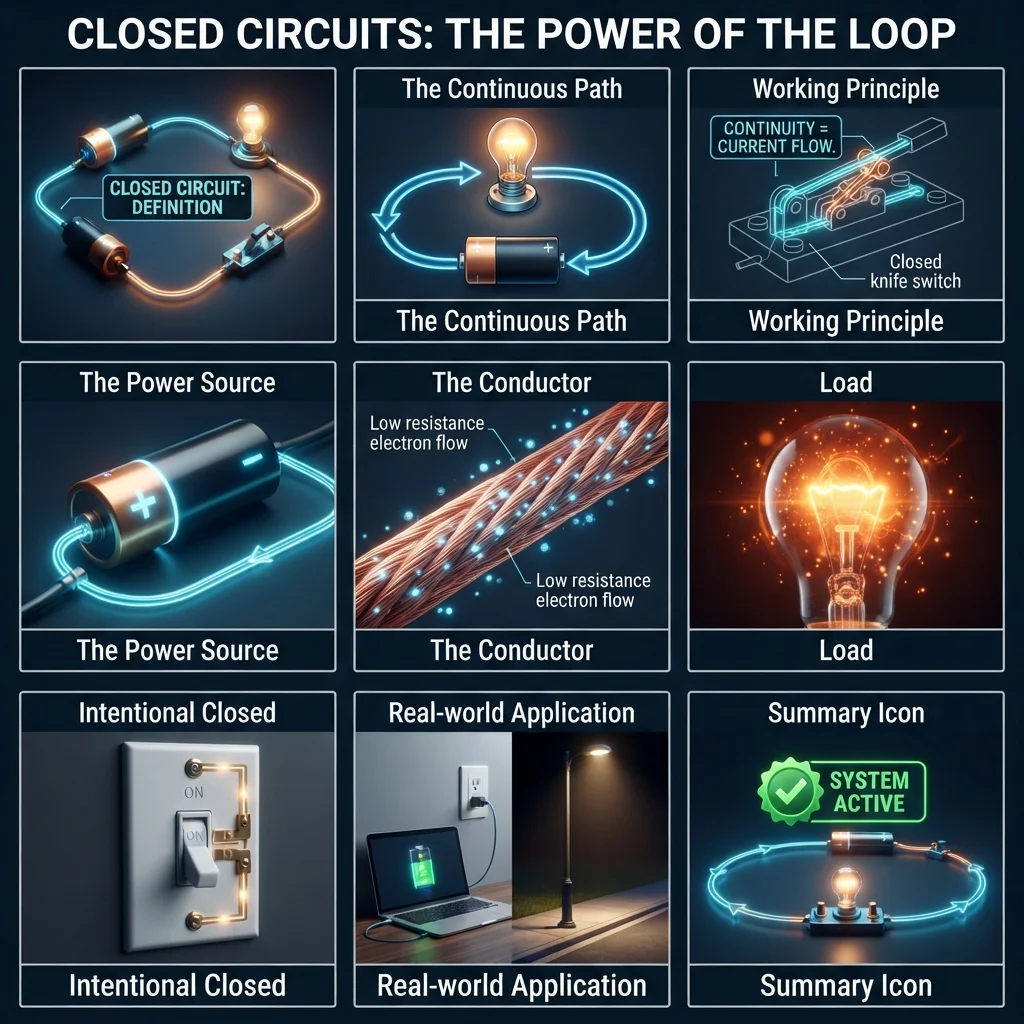
A closed circuit is an electrical circuit with a complete conducting path that allows electric current to flow from the power source through the load and back to the source.
In simple words:
Closed circuit = complete path + current can flow
A circuit normally needs a source, conductors, a load, and a complete electrical path.
For example, consider a simple battery-powered flashlight.
The battery provides voltage, wires carry current, the switch controls the circuit, and the lamp uses electrical energy.
When the switch is turned ON, the contacts close. The electrical path becomes complete, and current flows through the lamp.
The lamp then produces light.
Practical Example
Consider this simple circuit:
Battery → Switch → Lamp → Battery
When the switch is closed:
Battery → Closed Switch → Lamp → Battery
The complete path allows current to flow.
When the switch is opened:
Battery → Open Switch → Lamp → Battery
The path is interrupted, so normal current stops.
This simple example explains the basic Closed Circuit Meaning.
Closed Circuit Working Principle
The closed circuit working principle is based on the idea that electric current needs a continuous conducting path.
Voltage creates the electrical potential difference that drives current, while the circuit provides a path for that current.
Step-by-Step Working
- The power source produces an electrical potential difference.
- Conductors connect the source to the load.
- A switch or control device completes the path.
- The circuit becomes continuous.
- Current flows through the load.
- The load converts electrical energy into another form.
- Current returns through the circuit to the source.
For example, in a simple lamp circuit, electrical energy is converted into light and heat.
Easy Water Analogy
Think of electricity as water moving through a pipe.
A water pump creates pressure, similar to how a voltage source creates electrical potential.
If the pipe forms a complete loop, water can circulate.
If a valve closes or the pipe is broken, the flow stops.
The same basic idea applies to electrical circuits:
- Voltage = electrical pressure
- Current = electrical flow
- Wire = conducting path
- Load = device using energy
- Closed circuit = complete path
This analogy helps beginners understand why current requires a complete circuit.
What Happens When the Circuit Closes?
When a switch closes, the resistance of the switch contacts becomes very low compared with the rest of the circuit.
The circuit now provides a continuous path.
According to Ohm’s law:
I = V / R
where:
- I = current
- V = voltage
- R = resistance
If the circuit has suitable voltage and finite resistance, current can flow.
The actual current depends on the source, load, conductor resistance, and other circuit conditions.
Types / Classification of Closed Circuits
Closed circuits can be classified according to their connection, operation, and control method.
1. Series Closed Circuit
In a series circuit, components are connected one after another in a single current path.
There is only one main path for current.
For example:
Source → Lamp 1 → Lamp 2 → Source
If one component becomes open, the complete circuit path is interrupted.
Series circuits are useful for understanding basic electrical principles and are used in certain control and electronic applications.
2. Parallel Closed Circuit
A parallel circuit has multiple paths for current.
For example, several lamps can be connected across the same supply.
If one lamp fails open, the other branches may continue operating.
Parallel circuits are commonly used in building electrical systems because individual loads can operate independently.
3. Series-Parallel Closed Circuit
A series-parallel circuit combines series and parallel connections.
Some components may be connected in series while other branches operate in parallel.
These circuits are common in practical electrical and electronic systems because real systems often contain several different connection arrangements.
4. DC Closed Circuit
A DC closed circuit operates from a direct-current source.
Examples include:
- Battery circuits
- Control circuits
- Automotive systems
- Electronic devices
- DC motors
Current generally flows in one direction in a simple DC circuit.
5. AC Closed Circuit
An AC closed circuit operates from an alternating-current source.
Examples include:
- Household circuits
- Industrial motors
- Transformers
- AC lighting
- HVAC equipment
In AC circuits, voltage and current change direction periodically.
6. Control Closed Circuit
Control circuits use switches, relays, contactors, sensors, and controllers to control electrical equipment.
For example, a motor starter control circuit may close when a start command is given.
This allows current to energize a contactor coil and operate the motor circuit.
7. Normally Closed Control Circuit
In control systems, a normally closed (NC) contact is closed in its normal state.
When the device is activated, the contact opens.
NC contacts are widely used in:
- Emergency-stop circuits
- Safety interlocks
- Protection systems
- Control circuits
They help systems respond to certain fault or emergency conditions.
Main Components of a Closed Circuit
A closed circuit is made from several important parts.
Power Source
The power source provides electrical energy.
Common examples include:
- Batteries
- Generators
- Power supplies
- Utility electrical systems
Without a suitable source, a closed path alone cannot produce useful current.
Conductors
Conductors provide a low-resistance path for current.
Copper and aluminum are common conductor materials.
The conductor must be properly sized for the expected current and installation conditions.
Load
The load consumes electrical energy.
Examples include:
- Lamps
- Motors
- Heaters
- Fans
- Solenoids
- Electronic equipment
The load converts electrical energy into useful output.
Switch
A switch controls circuit continuity.
When closed, it allows current to flow.
When open, it interrupts the path.
Protective Device
Fuses and circuit breakers protect circuits against excessive current under applicable conditions.
If a protective device operates, it can open the circuit.
Terminals and Connections
Terminals connect wires to electrical equipment.
Loose or damaged terminals can increase resistance, produce heat, or interrupt the circuit.
Control Devices
Modern circuits may use:
- Relays
- Contactors
- Sensors
- PLCs
- Push buttons
- Limit switches
These devices determine when the circuit should be closed or opened.
Advantages of a Closed Circuit
A properly designed closed circuit provides several important benefits.
- Allows current to flow through the intended electrical path.
- Makes electrical equipment operate normally.
- Provides controlled energy transfer from the source to the load.
- Supports automation using switches, relays, sensors, and controllers.
- Allows electrical measurements such as current and voltage under operating conditions.
- Supports efficient power distribution when correctly designed.
- Makes troubleshooting possible because technicians can measure circuit behavior while operating.
Real-World Benefit
A factory motor cannot operate simply because voltage is available at the panel. The required control and power circuits must form the correct complete paths.
This is why understanding circuit continuity is fundamental for industrial troubleshooting.
Disadvantages / Limitations of a Closed Circuit
A closed circuit is necessary for normal operation, but it can also create hazards if it is not properly designed.
Current Can Become Excessive
A closed circuit with a very low unintended resistance can allow extremely high current.
This condition is commonly associated with a short circuit.
Electrical Shock Hazard
An energized closed circuit can expose workers to dangerous voltage and current.
Proper isolation and safety procedures are essential.
Component Heating
Excessive current can heat conductors and components.
Faults Can Spread
A fault in one part of a connected electrical system can affect other equipment if protection is not correctly designed.
Requires Proper Protection
Every practical electrical installation requires suitable protective devices and appropriate conductor sizing.
Troubleshooting Can Be Dangerous
Testing an energized closed circuit requires appropriate instruments, procedures, and training.
Closed Circuit Applications
The Closed Circuit applications are found almost everywhere electricity is used.
Home Applications
Closed circuits are used in:
- Lighting systems
- Ceiling fans
- Refrigerators
- Washing machines
- Air conditioners
- Television systems
- Computers
- Kitchen appliances
When you switch on a light, the switch closes the circuit and allows current to reach the lamp.
Industrial Applications
Industrial systems rely heavily on closed circuits.
Applications include:
- Motor starters
- Pumps
- Compressors
- Conveyor systems
- Control panels
- Machine tools
- Industrial heaters
- Automated production equipment
Automotive Applications
Vehicles contain many electrical circuits.
Examples include:
- Starter circuits
- Lighting
- Horns
- Fuel systems
- Sensors
- Ignition systems
- Electronic control units
Electronics
Electronic devices use many closed current paths.
Examples include:
- Computers
- Mobile devices
- Power supplies
- Audio systems
- Communication equipment
- Control boards
Modern Technology
Closed circuits are also fundamental to:
- Solar power systems
- Battery storage
- Electric vehicles
- Robotics
- Smart homes
- Industrial automation
- Data centers
Difference Between Open Circuit and Closed Circuit
Understanding the difference between open circuit and closed circuit is essential for beginners.
| Feature | Open Circuit | Closed Circuit |
|---|---|---|
| Electrical path | Incomplete | Complete |
| Current | Normally zero | Can flow |
| Resistance | Very high/ideally infinite | Finite |
| Load operation | Normally stops | Can operate |
| Switch example | OFF | ON |
| Main condition | Broken path | Complete path |
Simple Example
Consider a flashlight.
With the switch OFF, the circuit is open and the lamp remains off.
With the switch ON, the circuit becomes closed and current flows through the lamp.
The switch therefore controls whether the circuit is open or closed.
Difference Between Closed Circuit and Short Circuit
These terms are sometimes confused.
A normal closed circuit has a complete path through the intended load.
A short circuit creates an unintended low-resistance path.
| Feature | Closed Circuit | Short Circuit |
|---|---|---|
| Path | Intended complete path | Unintended low-resistance path |
| Load | Normally included | May be bypassed |
| Current | Designed/controlled | Can become extremely high |
| Result | Normal operation | Fault condition |
| Protection | Normal operation | Fuse/breaker may operate |
A closed circuit is a normal operating condition.
A short circuit is generally a fault condition.
Selection Guide
When designing or working with a closed circuit, the goal is not simply to make the circuit complete. The circuit must also be safe and suitable for the load.
Step 1: Identify the Source
Determine:
- AC or DC
- Voltage
- Available current
- Frequency for AC systems
Step 2: Identify the Load
Determine the equipment’s electrical requirements.
Check the manufacturer’s nameplate where applicable.
Step 3: Select the Conductor
Choose a conductor suitable for:
- Load current
- Voltage
- Temperature
- Installation method
- Environmental conditions
Step 4: Select Protection
Use suitable:
- Fuses
- Circuit breakers
- Motor protection
- Ground-fault protection where required
- Other protective devices
Step 5: Check Connections
Make sure terminals are:
- Correctly sized
- Properly tightened
- Clean
- Suitable for the conductor
Step 6: Test Before Operation
Verify continuity and other required electrical conditions using appropriate test equipment.
Beginner Tip
Do not assume that a circuit is safe simply because it is closed.
Always determine whether the circuit is energized and follow proper electrical isolation and testing procedures.
Common Problems & Solutions
Why is my closed circuit not working?
A circuit may appear closed but still fail because of:
- No power supply
- Broken conductor elsewhere
- Faulty switch
- Failed load
- Loose connection
- Open protective device
- Incorrect wiring
Start troubleshooting from the power source and work systematically toward the load.
Can a closed circuit have zero current?
Yes.
A circuit may be physically closed but have no current if there is no voltage source, if the source is disconnected, or if the circuit conditions prevent current flow.
Therefore, “closed” describes the path, not a guaranteed current value.
Why does a breaker trip when I close a circuit?
A breaker may trip because of:
- Short circuit
- Overload
- Ground fault
- Equipment fault
- Incorrect breaker application
Do not repeatedly reset a breaker without finding the cause.
What is a normally closed circuit?
In control terminology, a normally closed contact is closed in its normal state and opens when actuated.
It is commonly used for safety and control functions.
How do I test circuit continuity?
A continuity test is normally performed on a de-energized circuit with suitable test equipment.
Never use a continuity function on an energized circuit unless the instrument and procedure specifically allow it.
Why is a closed circuit drawing too much current?
Possible reasons include:
- Overloaded equipment
- Short circuit
- Low load resistance
- Incorrect voltage
- Motor mechanical problems
- Faulty components
Measure current and investigate the circuit systematically.
Can a closed circuit overheat?
Yes.
Excessive current, poor connections, undersized conductors, or faulty components can produce excessive heat.
Does every closed circuit have a switch?
No.
A circuit can be closed without a manually operated switch.
For example, some electronic circuits remain continuously connected while control devices change their operation.
Future Trends in Closed Circuit Technology
Electrical systems are becoming more automated and intelligent.
Smart Controls
Smart switches and controllers can open and close circuits based on:
- Motion
- Temperature
- Time
- Light level
- Remote commands
Industrial Automation
PLCs and intelligent control systems can monitor circuit states and control machinery automatically.
Smart Buildings
Modern buildings use automated systems to control lighting, HVAC equipment, security systems, and energy consumption.
Electric Vehicles
EVs contain sophisticated electrical and electronic circuits that manage batteries, motors, charging, and safety systems.
Renewable Energy
Solar and battery systems use power electronic circuits to control energy conversion and distribution.
Digital Diagnostics
Modern electrical equipment can continuously monitor voltage, current, temperature, and circuit status.
This allows technicians to detect abnormal conditions earlier and improve preventive maintenance.
Conclusion
Understanding Closed Circuit Meaning is one of the first and most important steps in learning electrical engineering. A closed circuit provides a complete conducting path, allowing current to flow from the source through the intended load and back to the source.
Closed circuits are found in household wiring, industrial control systems, motors, vehicles, electronics, automation, renewable-energy systems, and modern smart technology. They can be simple, such as a battery and lamp, or highly complex, such as an automated industrial control system.
The most important lesson is that a closed path does not automatically mean a circuit is safe. Proper voltage, current, conductor sizing, protection, and connections must all be considered.
Once you understand the relationship between open and closed circuits, many electrical troubleshooting and circuit-analysis concepts become much easier to learn.