
Imagine a technician needs to repair a large electrical motor inside a factory. Before touching the motor, the technician must make sure the electrical supply is completely disconnected. Simply switching off a control button is not enough because the circuit may still be electrically energized. This is where an isolator becomes important.
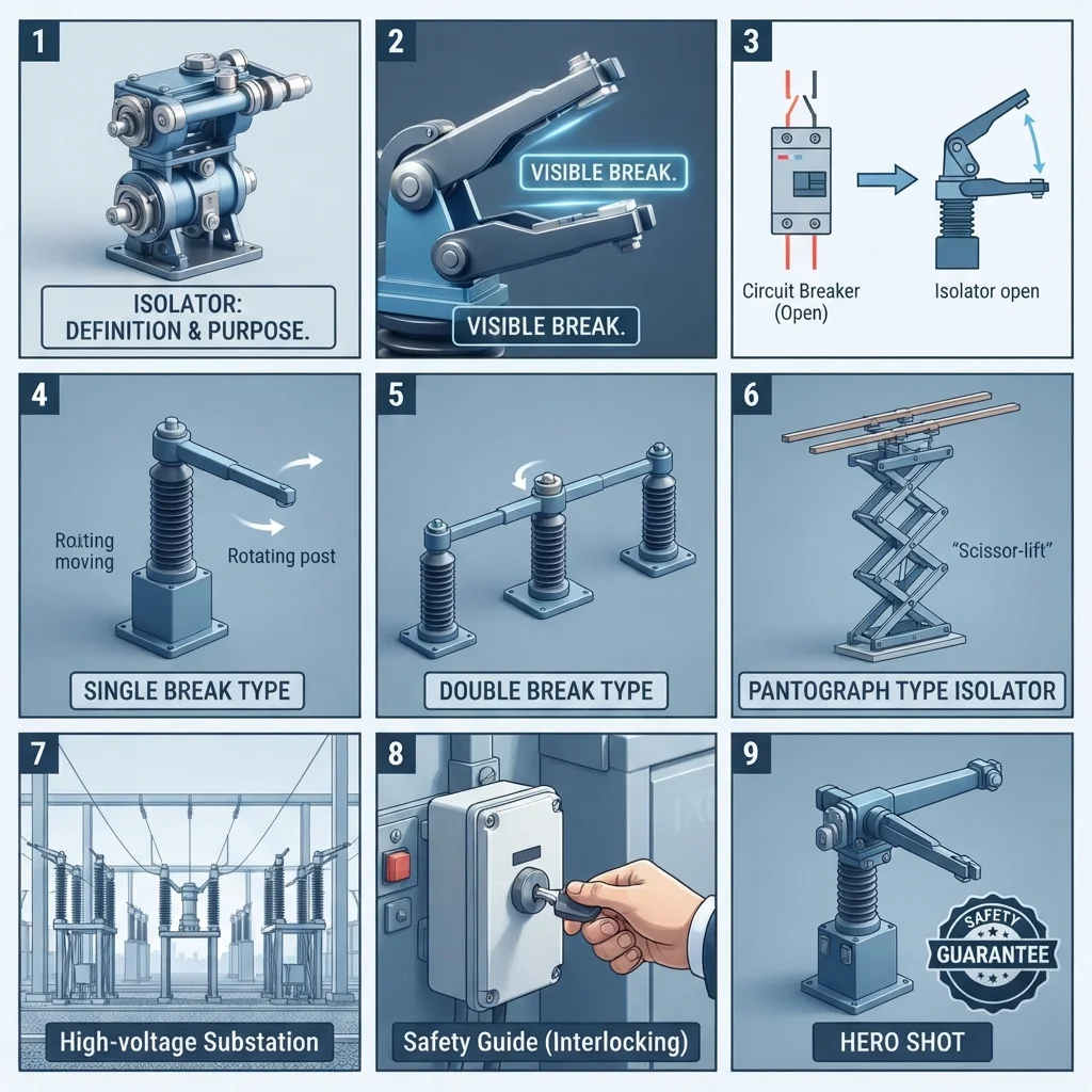
An isolator is a mechanical switching device used to disconnect electrical equipment or a section of an electrical system from its power source. It provides a visible and reliable separation so technicians can work safely during maintenance.
Understanding isolator meaning is important for electrical students, engineers, electricians, and maintenance technicians because isolation is a basic part of electrical safety. An isolator is commonly found in distribution boards, substations, industrial plants, transformers, motors, and many other electrical installations.
In this guide, you will learn what an isolator is, how an isolator works, its different types, main components, advantages and disadvantages, applications, selection methods, common problems, and future developments.
What Is an Isolator?
An isolator is an electrical switching device designed to disconnect a circuit, electrical equipment, or installation from its power supply for safe maintenance and inspection.
In simple words, an isolator works like a physical separation switch. When it is opened, it creates a clear gap between the electrical supply and the equipment being isolated.
Unlike a circuit breaker, an isolator is generally not designed to interrupt a large load current or clear a short circuit. It is normally operated when the circuit is already de-energized or the load has been safely removed.
Simple Example
Consider an industrial motor connected to a three-phase supply.
A technician wants to repair the motor. The basic process may be:
- Stop the motor using the normal control system.
- Switch off the appropriate protective device.
- Open the isolator.
- Verify that the equipment is de-energized.
- Apply the required lockout/tagout procedure.
- Perform the maintenance work.
The isolator provides a clear physical disconnection point.
Isolator Meaning in Simple Words
An isolator means:
A device used to safely disconnect electrical equipment from its power source so maintenance can be performed.
The exact operating procedure depends on the equipment, system design, and applicable electrical safety rules.
Isolator Working Principle
The isolator working principle is based on physically separating electrical contacts.
When the isolator is closed, its contacts touch each other and provide a continuous electrical path.
When the isolator is opened, the contacts move apart and create an air gap or another approved insulating separation.
Step-by-Step Working
1. Supply Is Connected
When the isolator is in the ON or closed position, electrical contacts are physically connected.
Current can flow from the source toward the connected equipment.
2. Equipment Is Switched Off
Before opening an isolator, the load is normally switched off using an appropriate switching or protective device.
This reduces the risk of opening the isolator while carrying load current.
3. Isolator Is Opened
The operating handle moves the contacts apart.
The electrical connection between the source and the isolated equipment is broken.
4. Physical Isolation Is Created
A visible or clearly established separation is provided between the contacts.
This separation helps confirm that the equipment has been disconnected.
5. Maintenance Can Begin After Verification
The technician must still verify the absence of voltage using an appropriate test method.
Opening an isolator alone should never replace proper electrical safety procedures.
Easy Analogy
Think of an isolator like a water valve.
If the valve is closed, water cannot flow into the pipe section beyond it.
Similarly, when an electrical isolator is opened, the electrical connection to the isolated section is physically separated.
However, electricity requires additional safety checks because an isolated circuit can still contain stored energy or receive voltage from another source.
Types of Isolators
Isolators can be classified according to their number of poles, construction, installation method, and application.
1. Single-Pole Isolator
A single-pole isolator disconnects one conductor.
It is used in suitable single-phase applications where the system design allows isolation of one conductor.
Its use must follow the wiring system and applicable electrical requirements.
2. Double-Pole Isolator
A double-pole isolator disconnects two conductors at the same time.
It is commonly used in single-phase systems where both line and neutral need to be disconnected for maintenance.
Double-pole isolation can provide a stronger level of separation than switching only the line conductor.
3. Triple-Pole Isolator
A triple-pole isolator is designed to disconnect three conductors simultaneously.
It is commonly associated with three-phase electrical systems.
For example, a three-phase motor may use a suitable three-pole isolation device.
4. Four-Pole Isolator
A four-pole isolator can disconnect three phases and the neutral conductor.
It may be used where the system design requires neutral isolation along with the phase conductors.
The decision to switch the neutral depends on the electrical system and applicable standards.
5. Fuse-Switch Isolator
A fuse-switch isolator combines switching and fuse protection in one arrangement.
The fuse provides overcurrent protection while the switching mechanism provides isolation.
These devices are commonly found in industrial distribution systems.
6. Load-Break Isolator
A load-break switch is specifically designed to interrupt current under defined load conditions.
It should not automatically be treated as the same thing as a basic isolator.
The manufacturer’s rating and operating instructions must be followed.
7. Outdoor Isolator
Outdoor isolators are designed for external installations.
They normally require suitable protection against weather, dust, moisture, corrosion, and mechanical damage.
Outdoor isolators are commonly used near motors, pumps, air-conditioning equipment, and industrial machinery.
8. Indoor Isolator
Indoor isolators are designed for protected electrical environments.
They may be installed inside distribution boards, electrical rooms, control panels, and other protected areas.
The enclosure rating must match the installation environment.
Main Components of an Isolator
Although isolators can have different designs, several important components are common.
1. Fixed Contacts
Fixed contacts provide the stationary electrical connection.
When the isolator is closed, the moving contacts make contact with these fixed parts.
2. Moving Contacts
Moving contacts physically move away from or toward the fixed contacts.
Their movement creates or removes the electrical connection.
3. Operating Handle
The handle allows an operator to open or close the isolator.
It should provide a clear indication of the switch position.
4. Insulating Material
Insulating materials electrically separate live components from the enclosure and operating mechanism.
Good insulation is essential for safe operation.
5. Enclosure
The enclosure protects internal components from accidental contact and environmental conditions.
The required enclosure type depends on where the isolator is installed.
6. Terminals
Terminals provide connection points for incoming and outgoing conductors.
They must be suitable for the conductor size and type specified by the manufacturer.
7. Locking Mechanism
Many isolators provide a facility for locking the device in the OFF position.
This is especially useful during maintenance and lockout/tagout procedures.
Advantages of an Isolator
The main isolator advantages and disadvantages should be understood before selecting or using one.
Advantages
- Provides physical electrical isolation.
- Improves maintenance safety.
- Makes the disconnected condition easier to identify.
- Helps prevent accidental energization.
- Can be locked in the OFF position on suitable designs.
- Provides a dedicated isolation point.
- Simple mechanical construction.
- Useful for local equipment isolation.
- Available in many pole configurations.
- Can be used in residential, commercial, and industrial systems.
One major benefit is that an isolator provides a clear separation rather than relying only on a control signal.
Disadvantages and Limitations
An isolator also has important limitations.
- A basic isolator is generally not intended to interrupt high load current.
- It does not normally provide short-circuit protection.
- It does not replace a circuit breaker or fuse.
- Incorrect operation can create dangerous arcing.
- Contacts can wear over time.
- Poor installation can cause overheating.
- Environmental exposure can damage unsuitable isolators.
- It does not automatically prove that a circuit is dead.
- Stored electrical energy may remain in some equipment.
- Back-feed from another source can create a serious hazard.
For these reasons, technicians should follow the correct isolation procedure rather than simply opening a switch and starting work.
Applications of Isolators
The isolator applications range from small electrical installations to large industrial power systems.
Home Applications
Suitable isolation switches may be used for:
- Air-conditioning units
- Water heaters
- Pumps
- Electric ovens
- Distribution equipment
- Outdoor electrical equipment
A local isolation switch allows maintenance personnel to disconnect equipment from its supply.
Commercial Buildings
Commercial buildings use isolation devices for:
- HVAC equipment
- Pumps
- Elevators and associated equipment
- Lighting systems
- Electrical distribution
- Mechanical equipment
- Building services
Local isolation can make maintenance easier and safer.
Industrial Applications
Industrial facilities commonly use isolators around:
- Electric motors
- Pumps
- Compressors
- Conveyors
- Transformers
- Generators
- Control panels
- Machine tools
- Industrial fans
For example, an isolator installed near a motor allows maintenance personnel to disconnect the motor locally.
Electrical Substations
High-voltage systems use specialized isolation equipment to separate parts of a power network.
Substation isolators may be used to isolate:
- Transformers
- Busbars
- Transmission lines
- Circuit breakers
- Other high-voltage equipment
High-voltage isolation requires strict procedures and appropriately rated equipment.
Renewable Energy Systems
Modern solar installations can include DC and AC isolation devices.
They may be used to isolate:
- Solar PV arrays
- Inverters
- Battery systems
- AC distribution equipment
The isolator must be specifically rated for the voltage, current, and type of circuit.
Isolator vs Circuit Breaker
One of the most common questions is the difference between isolator and circuit breaker.
| Feature | Isolator | Circuit Breaker |
|---|---|---|
| Main purpose | Isolation | Protection and switching |
| Physical separation | Yes | Yes |
| Overcurrent protection | Usually no | Yes |
| Short-circuit protection | No | Yes |
| Normal load interruption | Usually not for basic isolators | Yes, within rating |
| Automatic operation | Usually no | Yes |
| Maintenance isolation | Excellent | Can be used, but isolation requirements depend on system |
| Arc interruption capability | Limited by design | Designed for interruption |
| Typical use | Safe maintenance isolation | Fault protection and switching |
The important point is that an isolator and circuit breaker perform different jobs.
A circuit breaker protects a circuit from abnormal current conditions. An isolator provides a safe means of separation.
In many installations, both devices are used together.
Isolator vs Switch
An isolator and an ordinary switch may look similar, but their purposes can differ.
A normal switch is commonly designed for controlling electrical loads.
An isolator is primarily intended to provide safe electrical separation.
Some modern devices combine switching and isolation functions, but their exact capabilities must be confirmed from the equipment rating and manufacturer’s documentation.
How to Select the Right Isolator
Choosing the correct isolator requires more than checking the voltage rating.
1. Check System Voltage
Select an isolator rated for the actual system voltage.
Never use a device below the required voltage rating.
2. Check Current Rating
The isolator must be suitable for the current and intended duty of the circuit.
Consider the continuous operating current and installation conditions.
3. Determine the Number of Poles
Choose the appropriate configuration:
- Single pole
- Double pole
- Three pole
- Four pole
The required arrangement depends on the electrical system.
4. Check AC or DC Application
AC and DC isolation requirements are not always the same.
DC circuits can be particularly demanding because an arc may be harder to extinguish.
Always verify that the device is specifically rated for the circuit type.
5. Consider the Environment
For outdoor, dusty, wet, or corrosive locations, select an enclosure and device suitable for the environment.
6. Check Short-Circuit Conditions
An isolator does not normally provide short-circuit protection.
The upstream protective device must be coordinated with the isolation equipment.
7. Consider Lockout Requirements
For maintenance applications, choose a design that supports the required lockout/tagout procedure.
Beginner Tip
Never select an isolator only because it physically fits the panel.
Always check:
Voltage + current + poles + AC/DC rating + enclosure + installation conditions + applicable standards.
Common Problems and Solutions
Why Does an Isolator Become Hot?
A hot isolator can indicate:
- Loose terminals
- Poor contact pressure
- Overloaded circuit
- Damaged contacts
- Incorrect conductor size
- Poor installation
The circuit should be safely isolated and inspected by a qualified person.
Why Does the Isolator Spark?
Sparking can occur if the device is operated while carrying a load beyond its intended capability or if contacts are damaged.
Do not continue operating a device that shows abnormal arcing.
Can an Isolator Protect Against a Short Circuit?
No. A basic isolator is not a short-circuit protection device.
A suitable fuse or circuit breaker is normally required for protection.
Can an Isolator Be Used as an Emergency Switch?
Not automatically.
Emergency switching has specific design and performance requirements. A standard isolator should not be assumed to meet them.
Why Is the Isolator Not Supplying Power?
Possible causes include:
- Upstream breaker is OFF.
- Fuse is open.
- Loose connection exists.
- Contacts are damaged.
- Incorrect wiring exists.
- Another protective device has operated.
Testing should be performed using appropriate electrical safety procedures.
Does Opening an Isolator Mean the Circuit Is Safe?
Not by itself.
A safe isolation procedure normally includes identifying the correct circuit, disconnecting it, preventing reconnection, verifying absence of voltage, and addressing stored or alternative sources of energy.
Future Trends in Isolator Technology
Electrical isolation technology is developing as electrical systems become more automated and connected.
Modern installations increasingly combine traditional isolation with improved safety features.
Smart Monitoring
Some electrical systems can monitor switch position and provide status information to control systems.
This can help operators identify whether equipment is connected or isolated.
Remote Status Indication
Remote indication can allow control-room personnel to see the status of field equipment.
However, remote indication should not replace physical verification where safety procedures require it.
Renewable Energy Isolation
Solar PV, battery storage, and electric vehicle infrastructure are creating new isolation requirements.
Specialized DC isolation equipment is becoming increasingly important.
Improved Enclosures
Manufacturers continue to develop stronger enclosures for outdoor, dusty, wet, and corrosive environments.
Better Maintenance Features
Lockable handles, position indicators, and improved terminal designs help make maintenance safer and easier.
The future direction is toward isolation devices that combine reliable mechanical separation with better monitoring and system integration.
Conclusion
Understanding isolator meaning is essential for anyone working with electrical systems. An isolator is primarily used to physically disconnect electrical equipment from its power source so that inspection, repair, and maintenance can be performed safely.
The isolator working principle is simple: electrical contacts are physically separated to create a reliable isolation point. However, an isolator is not normally a replacement for a circuit breaker because it does not provide the same overcurrent and short-circuit protection.
The right isolator depends on voltage, current, number of poles, AC or DC operation, environment, and installation requirements. Proper isolation procedures are equally important. By understanding isolator types, components, applications, and limitations, electrical professionals can make safer and better decisions in real-world installations.