
When you switch on a camera flash, you often notice a small delay before it fires. That delay happens because the capacitor inside the circuit is charging. Similarly, in electric vehicles, power supplies, and electronic devices, capacitors are constantly charging and discharging to regulate energy flow.
Understanding the Capacitor Charging Equation is essential for anyone working in electrical or electronics engineering. It helps explain how voltage builds up across a capacitor over time when connected to a power source. Without this knowledge, designing timing circuits, filters, and energy storage systems becomes difficult.
This topic is especially important for students, technicians, and engineers because it forms the foundation of transient analysis in circuits. It also connects directly with real-world systems like RC circuits, signal processing, and power electronics.
In this article, you will learn:
- What capacitor charging means in simple terms
- The capacitor charging equation and how it works
- Step-by-step working principle
- Types of charging behavior
- Real-world applications and troubleshooting
- Advantages, limitations, and future trends
By the end, you will clearly understand how capacitors charge in practical electrical systems.
What Is the Capacitor Charging Equation?
The Capacitor Charging Equation is a mathematical formula that describes how the voltage across a capacitor increases over time when it is connected to a DC voltage source through a resistor in an RC (Resistor-Capacitor) circuit.
When a capacitor is first connected to a power supply, it does not charge instantly. Instead, it stores electrical energy gradually. The charging speed depends on the values of the resistance (R) and capacitance (C) in the circuit. The capacitor voltage starts at 0 volts and slowly rises until it becomes equal to the supply voltage.
The capacitor charging equation helps students, engineers, and technicians predict the capacitor voltage at any moment during the charging process. It is widely used in electronics, electrical engineering, automation systems, communication circuits, and timing applications.
Capacitor Charging Voltage Equation
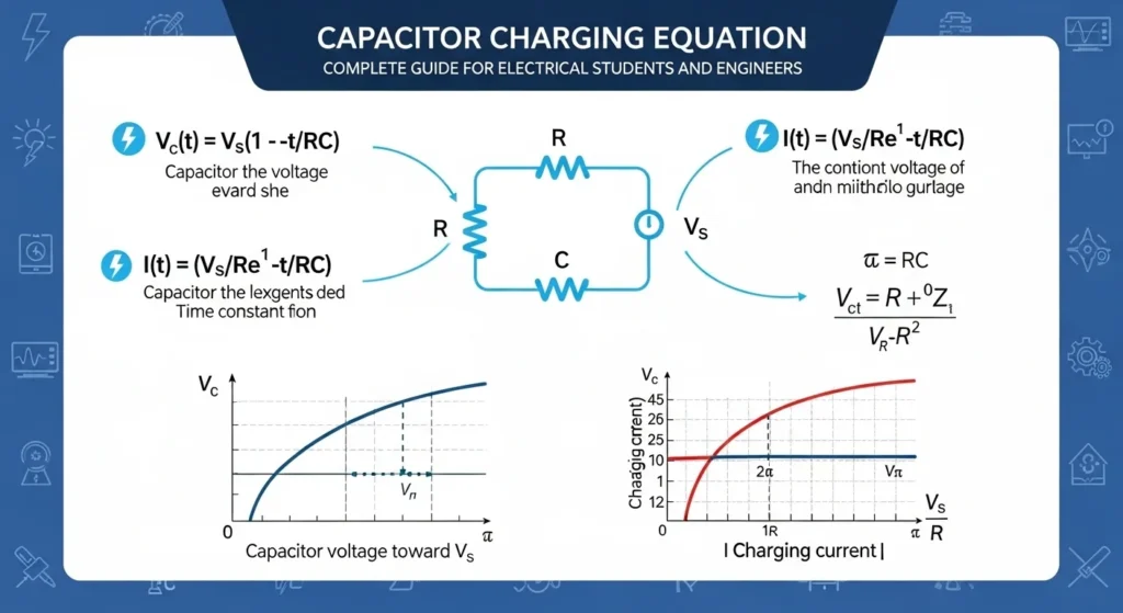
The standard equation for the voltage across a charging capacitor is:
[
V_C(t)=V_S\left(1-e^{-\frac{t}{RC}}\right)
]
Explanation of the Formula
Each symbol in the capacitor charging equation has a specific meaning.
Where:
- (V_C(t)) = Voltage across the capacitor at time t (Volts)
- (V_S) = Supply voltage applied to the circuit (Volts)
- R = Resistance in the circuit (Ohms, Ω)
- C = Capacitance of the capacitor (Farads, F)
- t = Time after charging begins (Seconds, s)
- RC (τ) = Time Constant of the circuit
- e = Euler’s constant (approximately 2.718)
The time constant (τ = RC) determines how quickly the capacitor charges. A larger resistance or capacitance results in a slower charging process, while smaller values allow the capacitor to charge more quickly.
Standard Capacitor Charging Current Equation
The charging current decreases as the capacitor stores more electrical energy.
The current during charging is given by:
[
I(t)=\frac{V_S}{R}e^{-\frac{t}{RC}}
]
Where:
- (I(t)) = Charging current at time t (Amperes)
- (V_S) = Supply voltage (Volts)
- R = Resistance (Ohms)
- t = Time (Seconds)
- RC = Time constant
At the beginning of the charging process, the current is at its maximum value. As the capacitor charges, the current gradually decreases until it becomes almost zero.
How the Capacitor Charging Equation Works
The charging process can be understood in a few simple steps.
Step 1: The Circuit Is Connected
A DC voltage source is connected to an RC circuit containing a resistor and an uncharged capacitor.
At this moment:
- Capacitor Voltage = 0 V
- Charging Current = Maximum
Step 2: The Capacitor Begins Charging
Current starts flowing through the resistor and into the capacitor.
The capacitor stores electrical energy in the form of an electric field.
Its voltage begins to rise gradually.
Step 3: Charging Current Decreases
As the capacitor voltage increases, the difference between the supply voltage and capacitor voltage becomes smaller.
Because of this, the charging current gradually decreases.
Step 4: Capacitor Voltage Continues Increasing
The capacitor continues storing energy.
Its voltage follows an exponential curve rather than increasing at a constant rate.
Step 5: Fully Charged Condition
After approximately five time constants (5τ), the capacitor is considered fully charged.
At this point:
- Capacitor Voltage ≈ Supply Voltage
- Charging Current ≈ 0 A
The capacitor behaves like an open circuit in a DC circuit because no further current flows through it.
Practical Example
Suppose a capacitor is connected to a 10 V DC supply through a resistor.
Initial Condition (t = 0)
- Supply Voltage = 10 V
- Capacitor Voltage = 0 V
- Charging Current = Maximum
The capacitor is completely uncharged.
During Charging
As time passes:
- The capacitor stores electrical energy.
- The capacitor voltage gradually increases.
- The charging current continuously decreases.
For example:
- After a short time, the capacitor voltage may reach 4 V.
- Later, it may increase to 7 V.
- Eventually, it approaches 10 V.
Final Condition
After sufficient time (approximately 5RC):
- Capacitor Voltage ≈ 10 V
- Charging Current ≈ 0 A
The capacitor is now fully charged and no longer draws current from the DC source.
Simple Explanation
Imagine filling an empty water tank using a pipe.
- The battery is like the water pump.
- The capacitor is like the empty water tank.
- The resistor is like a valve that controls the water flow.
At first, the tank fills quickly because it is empty.
As the water level rises, the filling rate slows down.
Eventually, the tank becomes full, and no more water enters.
A capacitor charges in exactly the same way. It charges rapidly at first, then more slowly, until its voltage becomes equal to the supply voltage.
This gradual increase in voltage is precisely what the Capacitor Charging Equation describes.
Capacitor Charging Working Principle
The Capacitor Charging Working Principle is based on the gradual accumulation of electric charge on the two conductive plates of a capacitor when it is connected to a DC voltage source through a resistor. Unlike a battery, a capacitor does not produce electrical energy; instead, it stores energy in the form of an electric field between its plates.
When the circuit is first energized, the capacitor is completely uncharged, so current flows freely through the resistor into the capacitor. As electric charge accumulates on the capacitor plates, the voltage across the capacitor gradually increases while the charging current continuously decreases. Eventually, the capacitor becomes fully charged, and the current stops flowing.
The charging process follows an exponential curve, which is mathematically described by the Capacitor Charging Equation. The speed of charging depends on the RC time constant (τ = R × C). A larger resistor or capacitor causes slower charging, while smaller values allow the capacitor to charge more quickly.
Step-by-Step Capacitor Charging Process
The charging process of a capacitor can be understood in the following simple steps.
Step 1: The Circuit Is Switched ON
When the switch is closed, the DC power supply is connected to the resistor and capacitor.
At this moment:
- The capacitor is completely discharged.
- Capacitor voltage is 0 volts.
- Charging current is at its maximum value.
Since there is no stored charge, the capacitor initially behaves like a short circuit.
Step 2: Current Begins Flowing
Electric current starts flowing from the voltage source through the resistor and into the capacitor.
Electrons begin accumulating on one capacitor plate, while an equal number of electrons leave the opposite plate.
This creates an electric field between the two plates.
Step 3: The Capacitor Starts Storing Charge
As more electric charge collects on the capacitor plates, the capacitor begins storing electrical energy.
During this stage:
- Stored charge increases.
- Capacitor voltage starts increasing.
- Charging current begins decreasing.
The resistor controls the charging rate by limiting the current flowing into the capacitor.
Step 4: Capacitor Voltage Gradually Increases
The voltage across the capacitor does not increase instantly.
Instead, it rises gradually according to the capacitor charging equation.
Initially, the voltage increases rapidly, but as the capacitor stores more charge, the rate of increase becomes slower.
This gradual increase produces the familiar exponential charging curve.
Step 5: Charging Current Continuously Decreases
As the capacitor voltage approaches the supply voltage, the difference between the source voltage and capacitor voltage becomes smaller.
Because of this reduced voltage difference:
- Less current flows through the resistor.
- The charging process slows down.
- Current gradually approaches zero.
This is why the charging current decreases exponentially with time.
Step 6: The Capacitor Becomes Fully Charged
After approximately five time constants (5τ), the capacitor is considered fully charged.
At this point:
- Capacitor voltage is nearly equal to the supply voltage.
- Charging current becomes almost zero.
- No additional charge enters the capacitor.
The capacitor now behaves like an open circuit in a DC circuit because current can no longer flow through it.
How the RC Time Constant Affects Charging
The RC Time Constant (τ = R × C) determines how quickly a capacitor charges.
If Resistance (R) Increases
- Charging becomes slower.
- Current decreases more gradually.
- The capacitor takes longer to reach full voltage.
If Capacitance (C) Increases
- The capacitor stores more charge.
- More time is required for complete charging.
- The charging process becomes slower.
If Both Resistance and Capacitance Are Small
- Charging occurs much faster.
- The capacitor reaches the supply voltage more quickly.
- The current decreases rapidly.
Key Characteristics of Capacitor Charging
During the charging process:
- The capacitor starts with zero voltage.
- Charging current is maximum at the beginning.
- Current continuously decreases over time.
- Capacitor voltage continuously increases.
- The charging curve is exponential rather than linear.
- The resistor limits the charging current.
- The capacitor stores electrical energy in an electric field.
- After approximately 5RC, the capacitor is considered fully charged.
Simple Analogy
Imagine filling an empty water tank through a narrow pipe.
- The battery is like a water pump.
- The resistor is like a valve that controls the water flow.
- The capacitor is like the water tank.
At the Beginning
The tank is empty, so water flows into it very quickly.
This is similar to a capacitor drawing maximum charging current.
As the Tank Fills
The water level rises, reducing the filling speed.
Likewise, as the capacitor stores more charge, the charging current gradually decreases while the capacitor voltage increases.
When the Tank Is Full
The water can no longer enter the tank, so the flow stops.
Similarly, when the capacitor reaches the supply voltage, it becomes fully charged and the charging current becomes almost zero.
Important Points to Remember
- A capacitor charges gradually, not instantly.
- Charging starts with maximum current.
- Capacitor voltage increases exponentially.
- Charging current decreases exponentially.
- The resistor controls the charging speed.
- The RC time constant (τ = R × C) determines how fast the capacitor charges.
- After about 5τ, the capacitor is practically fully charged.
- In a DC circuit, a fully charged capacitor behaves like an open circuit.
Understanding the Capacitor Charging Working Principle is essential for analyzing RC circuits, designing timing circuits, power supplies, filters, and many other electronic and electrical systems. It provides the foundation for understanding how capacitors store and release electrical energy in practical applications.
Types and Classification of Capacitor Charging Behavior
The charging behavior of a capacitor depends on the type of electrical circuit and the components connected to it. In theory, a capacitor can charge instantly, but in practical electrical and electronic circuits, the charging process is always affected by resistance and other circuit elements.
Understanding the different types of capacitor charging behavior helps students, engineers, and technicians analyze RC circuits, design timing circuits, and troubleshoot electronic systems more effectively.
The charging behavior can generally be classified into the following types.
1. Ideal Capacitor Charging (Theoretical Charging)
Ideal capacitor charging is a theoretical concept used to explain the basic principles of capacitor operation.
In an ideal circuit, there is no resistance between the voltage source and the capacitor. Because there is nothing to limit the flow of current, the capacitor is assumed to charge instantly to the supply voltage.
In reality, this condition does not exist because every electrical circuit contains some resistance, even if it is very small.
Characteristics
- No resistance in the circuit
- Instantaneous charging
- Infinite charging current (theoretical)
- Capacitor immediately reaches supply voltage
- Used only for mathematical analysis and basic electrical theory
Applications
- Classroom learning
- Electrical theory
- Circuit analysis
- Basic electronics education
2. RC Circuit Charging (Practical Charging)
RC circuit charging is the most common and practical type of capacitor charging found in real electrical and electronic systems.
In this circuit, a resistor is connected in series with the capacitor. The resistor limits the charging current, causing the capacitor voltage to increase gradually instead of instantly.
The charging process follows an exponential curve, which is described by the Capacitor Charging Equation.
Characteristics
- Includes both a resistor (R) and capacitor (C)
- Charging current is initially maximum
- Capacitor voltage increases gradually
- Charging current decreases continuously
- Charging speed depends on the RC time constant (τ = RC)
- Capacitor becomes nearly fully charged after about 5τ
Applications
- Timing circuits
- Delay circuits
- Power supply filters
- Signal processing
- Motor control circuits
- Industrial automation
- Electronic control systems
This is the most widely used charging method in practical electronics and electrical engineering.
3. Non-Linear Capacitor Charging
Non-linear charging occurs when the charging process is influenced by components whose electrical characteristics change during operation.
Unlike a simple RC circuit, the charging rate does not follow a perfect exponential curve because additional electronic components affect the current and voltage.
Examples include circuits containing:
- Diodes
- Transistors
- MOSFETs
- Integrated Circuits (ICs)
- Operational Amplifiers (Op-Amps)
These components introduce non-linear behavior that changes the charging characteristics of the capacitor.
Characteristics
- Charging rate changes continuously
- Influenced by semiconductor devices
- More complex mathematical analysis
- Does not always follow a simple exponential curve
- Used in advanced electronic circuits
Applications
- Switching power supplies
- Pulse-width modulation (PWM) circuits
- Digital electronics
- Communication systems
- Power electronics
- Microcontroller circuits
- Battery management systems
4. Constant Current Charging
In constant current charging, the capacitor is charged using a fixed current source instead of a fixed voltage source.
Since the charging current remains constant, the capacitor voltage increases almost linearly with time rather than following an exponential curve.
Characteristics
- Constant charging current
- Nearly linear voltage increase
- Controlled charging process
- High charging accuracy
- Suitable for precision electronic circuits
Applications
- Battery charging circuits
- Precision timing circuits
- Analog electronics
- Laboratory instruments
- Medical electronic equipment
Comparison of Capacitor Charging Types
| Charging Type | Circuit Condition | Charging Speed | Voltage Curve | Common Applications |
|---|---|---|---|---|
| Ideal Charging | No resistance | Instant (theoretical) | Instant rise | Electrical theory and education |
| RC Circuit Charging | Resistor and capacitor | Gradual | Exponential | Most practical electrical and electronic circuits |
| Non-Linear Charging | Semiconductor-based circuits | Variable | Non-linear | Advanced electronics and power systems |
| Constant Current Charging | Constant current source | Controlled | Nearly linear | Precision electronics and battery charging |
Which Charging Behavior Is Most Common?
Among all charging methods, RC Circuit Charging is the most common in real-world electrical and electronic systems because every practical circuit contains some resistance. The resistor safely limits the charging current, protects circuit components, and produces the predictable exponential charging behavior described by the Capacitor Charging Equation.
Understanding these different types of capacitor charging behavior helps engineers, technicians, and students design safer, more efficient, and more reliable electrical and electronic circuits.
Main Components of a Capacitor Charging Circuit
A capacitor charging circuit consists of several essential components that work together to store electrical energy safely and efficiently. Each component performs a specific function during the charging process. Understanding these components helps students and engineers analyze RC circuits and apply the Capacitor Charging Equation correctly.
1. Voltage Source (Vs)
The voltage source supplies the electrical energy required to charge the capacitor. It creates the potential difference that forces current to flow through the circuit.
In most capacitor charging circuits, the voltage source is a DC (Direct Current) power supply, such as a battery or DC adapter.
Functions
- Supplies electrical energy to the circuit
- Provides the charging voltage
- Creates the electric field required for current flow
- Determines the maximum voltage the capacitor can reach
Common Voltage Sources
- Batteries
- DC power supplies
- Solar panels
- DC generators
- Adapter power supplies
2. Resistor (R)
The resistor is connected in series with the capacitor to control the charging current. Without a resistor, the capacitor would draw a very large current when first connected to the power source, which could damage the capacitor or other circuit components.
The resistor also determines how quickly the capacitor charges by controlling the RC time constant (τ = RC).
Functions
- Limits the charging current
- Controls charging speed
- Protects the capacitor from excessive current
- Determines the RC time constant
- Improves circuit safety and reliability
Effect of Resistance
- Higher resistance → Slower charging
- Lower resistance → Faster charging
3. Capacitor (C)
The capacitor is the main energy storage component in the circuit. It stores electrical energy in the form of an electric field between its two conductive plates separated by a dielectric material.
As charging continues, the voltage across the capacitor gradually increases until it becomes nearly equal to the supply voltage.
Functions
- Stores electrical energy
- Builds an electric field between its plates
- Increases voltage gradually during charging
- Releases stored energy when required
- Supports timing and filtering applications
Common Capacitor Types
- Ceramic capacitor
- Electrolytic capacitor
- Film capacitor
- Tantalum capacitor
- Supercapacitor
4. Switch
The switch controls when the charging process begins and ends.
Closing the switch completes the circuit, allowing current to flow and the capacitor to charge. Opening the switch disconnects the power source and stops the charging process.
Functions
- Starts the charging process
- Stops current flow when opened
- Controls circuit operation
- Allows safe testing and maintenance
Common Types
- Push-button switch
- Toggle switch
- Relay contact
- Electronic switch (Transistor or MOSFET)
5. Connecting Wires
Connecting wires provide the electrical path between all circuit components.
Good-quality conductors help reduce unnecessary resistance and improve circuit efficiency.
Functions
- Connect circuit components
- Carry charging current
- Complete the electrical circuit
- Minimize power loss
Component Summary Table
| Component | Purpose | Function in Charging Circuit |
|---|---|---|
| Voltage Source (Vs) | Supplies electrical energy | Provides charging voltage |
| Resistor (R) | Controls current | Limits charging current and controls charging speed |
| Capacitor (C) | Stores energy | Stores electrical charge and builds voltage |
| Switch | Controls operation | Starts and stops the charging process |
| Connecting Wires | Connect components | Provide a path for current flow |
Advantages of Capacitor Charging
The capacitor charging process offers several important advantages in electrical and electronic circuits. By controlling how electrical energy is stored, capacitor charging improves circuit performance, enhances safety, and enables many practical applications.
Understanding these advantages of the Capacitor Charging Equation helps explain why capacitors are used in almost every electronic device.
1. Smooth and Controlled Energy Storage
Capacitors store electrical energy gradually rather than instantly.
This controlled charging process protects electrical components from sudden changes in current and voltage.
2. Limits Inrush Current
The resistor in an RC charging circuit limits the initial charging current.
This prevents excessive current from damaging:
- Power supplies
- Capacitors
- Switching devices
- Electronic components
3. Excellent for Timing Circuits
Because the charging rate depends on the RC time constant, capacitor charging is ideal for creating precise time delays.
Applications include:
- Electronic timers
- Delay circuits
- Oscillators
- Pulse generators
- Clock circuits
4. Improves Signal Stability
Capacitors help smooth voltage fluctuations and reduce electrical noise.
This improves the stability of:
- Electronic circuits
- Communication systems
- Audio equipment
- Digital devices
5. Supports Controlled Energy Transfer
Capacitors can store electrical energy and release it when required.
This controlled energy transfer is useful in:
- Camera flash units
- Power backup circuits
- Energy storage systems
- Power conditioning equipment
6. Increases Circuit Reliability
By reducing voltage spikes and current surges, capacitor charging helps protect sensitive electronic components and improves overall circuit reliability.
7. Wide Range of Applications
The capacitor charging principle is widely used in:
- Power supplies
- Filter circuits
- Timing circuits
- Motor starting circuits
- Renewable energy systems
- Consumer electronics
- Industrial automation
- Communication equipment
Real-World Benefits
The controlled charging behavior of capacitors makes modern electronic systems safer and more efficient. Whether smoothing power supplies, creating accurate timing delays, or storing temporary electrical energy, capacitor charging plays a vital role in countless electrical and electronic applications.
Disadvantages and Limitations of Capacitor Charging
Although capacitor charging offers many advantages, it also has some practical limitations that should be considered during circuit design and operation.
Understanding these limitations helps engineers choose the most suitable charging method for different applications.
1. Charging Is Not Instantaneous
A capacitor requires time to become fully charged.
The charging speed depends on the resistance and capacitance values in the circuit.
Large RC values result in slower charging.
2. Energy Loss in the Resistor
During charging, part of the electrical energy is converted into heat by the resistor.
This reduces the overall efficiency of the charging circuit.
3. Sensitive to Component Values
The charging behavior depends heavily on the values of the resistor and capacitor.
Even small changes in these components can affect the charging time and circuit performance.
4. Temperature Effects
Changes in temperature can alter the resistance and capacitance values.
As a result, the charging characteristics may vary under different operating conditions.
5. Not Suitable for Long-Term Energy Storage
Unlike batteries, capacitors gradually lose their stored charge over time because of leakage current.
For this reason, they are not suitable for storing energy for long periods.
6. Exponential Charging Can Be Difficult to Analyze
The capacitor voltage follows an exponential curve rather than a straight line.
This makes mathematical analysis more complex, especially in advanced electronic circuits.
7. High Initial Charging Current
When charging begins, the current is at its maximum value.
If no current-limiting resistor is used, excessive inrush current may damage circuit components.
8. Limited Energy Storage Capacity
Standard capacitors can store only a relatively small amount of energy compared to batteries.
For applications requiring large amounts of stored energy, batteries or supercapacitors are generally preferred.
Despite These Limitations
Despite these disadvantages, the Capacitor Charging Equation remains one of the most important concepts in electrical engineering and electronics. Its predictable charging behavior, controlled energy storage, and simple mathematical model make it indispensable for designing RC circuits, timing networks, filters, power supplies, communication systems, and countless other electronic applications.
Applications of the Capacitor Charging Equation
The Capacitor Charging Equation has a wide range of applications in electrical engineering, electronics, industrial automation, and modern technology. It helps engineers predict how quickly a capacitor charges, determine the voltage across the capacitor at any instant, and design circuits with accurate timing and energy storage characteristics.
Because capacitor charging is controlled and predictable, it is used in everything from small electronic gadgets to large industrial power systems.
1. Electronics Applications
Capacitor charging is one of the most fundamental concepts in electronic circuit design. Many electronic devices rely on the gradual charging and discharging of capacitors for proper operation.
Camera Flash Circuits
Digital cameras use capacitors to store electrical energy.
The capacitor charges slowly from the battery and then releases all of its stored energy almost instantly to produce a bright camera flash.
Timing Circuits
RC timing circuits use the capacitor charging equation to create accurate time delays.
These circuits are commonly used in:
- Electronic timers
- Delay circuits
- Automatic switching systems
- Alarm systems
- Traffic signal controllers
Oscillators
Many oscillator circuits continuously charge and discharge capacitors to generate electrical waveforms.
Applications include:
- Clock generators
- Pulse generators
- Signal generators
- Frequency control circuits
Filter Circuits
Capacitors smooth fluctuating voltages by charging and discharging continuously.
They are widely used in:
- Power supply filters
- Audio amplifiers
- Communication equipment
- Electronic noise reduction
Memory and Backup Circuits
Capacitors temporarily store electrical energy to maintain memory settings and protect sensitive electronic circuits during brief power interruptions.
2. Industrial Applications
Industries use capacitor charging circuits in many electrical control and automation systems because they provide reliable timing, energy storage, and voltage stabilization.
Motor Starting Circuits
Single-phase induction motors often use capacitors during startup.
The charging and discharging process helps create the phase shift needed to produce starting torque.
Common examples include:
- Ceiling fans
- Water pumps
- Air compressors
- Refrigeration systems
Control Systems
Industrial control panels use RC circuits to create precise delays for machine operations.
These timing circuits help control:
- Motor sequencing
- Relay operation
- PLC input circuits
- Automatic machine control
Power Conditioning
Capacitors charge and discharge continuously to stabilize electrical power.
They help:
- Reduce voltage fluctuations
- Improve power quality
- Suppress electrical noise
- Protect sensitive equipment
Industrial Automation
Modern factories use capacitor charging circuits in:
- Programmable Logic Controllers (PLCs)
- Variable Frequency Drives (VFDs)
- Automation controllers
- Sensor circuits
3. Power Electronics Applications
Power electronic systems rely heavily on capacitor charging for energy storage and voltage regulation.
Inverters
Inverters use large capacitors to store DC energy before converting it into AC power.
These capacitors:
- Stabilize the DC bus voltage
- Reduce voltage ripple
- Improve inverter efficiency
Applications include:
- Solar inverters
- UPS inverters
- Motor drives
- Home backup systems
Uninterruptible Power Supply (UPS)
UPS systems use capacitors to maintain stable voltage during switching between the main power supply and battery backup.
This helps protect computers and sensitive electronic equipment from sudden power interruptions.
DC Power Supplies
Rectifier circuits use filter capacitors to charge and smooth pulsating DC voltage.
This produces a stable DC output for electronic devices.
Energy Buffer Circuits
Capacitors act as temporary energy storage devices by absorbing excess energy and releasing it whenever the electrical load suddenly increases.
This improves system stability and protects electronic components.
4. Renewable Energy Systems
Renewable energy installations require efficient energy storage and voltage regulation.
Capacitor charging plays an important role in:
Solar Power Systems
Capacitors help stabilize voltage produced by solar panels and improve inverter performance.
Applications include:
- Solar charge controllers
- MPPT controllers
- Grid-connected solar systems
- Off-grid solar installations
Wind Energy Systems
Wind turbines produce variable electrical output.
Capacitors help smooth voltage fluctuations before electricity enters the power grid or battery storage system.
Battery Energy Storage Systems
Capacitors work alongside batteries to provide rapid energy delivery during sudden load changes.
This reduces stress on the batteries and improves overall system efficiency.
5. Modern Technology Applications
The capacitor charging principle is used in many advanced technologies that require precise timing, fast energy storage, and stable voltage regulation.
Electric Vehicles (EVs)
Electric vehicles use capacitors in:
- Battery management systems
- Motor controllers
- DC-DC converters
- Fast charging circuits
- Regenerative braking systems
Capacitors improve efficiency by supplying short bursts of energy during rapid acceleration and absorbing energy during braking.
Smart Electronic Devices
Nearly every modern electronic device contains capacitor charging circuits.
Examples include:
- Smartphones
- Tablets
- Laptops
- Smart televisions
- Wearable devices
- IoT devices
Communication Systems
Capacitors improve signal quality and stabilize power in:
- Mobile communication equipment
- Radio transmitters
- Networking devices
- Satellite communication systems
Medical Equipment
Many medical devices rely on capacitor charging circuits for reliable operation.
Applications include:
- Defibrillators
- ECG machines
- Patient monitoring systems
- Medical imaging equipment
Summary of Capacitor Charging Applications
| Application Area | Common Uses |
|---|---|
| Electronics | Camera flash circuits, timing circuits, oscillators, filters, power supplies |
| Industrial Systems | Motor starting, automation, PLCs, control systems, power conditioning |
| Power Electronics | Inverters, UPS systems, rectifiers, DC power supplies, energy buffer circuits |
| Renewable Energy | Solar systems, wind energy, battery storage, smart grids |
| Modern Technology | Electric vehicles, smartphones, communication systems, medical equipment, IoT devices |
The Capacitor Charging Equation is one of the most important concepts in electrical and electronic engineering because it accurately describes how capacitors store electrical energy over time. From simple RC timing circuits to sophisticated renewable energy systems and electric vehicles, this equation enables engineers to design safe, efficient, and reliable electrical systems that power today’s technology.
9. Comparison Section
Capacitor Charging vs Discharging
| Feature | Charging Process | Discharging Process |
|---|---|---|
| Energy Flow | Into capacitor | Out of capacitor |
| Voltage | Increases over time | Decreases over time |
| Current | Starts high, decreases | Starts high, decreases |
| Equation Type | Exponential growth | Exponential decay |
Key Difference:
- Charging stores energy
- Discharging releases energy
This is the difference between charging and discharging of capacitor.
Selection Guide for Designing a Capacitor Charging Circuit
Selecting the right components is essential for designing a safe, reliable, and efficient capacitor charging circuit. The charging performance of the circuit depends mainly on the values of the capacitor (C) and resistor (R), as well as the supply voltage and operating conditions.
By carefully choosing these components, you can control the charging time, improve circuit reliability, and ensure that the capacitor operates safely throughout its lifespan.
1. Choose the Correct Capacitance Value
The capacitance value determines how much electrical energy the capacitor can store and how long it takes to charge.
- Higher capacitance stores more energy but increases charging time.
- Lower capacitance charges more quickly but stores less energy.
Select a capacitor value that matches the energy storage and timing requirements of your application.
Examples
- Small capacitance → High-speed electronic circuits
- Large capacitance → Power supplies and energy storage systems
2. Select the Proper Resistor Value
The resistor controls the charging current and determines the charging speed of the capacitor.
A correctly selected resistor protects the capacitor from excessive inrush current while providing the desired charging time.
General Guidelines
- Higher resistance → Slower charging, lower current
- Lower resistance → Faster charging, higher current
Always choose a resistor with an adequate power rating to safely dissipate the heat generated during charging.
3. Verify the Capacitor Voltage Rating
Every capacitor has a maximum voltage rating that must never be exceeded.
Choose a capacitor whose voltage rating is higher than the circuit’s supply voltage to ensure safe and reliable operation.
Example
If the supply voltage is 12 V, use a capacitor rated for 16 V, 25 V, or higher.
Using an underrated capacitor may result in:
- Capacitor failure
- Reduced lifespan
- Overheating
- Leakage
- Explosion in extreme cases
4. Calculate the RC Time Constant
The RC Time Constant (τ = R × C) determines how quickly the capacitor charges.
Understanding the time constant helps you design circuits with accurate timing characteristics.
General Rule
- Small RC value → Fast charging
- Large RC value → Slow charging
A capacitor is considered approximately 99% charged after about five time constants (5τ).
5. Consider Temperature Stability
Electronic components change slightly with temperature.
When designing circuits for outdoor, industrial, or high-temperature environments, choose components that maintain stable electrical characteristics over a wide temperature range.
Temperature-stable capacitors and precision resistors improve circuit reliability.
6. Select High-Quality Components
Using high-quality components improves both performance and lifespan.
Look for:
- Low-leakage capacitors
- Precision resistors
- Reliable manufacturers
- Appropriate voltage and power ratings
- Good tolerance values
Quality components reduce maintenance and improve long-term reliability.
7. Match the Circuit to the Application
Different applications require different charging speeds and capacitor values.
For example:
| Application | Recommended Design |
|---|---|
| Timing circuits | Medium resistance with small capacitor |
| Camera flash circuits | Large capacitor with controlled charging resistor |
| Power supply filters | Large capacitance with low ripple design |
| Motor starting circuits | High-capacity capacitor with suitable resistor |
| Renewable energy systems | High-voltage capacitors with stable charging control |
Selecting components according to the application ensures efficient and reliable operation.
Practical Tips for Beginners
If you are new to RC circuits and the Capacitor Charging Equation, these simple tips will help you design safer and more effective charging circuits.
- Start with simple RC circuit calculations before designing complex circuits.
- Always calculate the RC time constant (τ = RC) before selecting components.
- Use a resistor to limit charging current and protect the capacitor.
- Choose a capacitor with a voltage rating at least 20–50% higher than the supply voltage.
- Verify all resistor and capacitor values before assembling the circuit.
- Use a digital multimeter to measure voltage during testing.
- Observe the correct polarity when using polarized electrolytic capacitors.
- Never short-circuit a charged capacitor, as it can release stored energy suddenly.
- Always discharge large capacitors safely before handling or repairing the circuit.
Beginner’s Quick Tip
A simple way to remember the charging behavior is:
- Larger resistance (R) → Slower charging, lower charging current.
- Smaller resistance (R) → Faster charging, higher charging current.
- Larger capacitance (C) → More stored energy and longer charging time.
- Smaller capacitance (C) → Less stored energy and shorter charging time.
Choosing the correct combination of resistance (R) and capacitance (C) is the key to designing an efficient capacitor charging circuit. A well-designed RC circuit provides accurate timing, controlled energy storage, improved safety, and reliable performance in a wide range of electrical and electronic applications.
Common Problems and Solutions in Capacitor Charging Circuits
Although capacitor charging circuits are simple and reliable, they can sometimes develop faults due to damaged components, incorrect design, or improper installation. Understanding these common problems helps students, technicians, and engineers troubleshoot RC circuits quickly and safely.
Problem 1: Capacitor Is Not Charging
If the capacitor voltage remains at 0 V even after the circuit is powered, the capacitor is not charging properly.
Possible Causes
- Open circuit or broken wire
- Faulty or damaged capacitor
- Defective power supply
- Loose electrical connection
- Faulty switch
- Incorrect circuit wiring
Solution
- Verify that the power supply is working.
- Inspect all wiring and terminal connections.
- Check the switch for proper operation.
- Test the capacitor with a capacitance meter or multimeter.
- Replace the capacitor if it is damaged or defective.
Problem 2: Capacitor Charges Too Slowly
A capacitor may take much longer than expected to reach the supply voltage.
Possible Causes
- Resistance value is too high.
- Capacitance is larger than required.
- Low supply voltage.
- Poor-quality electrical connections.
Solution
- Use a lower resistance value if faster charging is required.
- Select a capacitor with the correct capacitance for the application.
- Verify the supply voltage.
- Tighten or replace loose electrical connections.
Problem 3: Capacitor Charges Too Quickly
Sometimes a capacitor charges almost instantly, which may produce excessive inrush current.
Possible Causes
- Resistance value is too low.
- Incorrect resistor selection.
- Missing current-limiting resistor.
Solution
- Increase the resistor value.
- Install an appropriate current-limiting resistor.
- Recalculate the RC time constant to match the application.
Problem 4: Resistor Overheats During Charging
A resistor that becomes excessively hot indicates excessive power dissipation.
Possible Causes
- High charging current.
- Resistor power rating is too low.
- Incorrect resistor value.
- High supply voltage.
Solution
- Use a resistor with a higher wattage rating.
- Increase the resistance value if possible.
- Verify the supply voltage.
- Ensure proper ventilation around the resistor.
Problem 5: Incorrect Voltage Reading
The measured capacitor voltage may differ from the expected value.
Possible Causes
- Incorrect multimeter settings.
- Faulty measuring instrument.
- Loose test probes.
- Capacitor not fully charged.
- Measurement taken at the wrong terminals.
Solution
- Use a calibrated digital multimeter.
- Select the correct DC voltage range.
- Measure directly across the capacitor terminals.
- Wait until the capacitor has completed charging.
- Check the meter battery if readings appear unstable.
Problem 6: Capacitor Does Not Reach Full Voltage
Sometimes the capacitor never reaches the supply voltage.
Possible Causes
- Insufficient charging time.
- Leakage current in the capacitor.
- Faulty power supply.
- Excessive circuit loading.
Solution
- Allow more charging time.
- Replace leaking or damaged capacitors.
- Verify the supply voltage.
- Reduce unnecessary circuit loading.
Problem 7: Capacitor Loses Charge Quickly
The capacitor discharges rapidly even when disconnected from the power source.
Possible Causes
- Internal capacitor leakage.
- External leakage path.
- Damaged dielectric material.
- Moisture contamination.
Solution
- Replace the faulty capacitor.
- Clean the circuit board.
- Use high-quality capacitors with low leakage current.
- Protect the circuit from moisture.
Troubleshooting Tips
When troubleshooting a capacitor charging circuit:
- Disconnect the power supply before testing.
- Inspect the circuit visually for damaged components.
- Measure the supply voltage first.
- Check the resistor value using a multimeter.
- Test the capacitor for capacitance and leakage.
- Verify the RC time constant calculations.
- Replace defective components with correctly rated replacements.
Following a systematic troubleshooting process helps identify faults quickly and prevents unnecessary component replacement.
Future Trends in Capacitor Charging Technology
As electrical and electronic technology continues to advance, capacitor charging methods are becoming faster, smarter, and more energy-efficient. Modern power systems require high-speed energy storage, intelligent control, and improved reliability, leading to significant innovations in capacitor charging technology.
1. Ultra-Fast Charging Supercapacitors
Supercapacitors are becoming increasingly popular because they can charge and discharge much faster than conventional capacitors.
These devices offer:
- Extremely fast charging times
- High power density
- Long service life
- Millions of charge-discharge cycles
- Improved efficiency in high-power applications
Supercapacitors are now widely used in electric vehicles, renewable energy systems, industrial automation, and backup power systems.
2. AI-Based Power Management Systems
Artificial Intelligence (AI) is transforming the way charging circuits operate.
AI-powered controllers can:
- Monitor capacitor charging in real time
- Optimize charging speed automatically
- Reduce power losses
- Detect component failures before they occur
- Improve overall system efficiency
These intelligent systems are becoming common in smart factories, energy storage systems, and advanced electronic equipment.
3. Wireless Energy Transfer and Charging
Wireless power transfer technology continues to improve.
Future capacitor charging systems may use wireless energy transmission to charge electronic devices without physical electrical connections.
Applications include:
- Wireless phone charging
- Medical devices
- Industrial sensors
- Electric vehicles
- Internet of Things (IoT) devices
4. Smart Adaptive RC Circuits
Modern electronic circuits can automatically adjust resistance and charging parameters according to operating conditions.
Adaptive RC circuits provide:
- Faster response
- Improved efficiency
- Better voltage regulation
- Reduced component stress
- Increased system reliability
5. High-Efficiency Power Electronics
Next-generation power electronic systems focus on maximizing efficiency while minimizing energy loss during capacitor charging.
Advanced semiconductor devices such as Silicon Carbide (SiC) and Gallium Nitride (GaN) transistors enable faster switching, lower heat generation, and more efficient charging circuits.
6. Integration with Renewable Energy Systems
As solar and wind energy continue to expand, capacitor charging technology plays an increasingly important role in stabilizing renewable energy systems.
Future applications include:
- Smart solar inverters
- Battery energy storage systems
- Grid stabilization
- Microgrids
- Electric vehicle charging infrastructure
7. Miniaturization and Compact Electronic Devices
Electronic devices continue to become smaller while delivering greater performance.
Future capacitor charging circuits will feature:
- Smaller component sizes
- Higher energy density
- Lower power consumption
- Improved thermal performance
- Greater reliability
These advancements support the development of compact consumer electronics, wearable devices, and portable medical equipment.
Industry Direction
The future of capacitor charging technology is focused on developing systems that are:
- Faster and more efficient
- Highly reliable
- Energy-saving
- Intelligent and self-monitoring
- Compact and lightweight
- Environmentally friendly
- Compatible with renewable energy and smart grids
Although charging technologies will continue to evolve, the Capacitor Charging Equation and the RC time constant will remain fundamental principles for understanding, designing, and analyzing capacitor charging circuits in electrical engineering and modern electronics.
13. Conclusion
The Capacitor Charging Equation is a fundamental concept in electrical and electronics engineering. It explains how voltage builds up across a capacitor over time when connected to a power source through a resistor. This exponential behavior is essential for understanding timing circuits, energy storage systems, and electronic signal control.
We explored the formula, working principle, types of charging, components involved, and real-world applications. We also studied advantages, limitations, troubleshooting methods, and future trends in capacitor technology.
For electrical students and engineers, mastering this concept is very important because it forms the foundation of transient circuit analysis. It helps in designing efficient and reliable electrical systems used in industries and modern electronics.
In short, capacitor charging is not just theory—it is a real-world process powering countless electrical devices around us.