
Imagine you are wiring a small workshop. You connect a powerful air compressor using a thin cable because it is cheaper and easily available. After a few hours of operation, the cable becomes hot, insulation starts melting, and the breaker trips repeatedly. In worst cases, it can even cause a fire.
This problem usually happens because of incorrect Cable Size Calculation.
Choosing the correct cable size is one of the most important tasks in electrical installation. A cable that is too small will overheat. A cable that is too large will increase project cost unnecessarily. Proper cable sizing ensures safety, efficiency, and long equipment life.
In this article, you will learn the Cable Size Calculation working principle, types of calculation methods, key factors affecting cable size, comparison methods, practical examples, applications, advantages and disadvantages, selection guide, and troubleshooting tips. I will explain everything in simple language, just like guiding a junior engineer at a real job site.
2. What is Cable Size Calculation?
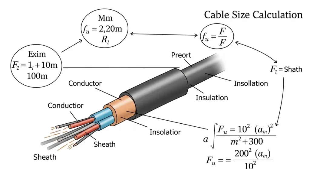
Cable Size Calculation is the process of selecting the correct cross-sectional area (CSA) of an electrical cable so that it can safely carry the required electrical current without overheating, excessive voltage drop, or energy loss. Choosing the right cable size is essential for the safe, reliable, and efficient operation of any electrical installation.
Whether it is a home wiring system, an industrial motor, or a commercial power distribution network, proper cable size calculation helps ensure that the cable performs safely under normal operating conditions and complies with electrical safety standards.
Simple Definition
Cable Size Calculation is the method of determining the appropriate cable size based on the electrical load, current-carrying capacity, voltage drop, cable length, installation conditions, and applicable safety standards.
Simple Explanation
Whenever electric current flows through a cable, the conductor produces heat because of its electrical resistance. If the cable is too small, it may overheat, damage the insulation, waste energy, or even create a fire hazard. On the other hand, using an oversized cable increases installation costs unnecessarily.
To select the correct cable size, electrical engineers consider several important factors, including:
- Load Current – The amount of current the cable must safely carry.
- Voltage Drop – Ensuring the voltage loss along the cable remains within acceptable limits.
- Cable Length – Longer cables require larger sizes to reduce voltage drop.
- Installation Method – Whether the cable is installed in conduit, on cable trays, underground, or in free air.
- Ambient Temperature – Higher surrounding temperatures reduce the cable’s current-carrying capacity.
- Number of Cables Together – Grouped cables generate more heat and may require derating.
- Conductor Material – Copper and aluminum cables have different current-carrying capacities.
- Safety Standards – Cable selection should comply with standards such as IEC, NEC, or local electrical codes.
Practical Example
Suppose you need to install a 5 kW single-phase motor operating at 230 V.
- First, calculate the motor’s load current.
- Determine the cable length and allowable voltage drop.
- Consider the installation method and ambient temperature.
- Select a cable whose current-carrying capacity is higher than the calculated load current while meeting voltage drop and safety requirements.
Using the correct cable size ensures the motor operates efficiently, prevents overheating, minimizes power loss, and extends the lifespan of both the cable and the electrical equipment.
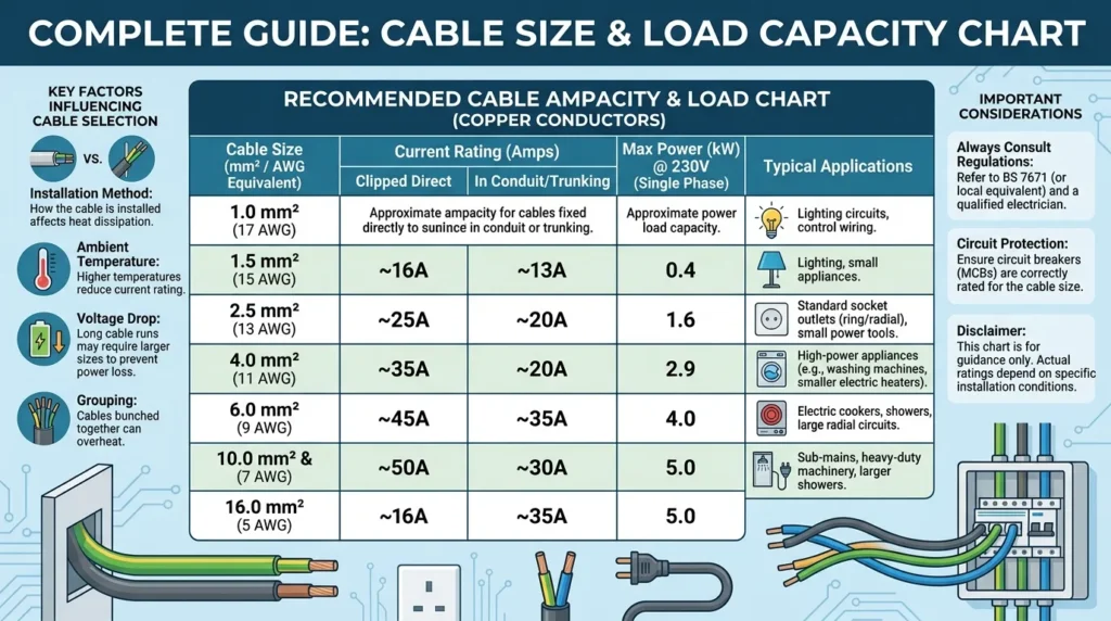
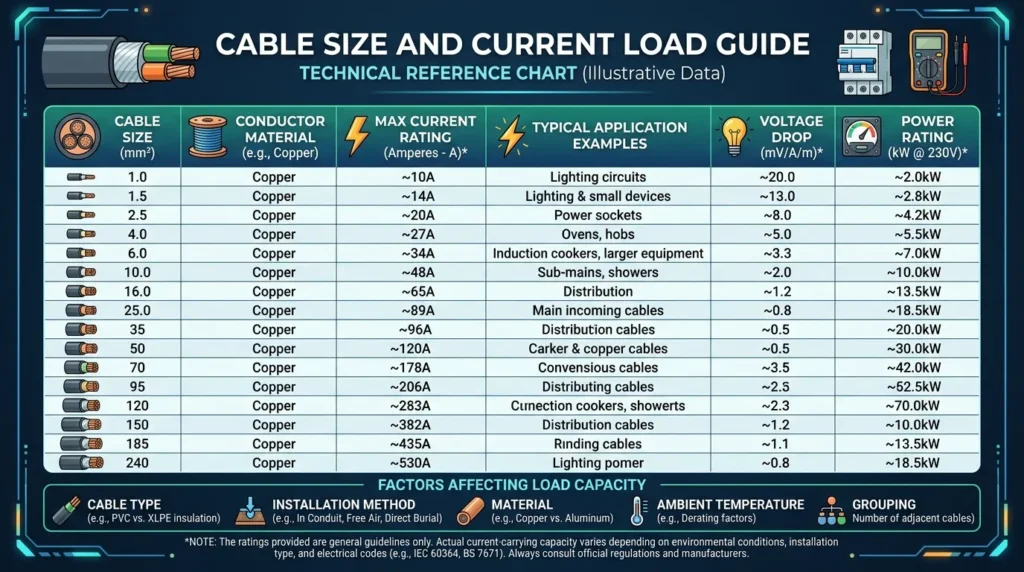
Electrical Cable Size Calculation Chart
The following table provides a general reference for selecting cable sizes based on the approximate current-carrying capacity of copper conductors under typical installation conditions. Actual cable selection should always be verified using the applicable IEC, NEC, BS, or local electrical standards, as factors such as ambient temperature, installation method, cable grouping, and voltage drop can change the required cable size.
| Cable Size (mm²) | Approx. Current Capacity (A) | Typical Applications |
|---|---|---|
| 1.0 mm² | 10–13 A | LED lighting, low-power control circuits |
| 1.5 mm² | 13–18 A | Lighting circuits, ceiling fans |
| 2.5 mm² | 20–24 A | Socket outlets, small appliances |
| 4 mm² | 25–32 A | Water heaters, air conditioners |
| 6 mm² | 32–40 A | Small motors, sub-circuits |
| 10 mm² | 45–63 A | Distribution boards, medium motors |
| 16 mm² | 60–85 A | Industrial feeders, commercial installations |
| 25 mm² | 80–110 A | Heavy machinery, main feeders |
| 35 mm² | 100–140 A | Large distribution panels |
| 50 mm² | 125–170 A | Industrial power distribution |
| 70 mm² | 160–220 A | Large motors, transformer feeders |
| 95 mm² | 200–260 A | High-current industrial applications |
| 120 mm² | 230–310 A | Main distribution systems |
| 150 mm² | 260–350 A | Large commercial and industrial feeders |
| 185 mm² | 300–400 A | High-capacity power distribution |
| 240 mm² | 360–500 A | Substations, utility power systems |
| 300 mm² | 430–580 A | Heavy industrial plants |
| 400 mm² | 520–700 A | Power plants, large substations |
Note: These values are approximate and intended for educational purposes. The actual current-carrying capacity depends on the conductor material, insulation type (PVC or XLPE), installation method (free air, conduit, underground, or cable tray), ambient temperature, cable grouping, and applicable electrical codes.
Electrical Cable Size Calculation Selection Guide
| Factor | Why It Matters | Effect on Cable Size |
|---|---|---|
| Load Current | Determines the current the cable must carry | Higher current requires a larger cable |
| Supply Voltage | Affects current for the same power | Lower voltage usually requires a larger cable |
| Cable Length | Influences voltage drop | Longer cables generally require a larger cable |
| Power Factor | Impacts current in AC systems | Lower power factor increases cable size |
| Installation Method | Affects heat dissipation | Underground and conduit installations may require larger cables |
| Ambient Temperature | Reduces current-carrying capacity | Higher temperatures may require a larger cable |
| Cable Grouping | Multiple cables generate more heat | Apply derating and increase cable size if necessary |
| Conductor Material | Copper and aluminum have different conductivities | Aluminum usually requires a larger cross-sectional area |
| Insulation Type | Determines maximum operating temperature | XLPE generally carries more current than PVC |
| Short-Circuit Rating | Ensures cable survives fault conditions | Higher fault currents may require a larger cable |
Quick Cable Selection Table
| Application | Common Cable Size |
|---|---|
| LED Lighting | 1.5 mm² |
| Socket Outlets | 2.5 mm² |
| Electric Water Heater | 4–6 mm² |
| Split Air Conditioner | 4–6 mm² |
| Small Single-Phase Motor | 6–10 mm² |
| Three-Phase Motor | 10–35 mm² (depends on rating) |
| Main Distribution Board | 16–120 mm² |
| Industrial Feeders | 35–240 mm² |
| Solar PV DC Cables | 4–10 mm² (system dependent) |
| Underground Distribution | 25–400 mm² (project dependent) |
3. Cable Size Calculation Working Principle
The working principle of cable size calculation is based on selecting a cable that can safely carry the required electrical current while maintaining an acceptable voltage drop and complying with electrical safety standards. The correct cable size ensures efficient power transmission, prevents overheating, reduces energy losses, and extends the lifespan of electrical equipment.
The cable must be capable of carrying the expected load under actual installation conditions without exceeding its temperature rating or causing excessive voltage loss.
Step 1: Calculate the Load Current
The first step is to determine how much current the electrical load will draw.
For Single-Phase Systems
[
I = \frac{P}{V \times PF}
]
Where:
- I = Current (A)
- P = Power (W)
- V = Voltage (V)
- PF = Power Factor (For resistive loads, PF ≈ 1)
For Three-Phase Systems
[
I = \frac{P}{\sqrt{3} \times V \times PF}
]
Where:
- I = Current (A)
- P = Power (W)
- V = Line Voltage (V)
- PF = Power Factor
The calculated current becomes the basis for selecting the appropriate cable size.
Step 2: Select the Cable Based on Current-Carrying Capacity
After calculating the load current, choose a cable with a current-carrying capacity (ampacity) greater than the calculated current.
The selected cable should:
- Carry the full load safely
- Avoid excessive heating
- Protect cable insulation from damage
- Provide reliable long-term performance
Electrical standards such as IEC, NEC, or local wiring regulations provide ampacity tables for selecting the correct cable size.
Step 3: Check the Voltage Drop
As electricity travels through a cable, some voltage is lost due to the conductor’s resistance. This is known as voltage drop.
For efficient system performance, the voltage drop should generally remain within:
- 3% for lighting circuits
- 5% for power circuits
If the calculated voltage drop exceeds the recommended limit, a larger cable size should be selected.
Step 4: Consider Installation and Environmental Conditions
Cable performance is affected by its installation environment. These factors must be considered before finalizing the cable size:
- Ambient temperature
- Cable installation method (conduit, cable tray, underground, or free air)
- Grouping of multiple cables
- Type of insulation
- Conductor material (Copper or Aluminum)
- Cable length
- Future load expansion, if applicable
These factors may require applying derating factors, which can increase the required cable size.
Easy Analogy
Imagine electricity flowing through a cable like water flowing through a pipe.
- More water flow requires a larger pipe.
- Longer pipes experience greater pressure loss.
- Similarly, higher electrical current requires a thicker cable, and longer cable runs result in greater voltage drop.
Choosing the correct cable size ensures electricity flows safely and efficiently, just as selecting the right pipe size ensures smooth water flow without excessive pressure loss.
Electrical Cable Design Calculations
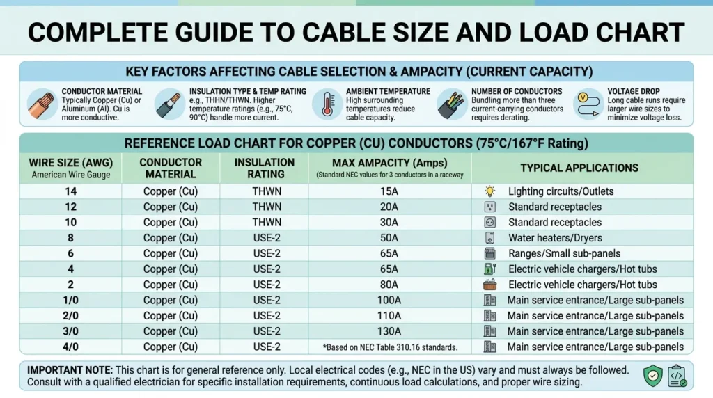
Electrical cable design calculations are the process of determining the most suitable cable size for an electrical installation based on the system’s load requirements and operating conditions. These calculations ensure that the selected cable can safely carry the required current, maintain an acceptable voltage drop, withstand short-circuit faults, and comply with electrical standards such as IEC, NEC, and BS.
During cable design, engineers consider several important factors, including load current, supply voltage, power factor, cable length, conductor material (copper or aluminum), insulation type, installation method, ambient temperature, cable grouping, and short-circuit capacity. By evaluating these parameters, they can select a cable that provides safe, reliable, and energy-efficient operation.
Proper electrical cable design calculations help prevent overheating, excessive voltage drop, insulation damage, and unnecessary energy losses. They also improve equipment performance, extend the service life of cables, reduce maintenance costs, and ensure compliance with electrical safety regulations. For this reason, cable design calculations are an essential part of every residential, commercial, industrial, and renewable energy electrical project.
4. Types of Cable Size Calculation
Cable size calculation can be classified into different types based on the factors considered during cable selection. Each method is used for specific applications to ensure the cable operates safely, efficiently, and in compliance with electrical standards.
The most common methods of cable size calculation are explained below.
4.1 Cable Size Calculation Based on Current-Carrying Capacity (Ampacity)
This is the most commonly used method of cable sizing. It focuses on selecting a cable that can safely carry the required electrical current without overheating or damaging its insulation.
Every cable has a maximum current-carrying capacity (ampacity), which depends on factors such as the conductor material, insulation type, installation method, and ambient temperature. The selected cable should always have an ampacity greater than the expected load current.
How It Works
- Calculate the load current.
- Refer to the standard ampacity tables (IEC, NEC, or local electrical codes).
- Select a cable whose current rating is higher than the calculated current.
- Apply derating factors if the cable is installed in high temperatures or grouped with other cables.
Advantages
- Simple and quick method for cable selection.
- Prevents cable overheating.
- Ensures safe operation under normal load conditions.
- Suitable for most residential and commercial installations.
Common Applications
This method is mainly used for:
- Short cable runs
- Indoor electrical installations
- Residential wiring
- Commercial buildings
- Distribution boards
- Lighting and socket circuits
- Small motors and electrical equipment
Example
Suppose a circuit carries a 40 A load. According to the applicable cable ampacity table, a cable rated for 50 A may be selected to provide a safe operating margin and prevent overheating under normal conditions.
4.2 Cable Size Calculation Based on Voltage Drop
This method of cable size calculation focuses on limiting the voltage drop between the power source and the electrical load. Even if a cable can safely carry the required current, it may still be unsuitable if the voltage drop is too high.
As electrical current travels through a cable, the conductor’s resistance causes a reduction in voltage. This loss is known as voltage drop. Excessive voltage drop can reduce the efficiency of electrical equipment, increase power losses, and cause motors and other devices to operate improperly.
For this reason, electrical standards such as IEC, NEC, and local wiring regulations specify maximum allowable voltage drop limits for different types of installations.
How It Works
The voltage drop is calculated after determining the load current and cable length.
The calculation considers several factors, including:
- Load current
- Cable length
- Conductor material (Copper or Aluminum)
- Cable cross-sectional area
- System voltage
- Power factor (for AC systems)
If the calculated voltage drop exceeds the permissible limit, a larger cable size is selected to reduce resistance and improve voltage regulation.
Why Voltage Drop is Important
Maintaining the correct voltage at the load ensures that electrical equipment performs efficiently and safely.
Excessive voltage drop may result in:
- Poor motor starting performance
- Reduced motor torque
- Dim or flickering lights
- Lower efficiency of electrical equipment
- Increased heat generation in cables
- Higher energy losses
- Reduced equipment lifespan
Keeping the voltage drop within acceptable limits helps maintain stable system performance and improves energy efficiency.
Typical Allowable Voltage Drop
Most electrical standards recommend the following limits:
- Lighting circuits: Up to 3%
- Power circuits: Up to 5%
- Critical industrial equipment: As specified by the applicable design standard or manufacturer
If these limits are exceeded, the cable size should be increased.
Advantages
- Maintains proper voltage at the load.
- Improves the efficiency of electrical systems.
- Reduces power and energy losses.
- Prevents equipment malfunction caused by low voltage.
- Increases the lifespan of motors, pumps, and other electrical devices.
- Ensures compliance with electrical installation standards.
Common Applications
Voltage drop-based cable sizing is commonly used for:
- Long-distance electrical wiring
- Rural electrification projects
- Underground cable installations
- Industrial power distribution systems
- Large commercial buildings
- Agricultural irrigation systems
- Street lighting installations
- Solar photovoltaic (PV) systems
- Water pumping stations
Practical Example
Suppose a 15 kW motor is installed 180 meters away from the main distribution panel. Although a 10 mm² copper cable may safely carry the required current, the long cable length may cause the voltage drop to exceed the recommended limit.
After performing the voltage drop calculation, the engineer may choose a 16 mm² or 25 mm² cable instead. The larger conductor has lower resistance, reducing voltage loss and ensuring the motor receives sufficient voltage for reliable and efficient operation.
4.3 Cable Size Calculation Based on Short-Circuit Capacity
This method of cable size calculation ensures that the cable can withstand the high current produced during a short circuit (fault) for a specified period without suffering permanent damage.
Under normal operating conditions, a cable carries only the load current. However, if a fault such as a short circuit or ground fault occurs, an extremely high current may flow through the cable for a few milliseconds or seconds until the protective device (fuse or circuit breaker) disconnects the fault.
During this short period, the cable experiences intense heating. If the cable is not designed to withstand this thermal stress, its insulation may melt, the conductor may deform, or the cable may fail completely.
Therefore, besides current-carrying capacity and voltage drop, engineers also verify that the selected cable has adequate short-circuit withstand capacity.
How It Works
The short-circuit capacity of a cable depends on several factors, including:
- Magnitude of the fault current
- Duration of the fault
- Conductor material (Copper or Aluminum)
- Cross-sectional area of the conductor
- Type of cable insulation
- Maximum permissible conductor temperature
The cable must safely withstand the fault current until the protective device clears the fault.
If the calculated fault current exceeds the cable’s short-circuit rating, a larger cable size or a faster protective device must be selected.
Why Short-Circuit Capacity is Important
During a short circuit, the current may become 10 to 50 times higher than the normal operating current.
If the cable cannot tolerate this fault current, it may result in:
- Melting of cable insulation
- Damage to the conductor
- Fire hazards
- Failure of electrical equipment
- Extended power outages
- Increased repair and replacement costs
Selecting a cable with adequate short-circuit withstand capacity improves the overall safety and reliability of the electrical system.
Factors Affecting Short-Circuit Capacity
Several factors influence a cable’s ability to withstand fault current:
- Conductor cross-sectional area (larger cables withstand higher fault currents)
- Conductor material (Copper generally withstands higher fault currents than Aluminum for the same size)
- Fault clearing time of circuit breakers or fuses
- Insulation type (PVC, XLPE, EPR, etc.)
- Initial and maximum conductor temperatures
- Expected fault current at the installation point
Electrical engineers use these factors along with IEC, NEC, or local standards to verify cable suitability.
Advantages
- Protects cables during fault conditions.
- Prevents insulation damage and conductor failure.
- Improves electrical system safety.
- Reduces the risk of fire caused by short circuits.
- Increases the reliability of industrial power systems.
- Ensures compliance with international electrical standards.
Common Applications
Cable sizing based on short-circuit capacity is widely used in:
- Industrial power systems
- High-power electrical installations
- Electrical substations
- Power generation plants
- Large manufacturing facilities
- Motor Control Centers (MCCs)
- Power Control Centers (PCCs)
- High-voltage and medium-voltage distribution systems
- Commercial buildings with high fault levels
Practical Example
Suppose a 400 A industrial feeder is supplied from a transformer capable of producing a 25 kA short-circuit current. Although a particular cable may safely carry the 400 A load under normal conditions, it must also withstand the 25 kA fault current until the circuit breaker trips.
If the cable’s short-circuit withstand rating is lower than the expected fault current, engineers must either select a larger cable with a higher thermal withstand capacity or use a faster protective device to reduce the fault duration.
By considering short-circuit capacity during cable size calculation, engineers ensure that the cable remains safe and functional even under severe fault conditions, protecting both the electrical installation and connected equipment.
4.4 Cable Size Calculation Based on Installation Method
The installation method is an important factor in cable size calculation because it directly affects how efficiently a cable can dissipate heat. When electrical current flows through a cable, the conductor generates heat due to its electrical resistance. The surrounding environment determines how quickly this heat can escape.
If heat is not dissipated effectively, the cable temperature rises, reducing its current-carrying capacity (ampacity). Therefore, the same cable may carry different amounts of current depending on how and where it is installed.
For this reason, electrical standards such as IEC, NEC, and local wiring regulations provide different current ratings for cables installed under different conditions.
How It Works
When selecting a cable, engineers first calculate the required load current and then consider the installation method.
Different installation methods provide different cooling conditions:
- Cables with better airflow can dissipate heat more effectively.
- Cables enclosed in conduits or buried underground retain more heat.
- Poor heat dissipation reduces the cable’s allowable current.
- A larger cable may be required to compensate for reduced cooling.
This process ensures that the cable operates safely without exceeding its maximum permissible temperature.
Common Installation Methods
1. Cable Installed in Free Air
Cables installed in open air have excellent ventilation and can release heat efficiently.
Features
- Best cooling conditions
- Higher current-carrying capacity
- Lower operating temperature
- Often requires a smaller cable size compared to enclosed installations
Typical Applications
- Outdoor overhead wiring
- Cable racks
- Industrial open installations
2. Underground (Direct Buried) Installation
Underground cables are surrounded by soil, which restricts heat dissipation compared to free air.
The cable size depends on:
- Soil temperature
- Soil thermal resistivity
- Burial depth
- Moisture content of the soil
Poor soil conditions may require selecting a larger cable.
Typical Applications
- Underground power distribution
- Utility supply networks
- Industrial plants
- Residential underground services
3. Cable Installed in Conduit
When cables are installed inside PVC or metal conduits, airflow around the cable is limited.
This causes:
- Reduced heat dissipation
- Higher cable operating temperature
- Lower current-carrying capacity
If multiple cables share the same conduit, additional derating factors must also be applied.
Typical Applications
- Residential wiring
- Commercial buildings
- Industrial electrical installations
4. Cable Installed on Cable Tray
Cable trays provide better ventilation than conduits but may still require derating if many cables are grouped together.
Factors affecting cable size include:
- Number of cables on the tray
- Spacing between cables
- Tray type (perforated or solid)
- Ambient temperature
Proper spacing improves cooling and increases cable efficiency.
Typical Applications
- Factories
- Data centers
- Commercial buildings
- Power plants
- Industrial control rooms
Why Installation Method Matters
Ignoring the installation method can lead to incorrect cable selection, resulting in:
- Cable overheating
- Insulation deterioration
- Reduced cable lifespan
- Increased power losses
- Frequent tripping of protective devices
- Potential fire hazards
Selecting the cable according to its installation method ensures safe operation, reliable performance, and compliance with electrical standards.
Advantages
- Ensures accurate cable sizing for actual installation conditions.
- Prevents overheating caused by poor heat dissipation.
- Improves the lifespan of cables and insulation.
- Increases the safety and reliability of electrical installations.
- Helps comply with IEC, NEC, and local electrical standards.
Common Applications
Cable sizing based on the installation method is commonly used in:
- Residential wiring systems
- Commercial buildings
- Industrial plants
- Underground distribution networks
- Cable tray installations
- Substations
- Power plants
- Renewable energy projects such as solar and wind farms
Practical Example
Suppose a 70 A load needs to be supplied to an industrial machine.
- If the cable is installed in free air, a 16 mm² copper cable may safely carry the load.
- If the same cable is installed inside a conduit or buried underground, its heat dissipation is reduced, and a 25 mm² cable may be required to maintain safe operating temperatures.
This example shows why the installation method is always considered during cable size calculation. Selecting the correct cable based on installation conditions ensures efficient heat dissipation, safe operation, and long-term system reliability.
5. Main Components of Cable Size Calculation
Accurate cable size calculation depends on several important electrical and environmental factors. These components determine the amount of current a cable must carry, the allowable voltage drop, and the cable’s ability to operate safely under different installation conditions.
Ignoring any of these factors can lead to an undersized cable, causing overheating, excessive power loss, equipment malfunction, or even fire hazards. Therefore, every electrical engineer or technician should evaluate all the following components before selecting a cable.
5.1 Load Power
Load power is the total electrical power consumed by the equipment connected to the cable. It is the starting point for calculating the load current and selecting the appropriate cable size.
Load power is usually expressed in:
- Watts (W)
- Kilowatts (kW)
- Megawatts (MW)
The higher the load power, the greater the current drawn by the equipment, which generally requires a larger cable.
Factors to Consider
- Total connected load
- Continuous or intermittent operation
- Future load expansion
- Type of electrical equipment
Examples
- Residential lighting circuits
- Air conditioners
- Electric heaters
- Industrial motors
- Pumps and compressors
5.2 Supply Voltage
The supply voltage determines the amount of current required for a given power output.
For the same power rating:
- Higher voltage results in lower current
- Lower voltage results in higher current
Since cable size is primarily selected based on current, supply voltage plays a vital role in cable sizing.
Common supply systems include:
- Single-phase systems (120 V, 230 V, etc.)
- Three-phase systems (400 V, 415 V, 480 V, etc.)
Three-phase systems generally require smaller conductor sizes for the same power because the current is lower.
Typical Applications
- Residential buildings (single-phase)
- Commercial buildings
- Industrial power systems (three-phase)
5.3 Power Factor (PF)
Power factor represents how efficiently electrical power is converted into useful work.
It is especially important in AC systems, where motors, transformers, and inductive loads draw both real and reactive power.
A lower power factor means:
- Higher current
- Larger cable size
- Increased power losses
- Greater voltage drop
Typical power factor values:
- Resistive loads: 1.0
- Industrial motors: 0.8–0.9
- Commercial installations: 0.85–0.95
Improving the power factor reduces the required current and can help reduce cable size.
5.4 Cable Length
Cable length has a significant effect on voltage drop.
As the cable becomes longer:
- Electrical resistance increases.
- Voltage drop becomes larger.
- More energy is lost as heat.
- A larger cable may be required.
For short cable runs, voltage drop is usually minimal.
For long-distance installations, engineers often increase the conductor size to keep voltage drop within acceptable limits.
Common Applications
- Underground distribution
- Rural electrification
- Solar PV systems
- Street lighting
- Water pumping stations
5.5 Conductor Material
The conductor material determines the cable’s electrical conductivity, resistance, mechanical strength, and cost.
The two most commonly used conductor materials are:
Copper
Copper is the preferred conductor for most electrical installations because it offers:
- Excellent electrical conductivity
- Higher current-carrying capacity
- Lower electrical resistance
- Better mechanical strength
- Longer service life
Common Applications
- Residential wiring
- Commercial buildings
- Industrial installations
- Control panels
Aluminum
Aluminum is lighter and more economical than copper but has lower electrical conductivity.
Compared with copper, aluminum cables generally require a larger cross-sectional area to carry the same current.
Advantages
- Lower cost
- Lightweight
- Suitable for long-distance transmission
Common Applications
- Utility distribution systems
- Overhead transmission lines
- Large industrial feeders
5.6 Insulation Type
Cable insulation protects the conductor from moisture, heat, chemicals, and mechanical damage.
The insulation type also determines the cable’s maximum operating temperature, which directly affects its current-carrying capacity.
The two most common insulation materials are:
PVC (Polyvinyl Chloride)
PVC-insulated cables are widely used because they are:
- Economical
- Flexible
- Easy to install
- Resistant to moisture and chemicals
Typical Maximum Operating Temperature: 70°C
Applications
- Residential wiring
- Commercial buildings
- General electrical installations
XLPE (Cross-Linked Polyethylene)
XLPE insulation provides better electrical and thermal performance than PVC.
Its advantages include:
- Higher temperature rating
- Higher current-carrying capacity
- Better insulation properties
- Improved moisture resistance
- Longer service life
Typical Maximum Operating Temperature: 90°C
Applications
- Industrial plants
- Underground cables
- High-voltage systems
- Power distribution networks
Why These Components Are Important
All of these factors work together to determine the correct cable size.
Before selecting a cable, engineers evaluate:
- Load power
- Supply voltage
- Power factor
- Cable length
- Conductor material
- Insulation type
- Installation method
- Ambient temperature
- Allowable voltage drop
- Applicable electrical standards
Considering each of these components ensures the cable operates safely, minimizes energy losses, prevents overheating, and provides reliable long-term performance in any electrical installation.
6. Advantages of Cable Size Calculation
Proper cable size calculation is one of the most important steps in designing a safe and efficient electrical system. Selecting the correct cable size ensures that electrical equipment receives the required voltage while preventing overheating, energy losses, and premature equipment failure.
Whether the installation is residential, commercial, or industrial, accurate cable sizing improves system reliability and reduces operating costs over the long term.
Key Advantages of Cable Size Calculation
1. Prevents Cable Overheating
A correctly sized cable can safely carry the required current without exceeding its maximum operating temperature. This prevents overheating, insulation damage, and conductor deterioration.
2. Reduces Fire Risk
Overloaded or undersized cables generate excessive heat, which can damage insulation and increase the risk of electrical fires. Proper cable sizing significantly improves electrical safety.
3. Improves System Efficiency
Using the correct cable minimizes electrical resistance and power losses, allowing electricity to reach connected equipment more efficiently.
4. Minimizes Voltage Drop
Proper cable sizing keeps voltage drop within the limits recommended by electrical standards, ensuring equipment operates at its rated voltage and performance.
5. Extends Equipment Life
Stable voltage and reduced overheating protect motors, transformers, pumps, and other electrical equipment, helping them operate reliably for many years.
6. Ensures Compliance with Electrical Standards
Correct cable selection helps meet the requirements of standards such as IEC, NEC, and local electrical codes, reducing the risk of inspection failures and safety issues.
7. Improves System Reliability
Correctly sized cables reduce unexpected breakdowns, nuisance tripping, and electrical faults, ensuring continuous and dependable operation.
8. Reduces Energy Losses
Larger-than-required resistance causes unnecessary power loss in the form of heat. Proper cable sizing reduces these losses and improves overall energy efficiency.
9. Supports Future Expansion
By considering future load growth during cable selection, engineers can avoid costly cable replacements when additional equipment is installed.
10. Lowers Long-Term Operating Costs
Although the initial investment may be slightly higher, selecting the correct cable size reduces maintenance expenses, repair costs, energy losses, and equipment replacement over the cable’s service life.
Real-World Benefits
Proper cable size calculation provides several practical benefits in everyday electrical installations, including:
- Stable motor starting and operation
- Reliable performance of industrial machinery
- Reduced voltage fluctuations
- Lower maintenance and repair costs
- Improved energy efficiency
- Safe residential wiring
- Reliable commercial electrical systems
- Enhanced industrial power distribution
- Longer service life for cables and equipment
Correct cable sizing is a long-term investment that improves safety, reliability, and cost efficiency throughout the life of an electrical installation.
7. Disadvantages and Limitations of Cable Size Calculation
Although cable size calculation is essential for every electrical installation, it also has certain challenges and limitations. Engineers must carefully consider all influencing factors to avoid incorrect cable selection.
If calculations are inaccurate or important factors are ignored, the electrical system may experience poor performance, increased costs, or safety hazards.
Common Limitations
1. Requires Technical Knowledge
Accurate cable sizing requires a good understanding of electrical principles, including current calculation, voltage drop, power factor, derating factors, and electrical standards. Beginners may find the process challenging without proper training.
2. Calculation Errors Can Cause Serious Problems
Incorrect calculations may result in selecting an undersized or oversized cable.
An undersized cable can cause:
- Overheating
- Insulation failure
- Excessive voltage drop
- Equipment damage
- Fire hazards
An oversized cable may lead to unnecessary project costs.
3. Environmental Conditions Affect Performance
Cable performance changes with environmental conditions such as:
- High ambient temperature
- Underground installation
- Cable grouping
- Poor ventilation
- Soil thermal resistivity
These conditions require derating factors, making cable selection more complex.
4. Oversized Cables Increase Project Cost
Choosing a cable much larger than necessary increases:
- Material costs
- Transportation costs
- Installation expenses
- Cable tray and conduit sizes
- Overall project budget
Proper optimization is therefore important.
5. Future Load Estimation Can Be Difficult
Engineers often allow for future expansion, but accurately predicting future electrical demand is not always easy. Incorrect estimates may lead to either insufficient capacity or unnecessary oversizing.
6. Requires Compliance with Electrical Standards
Cable selection must comply with applicable standards such as IEC, NEC, or local wiring regulations. Keeping up with updated standards and applying them correctly requires experience and continuous learning.
7. Site Conditions May Change
Actual installation conditions sometimes differ from the original design. Changes in cable routing, installation method, ambient temperature, or equipment location may require the cable size to be recalculated.
Practical Challenges
Some common challenges faced during cable size calculation include:
- Determining the actual connected load
- Measuring accurate cable length
- Selecting appropriate derating factors
- Maintaining allowable voltage drop
- Calculating prospective short-circuit current
- Choosing between copper and aluminum conductors
- Balancing safety, performance, and project cost
Despite these limitations, cable size calculation remains an essential part of electrical system design. By carefully considering load current, voltage drop, installation conditions, environmental factors, and applicable standards, engineers can select the most suitable cable for safe, efficient, and reliable operation. Proper planning and accurate calculations help prevent costly mistakes while ensuring long-term electrical safety and performance.
8. Applications of Cable Size Calculation
Cable size calculation is an essential part of every electrical installation, regardless of its size or complexity. From small residential wiring projects to large industrial power systems, selecting the correct cable size ensures safe operation, efficient power transmission, and compliance with electrical standards.
Proper cable sizing helps prevent overheating, minimizes voltage drop, reduces energy losses, and protects electrical equipment from damage. As a result, cable size calculation is used in almost every field of electrical engineering.
Below are some of the most common applications.
8.1 Residential Wiring
In residential buildings, cable size calculation ensures that household wiring can safely carry the required electrical load without overheating or causing voltage fluctuations.
Proper cable selection improves the safety and reliability of home electrical systems while protecting appliances from low-voltage conditions.
Common Applications
- Lighting circuits
- Socket outlets
- Air conditioners
- Ceiling fans
- Electric water heaters
- Kitchen appliances
- Home distribution boards
- Electric vehicle (EV) chargers
Benefits
- Safe household wiring
- Reduced fire hazards
- Stable voltage supply
- Longer appliance lifespan
8.2 Industrial Installations
Industrial facilities require accurate cable size calculation because they operate high-power equipment that draws large amounts of current.
Proper cable sizing ensures reliable operation of machinery while minimizing power losses and equipment downtime.
Common Applications
- Industrial motors
- Motor Control Centers (MCCs)
- Power Control Centers (PCCs)
- Control panels
- Heavy machinery
- Production lines
- Pumps and compressors
- Conveyor systems
- Industrial generators
Benefits
- Reliable motor performance
- Reduced maintenance costs
- Improved production efficiency
- Enhanced electrical safety
8.3 Commercial Buildings
Commercial buildings contain a wide variety of electrical loads that require carefully designed cable systems.
Proper cable sizing helps maintain voltage stability and ensures continuous operation of essential building services.
Common Applications
- HVAC systems
- Elevators and escalators
- Data centers
- Office lighting
- Distribution panels
- Fire alarm systems
- Security and CCTV systems
- Shopping malls
- Hospitals and hotels
Benefits
- Reliable building operations
- Reduced energy losses
- Stable voltage for sensitive equipment
- Improved occupant safety
8.4 Renewable Energy Systems
Renewable energy installations require precise cable sizing to maximize energy transfer efficiency and minimize voltage losses.
Since many renewable energy systems involve long cable runs between power sources and inverters or batteries, proper cable selection is especially important.
Common Applications
- Solar photovoltaic (PV) systems
- Solar panel string wiring
- Battery banks
- Hybrid solar systems
- Wind power systems
- Inverter connections
- Charge controllers
- Off-grid power systems
Benefits
- Improved energy efficiency
- Lower voltage drop
- Higher system performance
- Increased equipment lifespan
8.5 Underground Power Distribution
Underground cable systems are widely used for utility power distribution, urban infrastructure, and industrial facilities.
Because underground cables dissipate heat differently than cables installed in free air, accurate cable size calculation is essential to ensure safe operation.
Common Applications
- Utility power supply
- Underground distribution networks
- Residential housing societies
- Commercial complexes
- Industrial parks
- Airports
- Railway power systems
- Smart city infrastructure
Benefits
- Reliable power distribution
- Reduced power losses
- Improved public safety
- Long service life of underground cables
8.6 Electrical Substations
Electrical substations use large-capacity cables to transmit and distribute electrical power between transformers, switchgear, and outgoing feeders.
Proper cable sizing is critical because substations handle high currents and fault levels.
Common Applications
- Transformer connections
- Switchgear panels
- Busbar feeders
- Protection and control circuits
- Incoming and outgoing feeders
Benefits
- Safe high-current operation
- Improved system reliability
- Better fault protection
8.7 Power Generation Plants
Power plants require accurately sized cables to carry large amounts of electrical power from generators to transformers and distribution equipment.
Common Applications
- Thermal power plants
- Hydroelectric power plants
- Solar power plants
- Wind farms
- Diesel generator systems
- Gas power plants
Benefits
- Efficient power transmission
- Reduced energy losses
- Reliable operation of generation equipment
8.8 Infrastructure and Transportation
Modern transportation systems rely heavily on properly sized electrical cables for safe and continuous operation.
Common Applications
- Airports
- Railway stations
- Metro systems
- Tunnels
- Bridges
- Street lighting
- Traffic signal systems
Benefits
- Reliable public infrastructure
- Improved electrical safety
- Reduced maintenance requirements
Why Cable Size Calculation Is Important in Every Project
Regardless of the type of electrical installation, selecting the correct cable size is essential because it:
- Prevents cable overheating
- Reduces voltage drop
- Improves energy efficiency
- Protects electrical equipment
- Extends cable service life
- Minimizes maintenance costs
- Ensures compliance with IEC, NEC, and local electrical standards
- Enhances overall system safety and reliability
From residential homes to large industrial plants and renewable energy systems, every electrical project requires proper cable size calculation to ensure safe, efficient, and long-lasting electrical performance.
9. Comparison Section
Difference Between Copper and Aluminum Cable Selection
Many students ask about the difference between copper and aluminum cable in cable sizing.
| Feature | Copper Cable | Aluminum Cable |
|---|---|---|
| Conductivity | High | Lower |
| Size Required | Smaller | Larger |
| Cost | Higher | Lower |
| Weight | Heavy | Light |
| Durability | Better | Moderate |
This difference between copper and aluminum cable affects Cable Size Calculation significantly.
10. Cable Size Selection Guide
Selecting the correct cable size is a critical step in designing a safe, efficient, and reliable electrical system. An undersized cable can overheat, cause excessive voltage drop, and create fire hazards, while an oversized cable unnecessarily increases project costs.
By following a systematic cable selection process, electrical engineers and technicians can ensure that the cable meets the electrical load requirements, complies with safety standards, and provides reliable long-term performance.
Step 1: Calculate the Load Current
The first step is to determine the amount of current the cable must safely carry.
Calculate the load current using the appropriate formula based on the type of electrical system.
- Single-phase system: Use the single-phase current formula.
- Three-phase system: Use the three-phase current formula.
Accurate current calculation is the foundation of proper cable size selection.
Tip: Always use the maximum expected operating load rather than the average load.
Step 2: Choose the Conductor Material
Select the conductor material based on the project’s technical and economic requirements.
Copper Conductors
Choose copper when:
- High electrical efficiency is required.
- Space is limited.
- Better conductivity is needed.
- High mechanical strength is important.
- Long service life is desired.
Aluminum Conductors
Choose aluminum when:
- Reducing project cost is a priority.
- Lightweight cables are preferred.
- Long-distance power distribution is involved.
- Larger cable sizes can be accommodated.
The conductor material directly affects current-carrying capacity, voltage drop, and installation cost.
Step 3: Verify the Current-Carrying Capacity
After selecting the conductor material, compare the calculated load current with the cable’s ampacity.
The selected cable must:
- Carry the full load safely.
- Operate below its maximum temperature rating.
- Comply with IEC, NEC, or local electrical standards.
If the cable cannot safely carry the calculated current, choose the next larger size.
Step 4: Check the Voltage Drop
Voltage drop increases with cable length and load current.
Calculate the voltage drop and ensure it remains within the recommended limits.
Typical limits are:
- Up to 3% for lighting circuits.
- Up to 5% for power circuits.
If the voltage drop exceeds the allowable limit, increase the cable size.
Step 5: Consider the Installation Method
The installation method affects how efficiently the cable can dissipate heat.
Different installation methods require different cable sizes.
Examples include:
- Free air installation
- Underground installation
- Conduit installation
- Cable tray installation
- Buried duct systems
Underground or enclosed installations usually require larger cables because heat dissipation is lower.
Step 6: Consider Environmental Conditions
Environmental factors significantly influence cable performance.
Always evaluate:
- Ambient temperature
- Cable grouping
- Ventilation
- Soil thermal resistivity (for underground cables)
- Moisture and humidity
- Exposure to sunlight
- Chemical or corrosive environments
Apply the appropriate derating factors whenever required.
Step 7: Check Short-Circuit Capacity
Ensure that the selected cable can safely withstand the maximum fault current until the protective device disconnects the circuit.
The cable should have adequate thermal withstand capacity to avoid insulation damage during short-circuit conditions.
This step is especially important in:
- Industrial plants
- Electrical substations
- High-power distribution systems
Step 8: Add a Safety Margin
It is good engineering practice to allow for future expansion.
Many engineers provide approximately 20% additional capacity so the cable can accommodate future load increases without requiring replacement.
This reduces future installation costs and improves system flexibility.
Step 9: Follow Electrical Standards
Always select cables according to recognized electrical standards, such as:
- IEC (International Electrotechnical Commission)
- NEC (National Electrical Code)
- BS Standards
- Local electrical regulations and utility requirements
Following these standards ensures safe, legal, and reliable electrical installations.
Quick Selection Checklist
Before finalizing a cable size, confirm the following:
- ✅ Load current has been calculated accurately.
- ✅ Correct conductor material (Copper or Aluminum) has been selected.
- ✅ Cable ampacity is sufficient.
- ✅ Voltage drop is within allowable limits.
- ✅ Installation method has been considered.
- ✅ Environmental derating factors have been applied.
- ✅ Short-circuit withstand capacity has been verified.
- ✅ Safety margin for future expansion has been included.
- ✅ Cable complies with applicable electrical standards.
Best Practice for Beginners
Never guess the cable size. Always perform proper cable size calculations based on load current, voltage drop, installation conditions, conductor material, and applicable electrical standards.
Choosing the correct cable not only protects electrical equipment but also improves system efficiency, enhances safety, reduces maintenance costs, and ensures reliable operation throughout the life of the electrical installation.
11. Common Cable Size Calculation Problems and Solutions
Even when a cable is installed correctly, problems can occur if the cable size is not selected properly or if the electrical load changes over time. Incorrect cable sizing can lead to overheating, excessive voltage drop, frequent breaker trips, equipment damage, and reduced system efficiency.
Regular inspections, preventive maintenance, and routine electrical testing help identify these problems early and improve the safety and reliability of the electrical system.
Below are some of the most common cable-related problems, their causes, and practical solutions.
Problem 1: Cable Overheating
Symptoms
- Cable feels unusually hot.
- Insulation becomes soft or discolored.
- Burning smell near the cable.
- Cable temperature increases during normal operation.
Possible Causes
- Undersized cable
- Overloaded circuit
- Poor ventilation
- High ambient temperature
- Loose electrical connections
Solution
- Recalculate the load current.
- Select a cable with a higher current-carrying capacity.
- Reduce the connected load if necessary.
- Improve cable ventilation.
- Tighten or replace loose connections.
Problem 2: Low Voltage at the Load End
Symptoms
- Lights become dim.
- Motors start slowly.
- Equipment operates inefficiently.
- Electronic devices malfunction.
Possible Causes
- Excessive voltage drop
- Long cable runs
- Cable size too small
- High load current
Solution
- Calculate the voltage drop.
- Increase the cable size.
- Reduce the cable length where possible.
- Improve the power factor for large inductive loads.
Problem 3: Circuit Breaker Trips Frequently
Symptoms
- Breaker trips repeatedly.
- Electrical equipment shuts down unexpectedly.
- Frequent interruptions in power supply.
Possible Causes
- Excessive load current
- Short circuit
- Ground fault
- Incorrect cable size
- Faulty electrical equipment
Solution
- Measure the actual load current.
- Check the cable’s current rating.
- Inspect the circuit for short circuits or ground faults.
- Replace undersized cables if necessary.
- Repair or replace faulty equipment.
Problem 4: Cable Insulation Damage
Symptoms
- Cracked or melted insulation
- Visible burn marks
- Exposed conductors
- Electrical leakage
Possible Causes
- Continuous overheating
- Overloading
- Mechanical damage
- Chemical exposure
- Aging of insulation
Solution
- Replace the damaged cable immediately.
- Install a cable with a higher temperature rating if required.
- Reduce excessive loading.
- Protect cables from mechanical damage and harsh environmental conditions.
- Perform regular insulation resistance testing.
Problem 5: Unequal Current in Three-Phase Systems
Symptoms
- Different current values in each phase
- Motor overheating
- Neutral conductor overheating
- Reduced system efficiency
Possible Causes
- Unbalanced electrical loads
- Uneven phase distribution
- Faulty equipment
- Loose phase connections
Solution
- Balance the electrical load across all three phases.
- Redistribute single-phase loads evenly.
- Inspect all phase connections.
- Replace faulty equipment if required.
Problem 6: Excessive Power Loss
Symptoms
- High electricity bills
- Hot cables during operation
- Reduced system efficiency
Possible Causes
- Small cable size
- High cable resistance
- Long cable runs
- Poor conductor material selection
Solution
- Upgrade to a larger cable size.
- Use copper conductors where appropriate.
- Minimize unnecessary cable length.
- Improve overall system design.
Problem 7: Premature Equipment Failure
Symptoms
- Frequent motor failures
- Reduced equipment lifespan
- Unstable equipment performance
Possible Causes
- Low operating voltage
- Incorrect cable selection
- Continuous voltage fluctuations
- Excessive heating
Solution
- Verify cable sizing calculations.
- Ensure voltage drop remains within allowable limits.
- Replace undersized cables.
- Monitor electrical parameters regularly.
Preventive Maintenance Tips
Routine maintenance helps prevent cable-related failures and extends the life of the entire electrical system.
Recommended Practices
- Inspect cables for physical damage and overheating.
- Check the tightness of electrical connections.
- Measure load current periodically.
- Test insulation resistance.
- Monitor voltage drop under full load.
- Verify breaker and fuse ratings.
- Balance three-phase loads regularly.
- Replace damaged or aging cables promptly.
- Follow IEC, NEC, or local electrical standards during maintenance.
Key Takeaway
Most cable-related problems are caused by incorrect cable sizing, excessive loading, poor installation practices, or inadequate maintenance. Performing accurate cable size calculations and carrying out routine inspections can prevent overheating, voltage drop, equipment failure, and unnecessary downtime.
Regular testing and preventive maintenance are essential for ensuring safe, efficient, and reliable operation of residential, commercial, and industrial electrical systems.
12. Future Trends in Cable Size Calculation
The field of cable size calculation is continuously evolving as electrical systems become more advanced, energy-efficient, and digitally connected. Modern buildings, industrial facilities, renewable energy projects, and smart grids require cables that can safely handle higher loads while providing better performance and reliability.
At the same time, new technologies are making cable selection more accurate through intelligent monitoring systems, advanced conductor materials, and specialized software. These innovations help engineers improve safety, reduce energy losses, and extend the lifespan of electrical installations.
Below are some of the most important future trends shaping cable size calculation.
12.1 Smart Cable Monitoring
One of the biggest advancements in electrical systems is the use of smart cable monitoring technology.
Modern cables can be equipped with sensors that continuously monitor their operating condition in real time.
These systems can detect:
- Cable temperature
- Load current
- Overloading
- Voltage drop
- Insulation deterioration
- Potential fault conditions
Real-time monitoring allows maintenance teams to identify problems before they lead to equipment failure or power outages.
Benefits
- Early fault detection
- Reduced maintenance costs
- Improved system reliability
- Increased electrical safety
- Longer cable service life
12.2 Fire-Resistant and Low-Smoke Cables
As safety regulations become stricter, fire-resistant cables are increasingly being used in critical facilities.
These cables continue operating for a specified period during a fire, allowing emergency systems to function while occupants evacuate safely.
Many modern installations also use Low Smoke Zero Halogen (LSZH) cables, which produce very little smoke and no toxic halogen gases when exposed to fire.
Common Applications
- Hospitals
- High-rise buildings
- Airports
- Railway stations
- Data centers
- Shopping malls
- Emergency lighting systems
- Fire alarm systems
Benefits
- Improved fire safety
- Reduced smoke generation
- Better protection for people and equipment
- Compliance with modern safety standards
12.3 High-Efficiency Conductor Materials
Researchers continue developing new conductor materials that offer better electrical performance than conventional conductors.
Future cables may use:
- Improved copper alloys
- Advanced aluminum alloys
- Composite conductor technologies
These materials can provide:
- Lower electrical resistance
- Higher current-carrying capacity
- Reduced energy losses
- Lower cable weight
- Improved mechanical strength
Such developments will enable more efficient power transmission while reducing installation costs.
12.4 Sustainable and Eco-Friendly Cable Manufacturing
Environmental sustainability is becoming a major focus in the electrical industry.
Manufacturers are developing cables using environmentally friendly materials and production processes.
Future cables may include:
- Recyclable insulation materials
- Halogen-free compounds
- Low-carbon manufacturing methods
- Environmentally safe flame-retardant materials
These innovations help reduce environmental impact while maintaining high electrical performance and safety.
12.5 Advanced Cable Size Calculation Software
Manual cable calculations are increasingly being replaced by intelligent engineering software.
Modern design tools can automatically consider:
- Load current
- Voltage drop
- Short-circuit capacity
- Ambient temperature
- Installation method
- Cable grouping
- Derating factors
- International electrical standards
This reduces calculation errors and speeds up electrical system design.
Benefits
- Faster engineering design
- Greater accuracy
- Automatic compliance with standards
- Reduced human error
12.6 Smart Grids and Renewable Energy Integration
The expansion of smart grids and renewable energy systems is changing how cables are selected.
Modern electrical networks must accommodate:
- Solar photovoltaic (PV) systems
- Wind farms
- Battery energy storage systems
- Electric vehicle (EV) charging stations
- Distributed power generation
These applications require more precise cable sizing to handle variable loads and bidirectional power flow efficiently.
12.7 Artificial Intelligence (AI) in Cable Design
Artificial Intelligence is beginning to assist engineers in optimizing cable selection.
AI-based engineering tools can analyze:
- Electrical load patterns
- Historical operating data
- Environmental conditions
- Future demand forecasts
Based on this analysis, AI can recommend the most suitable cable size, helping reduce energy losses and installation costs while improving overall system reliability.
Future Outlook
The future of cable size calculation is moving toward smarter, safer, and more energy-efficient electrical systems.
Key developments include:
- Smart cable monitoring with real-time sensors
- Fire-resistant and low-smoke cable technologies
- High-efficiency conductor materials
- Sustainable and recyclable cable manufacturing
- AI-powered cable selection software
- Integration with smart grids and renewable energy systems
- Improved compliance with international electrical standards
As these technologies continue to evolve, cable size calculation will become more accurate, automated, and environmentally friendly, ensuring safer electrical installations and more efficient power distribution for the future.
13. Conclusion
Cable Size Calculation is one of the most critical tasks in electrical engineering. It ensures that cables carry load safely without overheating or excessive voltage drop.
Understanding the Cable Size Calculation working principle, applications, and the difference between copper and aluminum cable helps engineers make smart decisions.
Each project requires careful analysis of load current, voltage drop, installation conditions, and safety standards. Proper cable sizing improves efficiency, reduces fire risk, and extends equipment life.
As an electrical professional, always calculate cable size accurately instead of guessing. Strong fundamentals in cable selection will make you a confident and responsible engineer.