
The voltage on a distribution feeder is never exactly what the nameplate says. Loads switch on and off, the upstream grid voltage drifts with the time of day, and a transformer that delivered 433 V on its secondary yesterday may deliver 410 V today — low enough to dim lights, overheat motors, and trip sensitive equipment. The device that corrects this drift, built into the transformer itself, is the tap changer.
A tap changer adjusts the transformer’s turns ratio by connecting to different points — taps — on one winding, raising or lowering the secondary voltage in small steps. There are two families: the on-load tap changer (OLTC), which changes taps while the transformer stays energized and carrying load, and the de-energized tap changer (DETC), also called the off-circuit tap changer, which can only be moved while the transformer is out of service. This guide explains how taps work, how each type switches, and how to choose between them. For the transformer background first, see our guides to power transformers and distribution transformers.
What Are Transformer Taps?
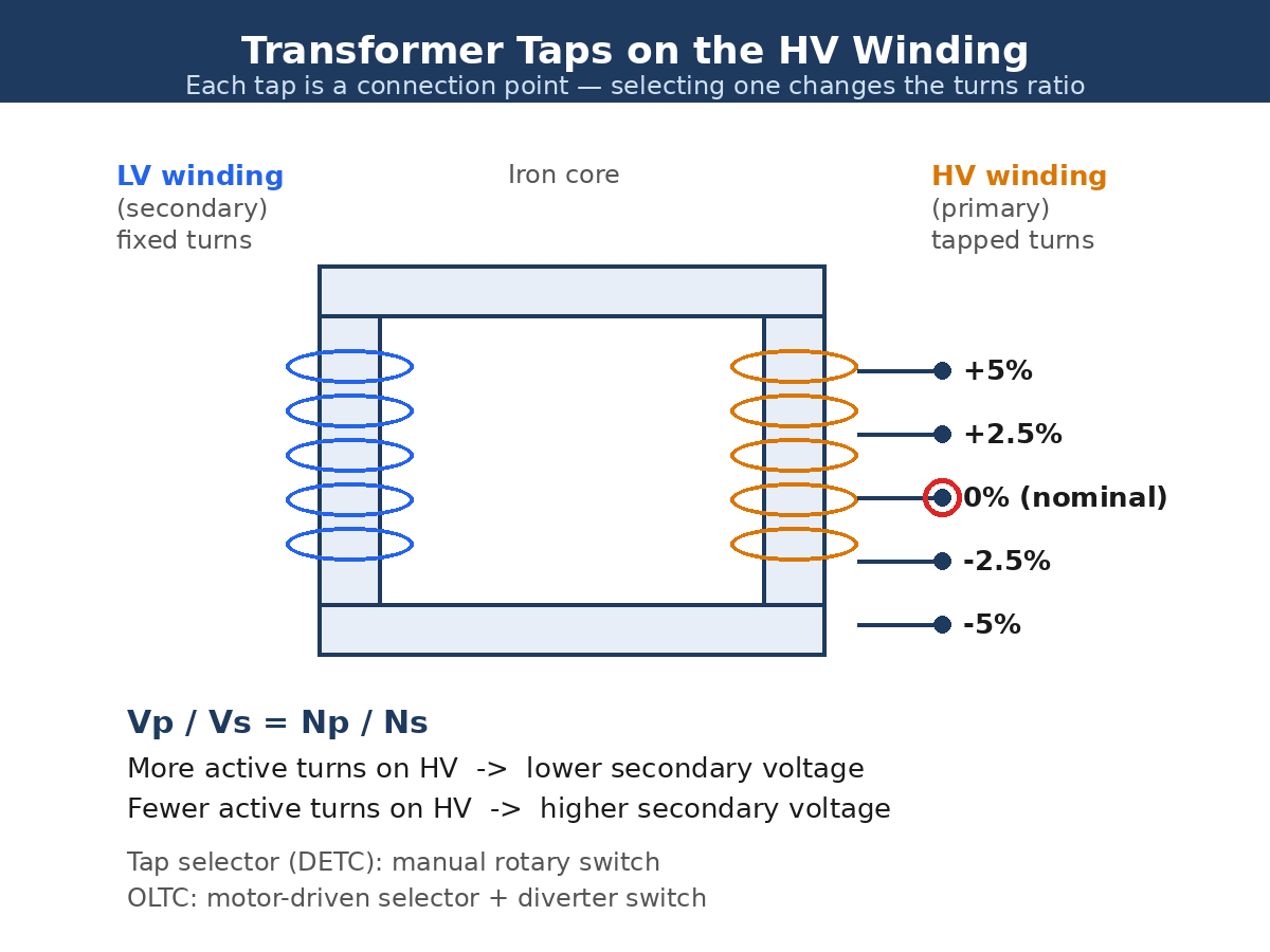
A transformer changes voltage according to its turns ratio: Vp / Vs = Np / Ns, where Vp and Vs are the primary and secondary voltages and Np and Ns are the numbers of turns on each winding. A tap is simply an extra connection point brought out from the winding at a known number of turns. By moving the winding connection from one tap to another, you change the number of active turns — and therefore the turns ratio and the output voltage — without rewinding anything.
Taps are almost always placed on the high-voltage winding, for two practical reasons: the HV current is lower, so the tap switch contacts can be smaller, and a given percentage change in turns is easier to arrange on the winding that has the most turns. A tap marked +5% means the winding has 5% more turns active at that position; selecting it lowers the secondary voltage, because the same primary voltage is now spread over more turns. Conversely, a −5% tap has fewer active turns and raises the secondary voltage. That sign convention catches many beginners out, so it is worth memorizing: plus tap, lower output; minus tap, higher output.
The De-Energized Tap Changer (DETC)
A de-energized tap changer — DETC, also called an off-circuit tap changer (OCTC) or no-load tap changer (NLTC) — is a simple mechanical selector switch connected to the winding taps. It is operated by hand, usually with a rotary handle on the transformer tank or by moving a jumper link, and it has no mechanism for interrupting current. That is why it can only be operated when the transformer is completely de-energized, isolated, and locked out. The name “no-load” must not be read as permission to operate it while the transformer is still energized — even at no load, the tap contacts would draw an arc when opened under voltage.
The standard DETC arrangement on distribution and substation transformers is four taps at +2.5%, +5%, −2.5%, and −5% of rated voltage, as specified in IEEE C57.12.10, with ±7.5% also available on some units. That gives five positions in total including nominal. Because each change needs a planned outage, a DETC is used for seasonal or commissioning adjustments — setting the voltage once to suit a feeder’s long-term conditions, then leaving it alone for months. It is cheap, has almost no moving parts to maintain, and cannot fail in a way that interrupts supply, which is why the great majority of distribution transformers carry a DETC and nothing else.
Changing a DETC setting is a deliberate job: de-energize the transformer, verify it is dead, apply lockout-tagout, move the selector to the new tap, confirm the position against the nameplate, and re-energize. Getting the position wrong — or worse, leaving the selector between taps — can leave the transformer with a poor contact that overheats under load, so the position is always checked twice before re-energizing.
The On-Load Tap Changer (OLTC)
An on-load tap changer changes taps while the transformer remains energized and carrying full load current, with no interruption to supply. That is a much harder engineering problem, because moving a contact between two taps while current flows would either break the circuit — causing an arc and a supply interruption — or briefly short-circuit the winding section between the two taps. The OLTC solves it with a two-part mechanism: a selector that preselects the next tap, and a diverter switch that transfers the load current, using a transition resistor or reactor to bridge the two taps for a few milliseconds.
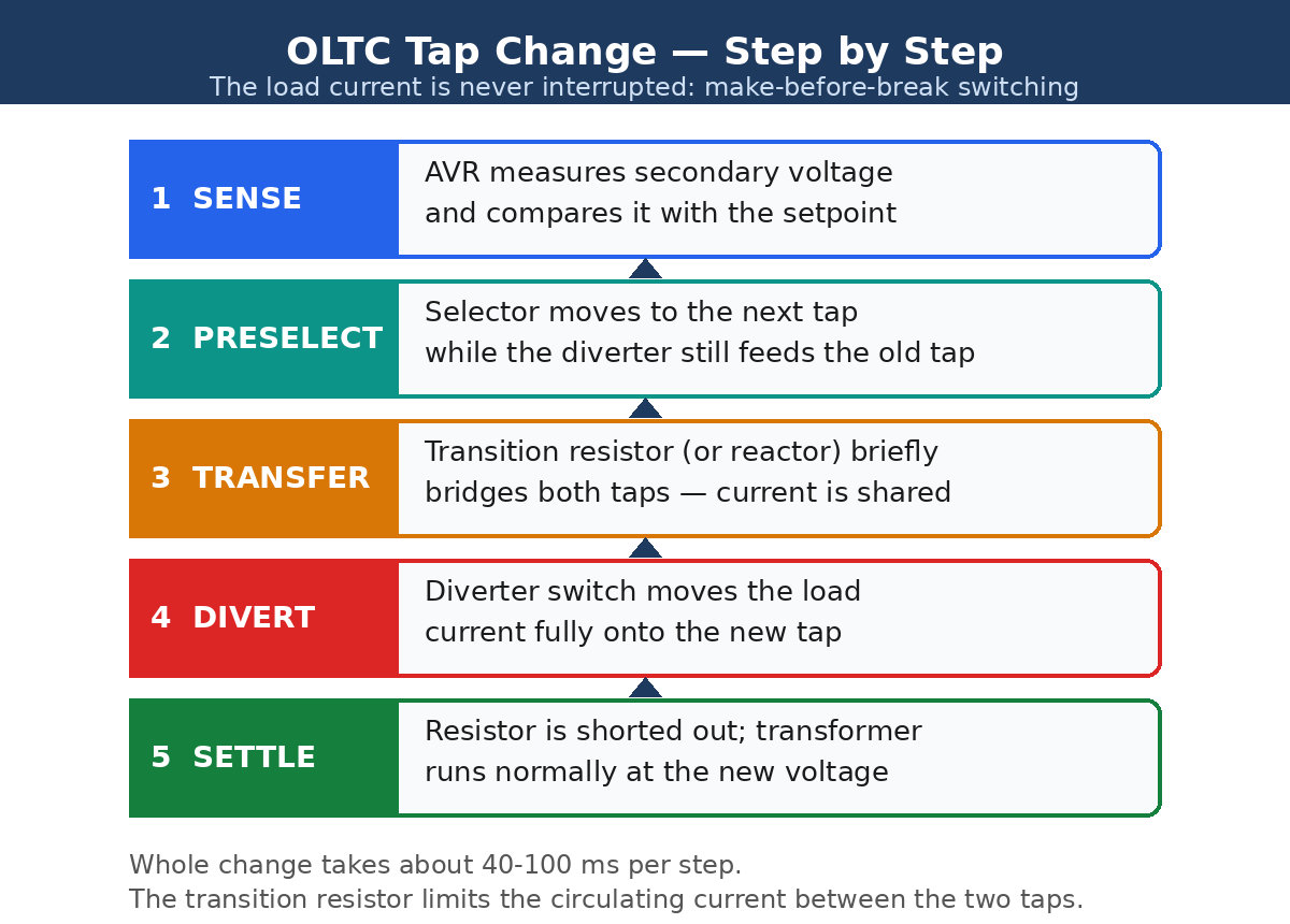
The sequence runs like this. First, the automatic voltage regulator (AVR) measures the secondary voltage and compares it with a setpoint — typically 1.00 per unit on a 120 V control base — and if the deviation exceeds a set bandwidth for longer than a time delay, it orders a tap change. The selector moves to the next tap while the diverter still feeds the old one. The diverter then transfers the current through the transition resistor, which briefly connects both taps and limits the circulating current between them to a safe value. Finally the diverter lands fully on the new tap and the resistor is shorted out. The whole change takes about 40–100 ms per step, and the load never sees an interruption.
OLTCs come in resistor type and reactor type, covered by IEEE C57.131 and IEC 60214-1. The resistor type is the most common worldwide: compact, fast, and well suited to the frequent switching of distribution and sub-transmission transformers. The reactor type uses a center-tapped preventive autotransformer instead of a resistor and is found mainly on large North American power transformers. Either way, the OLTC is the most maintenance-intensive part of a power transformer — its contacts wear with every operation, its oil degrades from arcing, and it is statistically the single most common source of transformer failure, which is why OLTC condition monitoring and oil filtration are routine parts of substation maintenance.
OLTC vs DETC: Side-by-Side Comparison
| Feature | OLTC | DETC |
| Operates under load | Yes — taps change while energized | No — transformer must be de-energized |
| Power interruption | None | Planned outage required |
| Voltage regulation | Continuous, automatic (AVR) | Fixed, manual, infrequent |
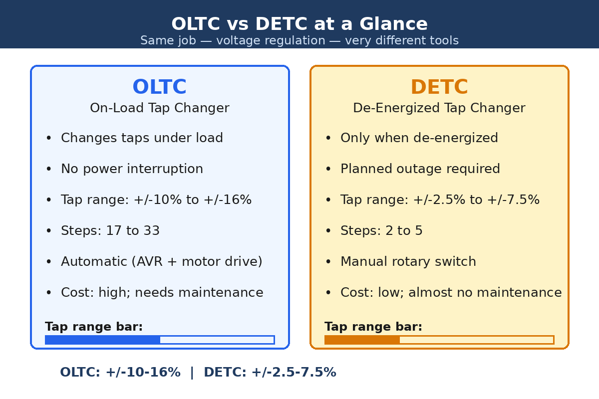
| Typical tap range | ±10% to ±16% | ±2.5% to ±7.5% |
| Number of steps | 17 to 33 positions | 2 to 5 positions |
| Step size | About 1% to 1.67% per step | 2.5% per step |
| Control | Automatic voltage regulator + motor drive | Manual rotary switch or jumper |
| Switching device | Selector + diverter switch + transition resistor/reactor | Simple mechanical selector |
| Cost | High — a large share of transformer price | Low |
| Maintenance | Regular — contacts, oil, drive mechanism | Almost none |
| Typical use | Substation power transformers, grid voltage control | Distribution transformers, seasonal adjustment |
Worked Example: Correcting a Low Secondary Voltage
Take an 11 kV / 433 V distribution transformer on its nominal tap, with a turns ratio of 11,000 / 433 = 25.4. Suppose the primary voltage has fallen to 10.5 kV — about 4.5% low — because of heavy loading upstream. On the nominal tap the secondary becomes 10,500 / 25.4 = 413 V, which is nearly 5% low and will cause problems for motors and lighting.
The fix is the −5% tap. At that tap the HV winding has 5% fewer active turns, so the effective ratio becomes 25.4 × 0.95 = 24.1, and the secondary recovers to 10,500 / 24.1 = 435 V — essentially back to nominal. The +5% tap would have made things worse, dropping the secondary to about 394 V. This is the calculation a field engineer runs before touching the selector, and it is also exactly what the AVR does automatically, many times a day, on an OLTC-equipped substation transformer.
Note what the tap changer cannot do: it cannot fix a voltage drop that happens after the transformer, along the feeder itself, and it cannot raise the voltage above what the tap range allows. If the primary falls by more than the tap range — say 15% low on a ±10% OLTC — the secondary stays low and the problem must be fixed upstream, for example by switching in a capacitor bank or reconfiguring the network. Tap changers regulate the transformer; they do not create voltage that is not there.
Automatic Voltage Regulation and Line Drop Compensation
On an OLTC transformer, the AVR does more than hold the local bus voltage at a setpoint. With line drop compensation (LDC), the controller biases its measured voltage by an amount proportional to the load current, using programmed resistance and reactance settings, so that it regulates the voltage at a remote “load center” down the feeder rather than at the transformer terminals. As load grows, the feeder voltage drop grows, and the AVR raises the tap to compensate — keeping the far end of the feeder inside the ANSI C84.1 voltage limits (typically 114–126 V on a 120 V base) even as conditions change.
The AVR also applies a time delay — typically 30–120 seconds — before ordering a tap change, so that a brief voltage dip from a motor start or a fault does not trigger a useless tap operation. Each operation wears the diverter contacts slightly, so unnecessary switching is avoided. Modern AVRs log every operation, and utilities schedule contact inspections after a set number of operations — commonly tens of thousands — or when dissolved-gas analysis of the OLTC oil shows rising acetylene from arcing.
Where Each Type Is Used
- DETC: pole-mounted and pad-mounted distribution transformers, small industrial transformers, and anywhere the voltage is stable enough that a twice-a-year seasonal adjustment is enough. Also standard on auto-transformers used for fixed-ratio voltage correction.
- OLTC: grid substation power transformers, generator step-up transformers, furnace and rectifier transformers, and any installation where the load or the supply voltage varies through the day. In the US, OLTCs are standard on transmission and sub-transmission transformers and increasingly common on large distribution substations feeding solar and EV loads.
- Both together: many large power transformers carry an OLTC for day-to-day regulation and a DETC on a separate winding for coarse range selection — the DETC sets the overall band at commissioning and the OLTC fine-tunes within it.
When specifying a transformer, the tap changer decision is a loading and cost decision, not an afterthought: the tap range must cover the worst expected supply variation, the step size must be fine enough to hold voltage within limits, and the OLTC’s through-current rating must cover the transformer’s full load. The kVA-to-kW relationship sets the current the tap changer must switch, so the transformer’s rating and its tap changer are always specified together.
Frequently Asked Questions
What is the difference between OLTC and DETC?
An OLTC (on-load tap changer) changes taps while the transformer is energized and carrying load, giving continuous automatic voltage regulation with no interruption. A DETC (de-energized tap changer) can only be moved while the transformer is out of service, so it is used for infrequent manual adjustments such as seasonal voltage correction.
Can a DETC be operated while the transformer is energized?
No. A DETC has no arc-interrupting mechanism, so operating it under voltage — even at no load — would draw a dangerous arc across the contacts and damage the switch and the winding. The transformer must be de-energized, isolated, and locked out before the selector is moved.
What does a +5% tap do to the output voltage?
It lowers the output voltage. A +5% tap adds 5% more turns to the HV winding, which increases the turns ratio and reduces the secondary voltage by about 5%. To raise a low secondary voltage you select a minus tap, such as −5%.
How many tap positions does an OLTC have?
Typically 17 to 33 positions, covering a range of about ±10% to ±16% in steps of roughly 1% to 1.67%. A common arrangement is 17 positions over ±10% (1.25% per step) or 33 positions over ±16% (1% per step). A DETC, by contrast, usually has only 5 positions: nominal plus ±2.5% and ±5%.
Why is the OLTC the most common cause of transformer failure?
Because it is the only part of the transformer that moves under load. Every tap change involves arcing contacts, a motor drive, and oil that degrades with each operation. Regular maintenance — contact inspection, oil filtering, and dissolved-gas analysis — is essential, and many utilities now fit online OLTC monitors that count operations and watch for abnormal switching times.
Conclusion
A tap changer is a transformer’s built-in voltage trim. The DETC does the job simply and cheaply with a manual selector that needs an outage — right for distribution transformers and seasonal correction. The OLTC does it continuously and automatically with a selector, a diverter switch, and a transition resistor, holding the secondary voltage steady while the load never notices — right for substation power transformers, at the price of complexity and maintenance. Whichever type is fitted, the rule is the same: the tap changes the turns ratio, the turns ratio sets the voltage, and a minus tap raises the output while a plus tap lowers it. For a detailed treatment of tap changers in distribution service, including line drop compensation and coordination with distributed generation, see the EEPower guide to on- and off-load tap changers.