Imagine a power station supplying electricity to a city located about 150 kilometers away. The transmission line is much longer than a short distribution line but not long enough to be classified as a long transmission line. In such situations, engineers cannot ignore the effect of line capacitance because it begins to influence voltage regulation, current flow, and power transmission efficiency. This is where the Medium Line Model (π Model & T Model) becomes important.
Medium transmission lines are widely used in modern power systems. Accurate analysis of these lines helps engineers design reliable networks, reduce losses, and maintain stable voltage levels. Electrical students and technicians must understand these models because they bridge the gap between simple short-line analysis and complex long-line calculations.
In this article, you will learn the Medium Line Model working principle, its types, components, advantages, disadvantages, applications, comparison with other transmission line models, selection guidelines, troubleshooting methods, and future trends. The concepts are explained in simple English so beginners can easily understand how medium transmission lines are represented and analyzed in real-world power systems.
What is Medium Line Model (π Model & T Model)?
The Medium Line Model (π Model & T Model) is a method used to represent and analyze medium-length transmission lines in electrical power systems.
A transmission line is generally classified as a medium transmission line when its length is approximately between 80 km and 250 km.
Unlike short transmission lines, medium transmission lines have noticeable capacitance effects. Therefore, resistance, inductive reactance, and capacitance must all be considered during analysis.
Simple Definition
A Medium Line Model is a transmission line representation that includes:
- Line resistance (R)
- Line reactance (X)
- Line capacitance (C)
to accurately predict transmission line performance.
Practical Example
Suppose electricity is transmitted from a generating station to a city located 180 km away. Because the distance is significant, line capacitance affects the voltage profile. Engineers use either the π Model or T Model to calculate voltage regulation and transmission efficiency.
Medium Line Model Working Principle
The Medium Line Model working principle is based on representing the actual electrical characteristics of a transmission line through equivalent circuit components.
Step-by-Step Working
- Electrical power is supplied from the sending end.
- Current flows through line resistance and reactance.
- The line capacitance draws charging current.
- Voltage drops occur because of resistance and reactance.
- The receiving-end voltage is determined after considering all effects.
Simple Analogy
Imagine water flowing through a long pipeline.
- Pipe resistance represents electrical resistance.
- Pipe bends represent reactance.
- Side storage tanks connected to the pipe represent capacitance.
These storage tanks affect water flow just as capacitance affects current and voltage in a transmission line.
Why Capacitance Matters
In medium transmission lines:
- Voltage distribution changes.
- Charging current becomes noticeable.
- Power factor is affected.
- Voltage regulation calculations become more accurate.
Ignoring capacitance would lead to inaccurate results.
Types / Classification
Medium transmission lines are commonly represented using two models.
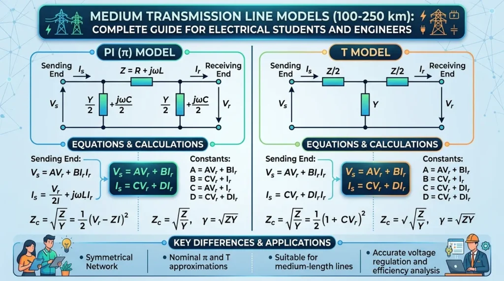
π (Pi) Model
The π Model is one of the most widely used medium line representations.
Its circuit resembles the Greek letter π.
Structure of π Model
- Half capacitance at sending end
- Series impedance in the middle
- Half capacitance at receiving end
Why It Is Popular
- Provides high accuracy
- Easy to analyze mathematically
- Widely used in power system studies
T Model
The T Model is another equivalent representation of a medium transmission line.
Its structure resembles the letter T.
Structure of T Model
- Half impedance on each side
- Total capacitance placed in the center
Advantages of T Model
- Simple physical interpretation
- Useful for educational purposes
- Suitable for certain calculations
Difference Between π Model and T Model
Both models represent the same transmission line.
The difference lies only in how the impedance and capacitance are arranged.
Both provide nearly identical results under normal operating conditions.
Main Components
The Medium Line Model contains several important electrical components.
Resistance (R)
Resistance opposes current flow.
Functions
- Causes power loss
- Generates heat
- Reduces efficiency
Reactance (X)
Reactance opposes changes in current.
Functions
- Produces voltage drop
- Influences power transfer
- Affects system stability
Capacitance (C)
Capacitance stores electrical energy in an electric field.
Functions
- Produces charging current
- Affects voltage profile
- Improves power factor under some conditions
Sending End
The source side of the transmission line.
Functions
- Delivers electrical power
- Maintains transmission voltage
Receiving End
The load side of the transmission line.
Functions
- Receives electrical energy
- Supplies consumers
Load
Electrical equipment connected at the receiving end.
Functions
- Consumes transmitted power
- Determines current demand
Advantages
Understanding the Medium Line Model advantages and disadvantages helps engineers choose the correct model.
Advantages
- More accurate than Short Line Model
- Includes capacitance effects
- Better voltage regulation analysis
- Suitable for practical transmission systems
- Widely accepted in power engineering
- Supports efficient system planning
- Improves transmission performance calculations
- Useful for educational and industrial applications
Real-World Benefits
- Better voltage control
- Improved network reliability
- More accurate loss estimation
- Enhanced power system design
Disadvantages / Limitations
Although useful, the Medium Line Model has limitations.
Disadvantages
- More complex than Short Line Model
- Requires additional calculations
- Less accurate than Long Line Model for very long distances
- Assumes lumped parameters instead of distributed parameters
- May introduce small approximation errors
Practical Limitation
For transmission lines longer than 250 km, engineers usually prefer Long Line Models because distributed effects become significant.
Applications
The Medium Line Model applications are found throughout modern electrical power systems.
Utility Applications
- Regional power transmission
- Substation interconnections
- Medium-voltage transmission systems
Industrial Applications
- Large industrial complexes
- Manufacturing facilities
- Mining operations
Educational Applications
- Electrical engineering laboratories
- Power system analysis courses
- Technical training programs
Modern Technology Applications
- Power system simulation software
- Smart grid studies
- Voltage regulation analysis
- Network planning projects
Renewable Energy Applications
- Solar farm transmission systems
- Wind farm connections
- Regional renewable energy networks
Comparison Section
Difference Between Short Line Model and Medium Line Model
| Feature | Short Line Model | Medium Line Model |
|---|---|---|
| Length | Up to 80 km | 80–250 km |
| Capacitance | Ignored | Included |
| Accuracy | Moderate | Higher |
| Complexity | Low | Medium |
| Voltage Regulation | Less Accurate | More Accurate |
| Applications | Short systems | Medium systems |
Difference Between π Model and T Model
| Feature | π Model | T Model |
|---|---|---|
| Capacitance Location | Split at both ends | Center |
| Impedance Location | Center | Split on both sides |
| Popularity | Very High | Moderate |
| Industrial Usage | Common | Less Common |
| Educational Value | High | High |
| Accuracy | Excellent | Excellent |
Difference Between Medium Line Model and Long Line Model
| Feature | Medium Line Model | Long Line Model |
|---|---|---|
| Length | 80–250 km | Above 250 km |
| Parameter Representation | Lumped | Distributed |
| Complexity | Moderate | High |
| Calculation Effort | Medium | High |
| Accuracy for Long Lines | Limited | Excellent |
Selection Guide
Choosing the right transmission line model is important for accurate analysis.
Use Short Line Model When
- Line length is below 80 km
- Capacitance is negligible
- Quick calculations are needed
Use Medium Line Model When
- Length is between 80 km and 250 km
- Capacitance affects performance
- Better accuracy is required
Use Long Line Model When
- Length exceeds 250 km
- High-voltage transmission is involved
- Maximum accuracy is required
Choosing Between π Model and T Model
For most practical engineering studies:
- π Model is preferred
- T Model is useful for learning and specific analyses
Tips for Beginners
- Always determine transmission line length first.
- Check operating voltage level.
- Consider required calculation accuracy.
- Use π Model whenever industry-standard results are needed.
Common Problems & Solutions
Why are calculated voltages inaccurate?
Possible Cause:
Capacitance effects may have been ignored.
Solution:
Use the Medium Line Model instead of the Short Line Model.
Why is voltage regulation higher than expected?
Possible Cause:
Incorrect impedance values.
Solution:
Verify resistance and reactance data.
Why are simulation results different from actual values?
Possible Cause:
Parameter assumptions may be incorrect.
Solution:
Use accurate transmission line measurements.
Which model should I use: π Model or T Model?
Answer:
Both are acceptable. The π Model is generally preferred in practical power system studies.
Can Medium Line Models analyze long transmission lines?
Answer:
No. Long transmission lines require distributed parameter models.
Future Trends
Power transmission technology continues to evolve.
Smart Grid Development
Future power systems will use real-time monitoring to improve voltage regulation and transmission efficiency.
Advanced Simulation Tools
Modern software can analyze complex transmission networks with greater accuracy.
Renewable Energy Integration
More renewable energy sources require improved transmission system modeling.
Digital Twin Technology
Virtual replicas of transmission systems help engineers predict performance before implementation.
High-Voltage Transmission Expansion
Growing electricity demand is driving the development of larger and more efficient transmission networks.
Despite these advances, the Medium Line Model remains an essential engineering tool because it provides a strong foundation for understanding transmission line behavior.
Conclusion
The Medium Line Model (π Model & T Model) plays a vital role in transmission line analysis. Unlike the Short Line Model, it considers capacitance effects, making it more accurate for transmission lines between 80 km and 250 km. Both the π Model and T Model represent the same physical system but arrange impedance and capacitance differently. Understanding the Medium Line Model working principle helps engineers calculate voltage regulation, efficiency, and power flow with greater accuracy. Although it is more complex than the Short Line Model, it remains practical, reliable, and widely used in power system studies. By mastering these concepts, students and engineers gain a strong foundation for advanced transmission line analysis and modern power system design.