
Imagine switching on a light at home. Electricity leaves the source, travels through the wiring, passes through the lamp, and returns through the circuit. This complete path is an electrical loop. If the path is broken, the lamp cannot operate.
The loop meaning is important because electrical systems depend on complete paths for current to flow. Students often hear terms such as current loop, control loop, ground loop, feedback loop, and loop circuit. Although these terms sound similar, they describe different electrical concepts.
Understanding loops helps beginners read circuit diagrams, troubleshoot wiring, understand control systems, and work safely with electrical equipment. It also gives engineers a foundation for studying circuit analysis, automation, instrumentation, and power systems.
In this guide, you will learn what a loop means in electrical engineering, how an electrical loop works, its major types, important components, advantages and limitations, practical applications, and common problems. You will also learn the difference between loop and circuit, how to select the right loop arrangement, and how modern technology is changing loop-based electrical systems.
2. What Is Loop Meaning?
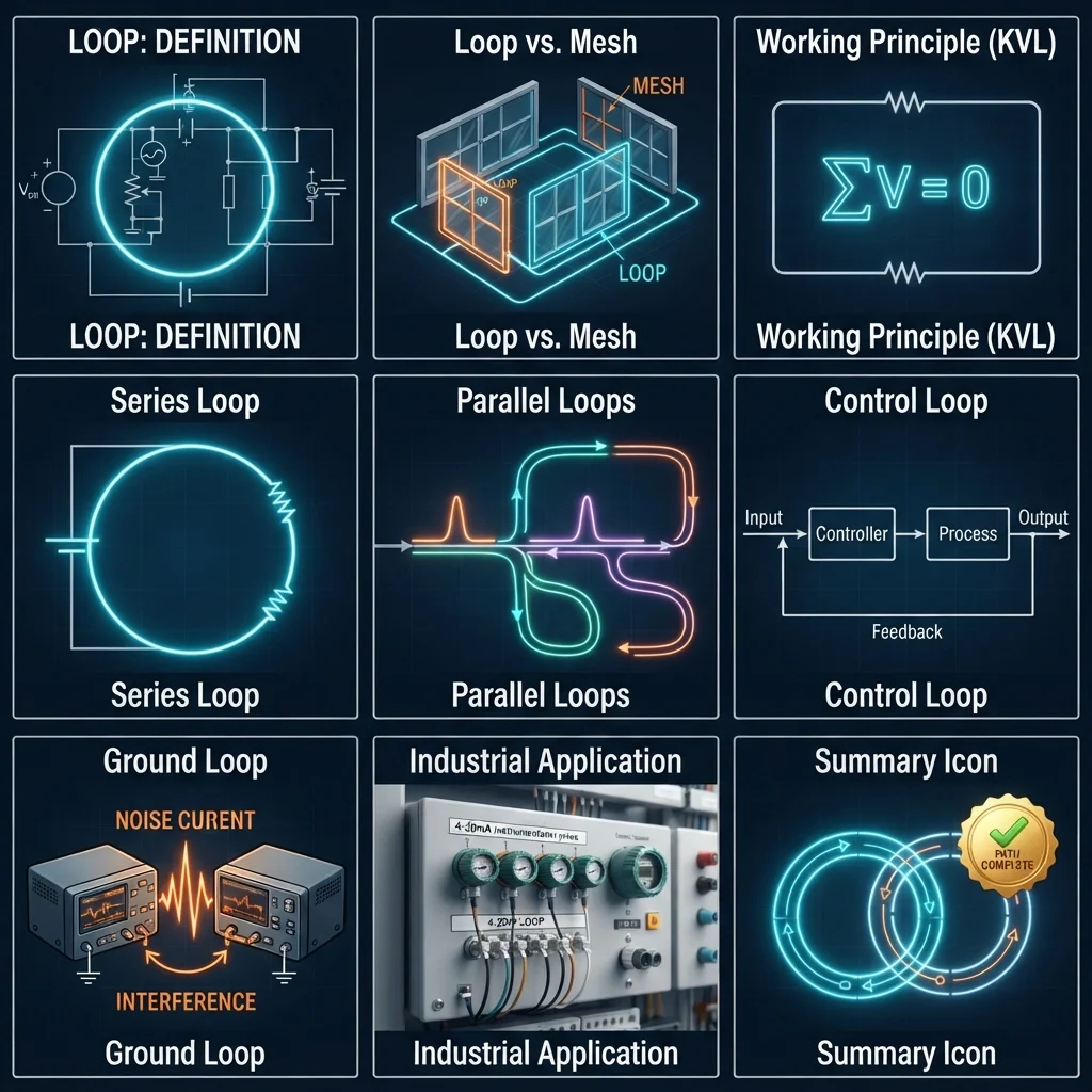
In electrical engineering, a loop is a continuous path through which electrical current can flow or a closed path used for analysis, control, signaling, or measurement.
In simple words:
A loop is a closed path that starts at a point, follows a path, and returns to the starting point.
The exact meaning depends on the application.
For example, in a simple DC circuit:
Battery → Switch → Lamp → Battery
This forms a closed electrical loop.
When the switch is closed, current can flow through the complete path. When the switch is open, the path is broken and current stops.
Practical Example
Consider a battery connected to a small lamp.
The circuit contains:
- Battery
- Wires
- Switch
- Lamp
When the switch closes, current travels around the complete path.
When the switch opens, there is a gap in the path.
This simple example explains the basic loop meaning in electrical systems.
Loop in Circuit Analysis
The word “loop” also has a specific meaning in circuit analysis.
A loop is a closed path in a circuit that can be used to apply electrical laws, especially Kirchhoff’s Voltage Law (KVL).
Engineers can move around a closed loop and add voltage rises and drops to analyze the circuit.
3. Loop Working Principle
The loop working principle depends on creating a complete path for electrical energy, signals, or control information.
Let’s understand it step by step.
Step 1: A Source Provides Energy
A source provides electrical energy.
Examples include:
- Battery
- Generator
- Power supply
- Transformer output
The source creates a voltage difference that can drive current through a suitable closed path.
Step 2: The Path Is Connected
Conductors connect the source to the load or other electrical components.
A complete path is required for normal current flow in a basic circuit.
Step 3: The Load Uses Electrical Energy
The load converts electrical energy into another form.
For example:
- A lamp produces light.
- A motor produces mechanical movement.
- A heater produces heat.
- An electronic circuit processes signals.
Step 4: Current Returns to the Source
In a simple closed circuit, current returns through the remaining part of the loop to the source.
The complete path allows continuous operation.
Step 5: A Break Stops Normal Operation
If a switch opens or a conductor breaks, the loop becomes incomplete.
Current stops in the affected path.
This is why an open circuit is often used to turn equipment off.
Easy Analogy
Think about a circular road.
A car can travel continuously if the road forms a complete circle.
If a section of the road is removed, the car cannot complete the journey.
An electrical loop works in a similar basic way. A complete path allows current or a signal to travel around the intended path.
Loop in a Control System
A control loop works differently from a simple power loop.
A control system may:
- Measure a process.
- Compare the measurement with a target.
- Calculate an error.
- Adjust an output.
- Measure the result again.
This creates a continuous feedback process.
4. Types / Classification of Loops
Electrical engineers use the word “loop” in several ways.
4.1 Electrical Current Loop
A current loop is a closed electrical path through which current flows.
A basic example is:
Source → Load → Return path → Source
Current loops are fundamental to electrical circuit operation.
4.2 Control Loop
A control loop is used to automatically control a process.
For example, a temperature control system may contain:
- Temperature sensor
- Controller
- Heater
- Process
- Feedback signal
The sensor measures temperature and sends information to the controller.
The controller then adjusts the heater.
This process repeats continuously.
4.3 Feedback Loop
A feedback loop sends information from the output back toward the control system.
There are two major forms.
Positive Feedback
Positive feedback reinforces the original change.
It is used in specific electronic and control applications, such as oscillators.
Negative Feedback
Negative feedback reduces the difference between the desired output and actual output.
It is widely used for stable control.
Examples include:
- Temperature control
- Motor speed control
- Voltage regulation
- Industrial process control
4.4 Ground Loop
A ground loop can occur when equipment has multiple unintended grounding paths.
This can create unwanted circulating currents or electrical noise.
Ground loops can be a problem in:
- Audio systems
- Instrumentation
- Communication equipment
- Control systems
Proper grounding and bonding design helps prevent these problems.
4.5 4–20 mA Current Loop
The 4–20 mA loop is a widely used industrial signaling method.
A sensor can represent a measured value using current.
Typically:
- 4 mA = lower measurement
- 20 mA = upper measurement
For example, a pressure transmitter may use 4–20 mA to communicate pressure to a PLC or control system.
One important benefit is that the system can detect certain wiring faults because 0 mA can indicate a problem rather than a normal low measurement.
4.6 Loop in Circuit Analysis
In circuit analysis, engineers identify closed paths called loops.
Voltage changes around a closed loop can be analyzed using Kirchhoff’s Voltage Law.
For an ideal closed loop:
Sum of voltage rises and voltage drops = 0
This method is useful when analyzing complex electrical networks.
5. Main Components of an Electrical Loop
The components depend on the type of loop, but several parts are common.
Power Source
The source provides electrical energy.
Examples:
- Battery
- DC power supply
- Generator
- AC supply
Conductors
Conductors provide the path between components.
Copper and aluminum are common conductor materials.
Load
The load consumes electrical energy.
Examples include:
- Motor
- Lamp
- Heater
- Solenoid
Switch
A switch opens or closes the electrical path.
A closed switch completes the path, while an open switch breaks it.
Sensor
Sensors are important in control loops.
They measure physical quantities such as:
- Temperature
- Pressure
- Level
- Flow
- Speed
Controller
A controller processes information and determines the required control action.
Examples include:
- PLC
- PID controller
- Microcontroller
- Industrial control system
Feedback Path
The feedback path sends information from the output or process back to the controller.
This allows the system to respond to changes.
Protection Devices
Electrical loops may also contain:
- Fuses
- Circuit breakers
- Overload relays
- Protective relays
These devices help protect equipment and conductors from abnormal conditions.
6. Loop Advantages
Properly designed loops provide several practical benefits.
- Complete current path: A basic loop allows current to flow through connected equipment.
- Easy troubleshooting: Technicians can follow the path to find an open connection or faulty component.
- Reliable control: Feedback loops can automatically maintain process conditions.
- Better monitoring: Current loops allow sensors to transmit measurements over practical distances.
- Simple circuit analysis: Closed loops can be analyzed using electrical laws.
- Automation support: Control loops are fundamental to industrial automation.
- Fault detection: Some loop arrangements make certain wiring faults easier to identify.
- Continuous operation: Closed control loops can monitor and adjust equipment continuously.
These benefits explain why loops are used across electrical, electronic, and industrial systems.
7. Loop Disadvantages / Limitations
Loops also have limitations.
Broken Loop
A single open connection can stop a basic current path.
This makes proper connections important.
Wiring Problems
Long wiring runs can introduce:
- Voltage drop
- Electrical noise
- Resistance
- Signal loss
Ground Loop Noise
Unwanted ground paths can cause noise in sensitive systems.
This is especially important in instrumentation and communication systems.
Control Loop Instability
A poorly designed feedback loop may become unstable.
Incorrect controller settings, sensor delays, and process behavior can cause oscillation.
Maintenance Requirements
Sensors, controllers, cables, and other loop components require inspection and maintenance.
Higher System Complexity
Large industrial control loops may contain many devices.
More components can make troubleshooting more difficult without proper documentation.
8. Loop Applications
Loops are used in homes, industry, electronics, automation, and modern technology.
Home Applications
Basic electrical loops are found in:
- Lighting circuits
- Fan circuits
- Doorbells
- Battery-powered devices
- Appliance circuits
For example, a light circuit uses a complete electrical path between the supply and lamp.
Industrial Applications
Industrial facilities use loops extensively.
Common examples include:
- Motor control
- Temperature control
- Pressure control
- Flow control
- Level control
- Process automation
- Machine safety systems
A chemical process, for example, may use a temperature sensor connected to a controller. The controller can adjust a heater based on the measured temperature.
Instrumentation
4–20 mA loops are widely used for transmitting measurements from field instruments to control equipment.
Examples include:
- Pressure transmitters
- Temperature transmitters
- Flow transmitters
- Level transmitters
Automation
PLC systems use control loops to monitor and control machines.
A typical system may be:
Sensor → PLC → Output device → Machine → Sensor
This creates a feedback loop.
Modern Technology
Loop-based systems are also important in:
- Smart factories
- Building automation
- Robotics
- Renewable energy
- Battery management
- HVAC control
- Industrial IoT
- Energy monitoring
9. Difference Between Loop and Circuit
The terms loop and circuit are related, but they are not always interchangeable.
| Feature | Loop | Circuit |
|---|---|---|
| Basic meaning | Closed path | Complete electrical system/path |
| Main focus | Path or closed route | Overall electrical arrangement |
| Can include components | Yes | Yes |
| Used in circuit analysis | Yes | Yes |
| Used in control systems | Yes | Yes |
| Example | Closed path around a network | Complete lighting system |
| Main purpose | Describe a closed path | Describe the entire electrical system |
A circuit can contain one or more loops.
For example, a complex control panel may contain several separate loops within one larger electrical system.
Simple Rule
Think of a circuit as the complete electrical arrangement.
Think of a loop as a closed path within that arrangement.
10. Selection Guide
Choosing a loop arrangement depends on what the system needs to accomplish.
For Basic Electrical Circuits
Check:
- Supply voltage
- Load current
- Conductor size
- Protection
- Switch arrangement
- Circuit length
For Control Systems
Consider:
- Required measurement
- Sensor type
- Control method
- Response speed
- Accuracy
- Environmental conditions
For 4–20 mA Systems
Check:
- Transmitter supply voltage
- Receiver requirements
- Cable length
- Loop resistance
- Number of devices
- Required accuracy
For Industrial Systems
Consider:
- Operating environment
- Electrical noise
- Grounding
- Maintenance access
- Safety requirements
- Future expansion
Tips for Beginners
Start by drawing the loop.
Mark:
- Source
- Conductors
- Components
- Load
- Return path
Then ask:
“Is there a complete path?”
This simple question can solve many basic troubleshooting problems.
11. Common Problems & Solutions
Why Is There No Current in a Loop?
Possible causes include:
- Open switch
- Broken wire
- Blown fuse
- Loose terminal
- Failed component
Solution: Isolate the supply safely and check the circuit section by section using the correct test equipment.
What Causes a Ground Loop?
Multiple unintended grounding paths can create circulating current.
Solution: Review the grounding and bonding arrangement. Do not remove protective earth connections simply to eliminate noise.
Why Does a 4–20 mA Loop Show 0 mA?
Possible causes include:
- Broken wire
- Failed transmitter
- Loss of power
- Loose terminal
- Faulty input device
Solution: A qualified technician can measure loop current and supply voltage to locate the fault.
Why Does a Control Loop Oscillate?
Possible causes include:
- Incorrect controller settings
- Excessive control gain
- Process delay
- Sensor problems
- Incorrect feedback
Solution: Check the sensor, controller settings, and process response before changing control parameters.
Can a Loop Have Multiple Loads?
Yes.
A loop can contain multiple components, depending on its design.
However, voltage, current, resistance, and device compatibility must be considered.
Is a Loop Always a Power Circuit?
No.
A loop can carry:
- Power
- Measurement signals
- Control signals
- Feedback information
Its meaning depends on the application.
12. Future Trends in Loop Technology
Electrical and industrial systems are becoming more intelligent.
Smart Sensors
Modern sensors can provide more than a simple measurement.
They can support:
- Digital communication
- Self-diagnostics
- Fault reporting
- Remote configuration
Digital Control Loops
Traditional analog loops are increasingly being combined with digital controllers.
PLCs, distributed control systems, and industrial computers can process measurements quickly.
Industrial IoT
Industrial IoT connects field devices to larger monitoring systems.
This allows engineers to collect information from many control loops and analyze equipment performance.
Predictive Maintenance
Modern monitoring systems can detect unusual loop behavior before equipment fails.
For example, changing motor current, temperature, or pressure patterns can provide early warning.
Wireless Instrumentation
Wireless sensors can reduce the need for long physical signal cables in some applications.
However, reliability, cybersecurity, power supply, and environmental conditions must be considered.
Smart Buildings
HVAC, lighting, energy management, and security systems increasingly use feedback and control loops.
These systems can automatically adjust operation according to temperature, occupancy, energy demand, and other conditions.
13. Conclusion
The loop meaning in electrical engineering refers to a closed path used for current flow, circuit analysis, signaling, measurement, or control. A simple electrical loop may contain a source, conductors, a load, and a return path. More advanced systems can use feedback loops and 4–20 mA loops for industrial measurement and control.
Understanding the loop working principle is essential for electrical students, technicians, and engineers because loops appear in basic wiring, circuit analysis, automation, instrumentation, and modern industrial systems. It is also important to understand the difference between loop and circuit because a circuit can contain several loops.
Proper loop design improves reliability, troubleshooting, monitoring, and automation. However, wiring faults, ground loops, signal problems, and control instability must be considered. As smart sensors, industrial IoT, digital controllers, and predictive maintenance grow, loop technology will remain an important part of electrical engineering.