Imagine a small power station supplying electricity to a nearby town located only a few kilometers away. The electrical engineers responsible for this system must calculate how much voltage will be lost during transmission and how efficiently power will reach consumers. If the transmission distance is short, using complex transmission line calculations may not be necessary. This is where the Short Line Model becomes extremely useful.
The Short Line Model is one of the most fundamental concepts in power system engineering. It helps engineers analyze the performance of short transmission lines and estimate important parameters such as voltage regulation, current flow, and transmission efficiency. Understanding this model is essential for electrical students, technicians, and engineers because it serves as the foundation for studying more advanced transmission line models.
In this article, you will learn what the Short Line Model is, its working principle, classification, components, advantages, disadvantages, applications, comparisons with other transmission line models, troubleshooting tips, and future developments. By the end, you will have a clear understanding of how the Short Line Model works in practical electrical systems.
What is Short Line Model?
The Short Line Model is a simplified representation of a short electrical transmission line used for power system analysis.
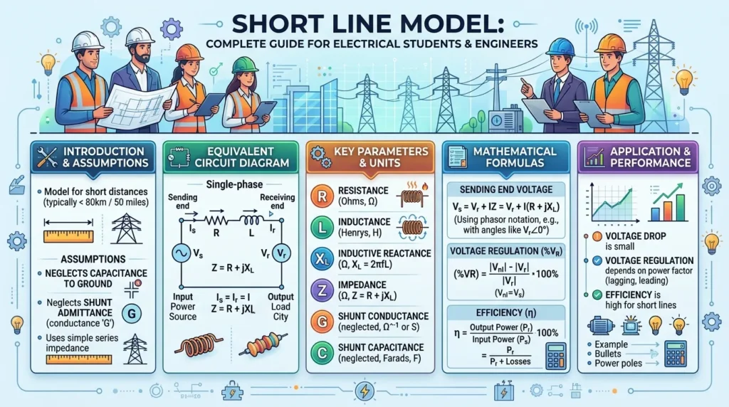
In power engineering, a transmission line is generally classified as a short line when its length is less than approximately 80 kilometers and its operating voltage is below about 20 kV.
For short transmission lines, the effects of line capacitance are very small and can be ignored. Therefore, only the line resistance and inductive reactance are considered during calculations.
Simple Definition
The Short Line Model is a transmission line model in which only series resistance and series reactance are considered, while shunt capacitance is neglected.
Practical Example
Suppose a power plant supplies electricity to a nearby industrial area through a 50-kilometer transmission line. Since the distance is relatively short, engineers can use the Short Line Model to calculate voltage drop and power losses accurately without performing complex calculations.
Short Line Model Working Principle
The Short Line Model working principle is based on the assumption that the transmission line has only resistance and inductive reactance connected in series.
Step-by-Step Working
- Electrical power is generated at the sending end.
- Current flows through the transmission line.
- The line resistance causes power loss in the form of heat.
- The line reactance causes a voltage drop.
- The receiving end receives slightly lower voltage than the sending end.
Simple Analogy
Think of water flowing through a pipe.
- Water flow represents electrical current.
- Pipe friction represents resistance.
- Pipe bends represent reactance.
- Water pressure loss represents voltage drop.
The longer the pipe, the greater the loss. Similarly, resistance and reactance reduce voltage along a transmission line.
Mathematical Representation
The Short Line Model contains:
- Series Resistance (R)
- Series Reactance (X)
The line impedance is:
Z = R + jX
The receiving-end voltage and current are used to calculate the sending-end values.
Types / Classification
Although the Short Line Model itself is a specific transmission line model, transmission lines are generally classified according to their length.
Short Transmission Line
Length: Up to 80 km
Characteristics:
- Capacitance neglected
- Simple calculations
- Used for low-voltage transmission
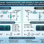
Medium Transmission Line
Length: 80 km to 250 km
Characteristics:
- Capacitance considered
- More accurate calculations
- Used for medium-voltage systems
Long Transmission Line
Length: More than 250 km
Characteristics:
- Capacitance distributed throughout the line
- Complex calculations
- Used for high-voltage transmission
Understanding the difference between short line model and medium line model helps engineers choose the correct analysis method.
Main Components
The Short Line Model contains only a few important components.
Resistance (R)
Resistance opposes current flow.
Functions:
- Causes power loss
- Produces heat
- Reduces transmission efficiency
Inductive Reactance (X)
Reactance opposes changes in current.
Functions:
- Creates voltage drop
- Affects power factor
- Influences system stability
Sending End
The point where electrical power enters the transmission line.
Functions:
- Supplies power
- Maintains transmission voltage
Receiving End
The point where power is delivered to consumers.
Functions:
- Receives electrical energy
- Supplies loads
Load
The electrical equipment consuming power.
Functions:
- Uses transmitted energy
- Determines current flow
Advantages
The Short Line Model advantages and disadvantages are important for understanding where it should be used.
Advantages
- Very simple to understand
- Easy calculations
- Requires less computational effort
- Suitable for educational purposes
- Useful for short-distance power transmission analysis
- Helps students learn transmission line fundamentals
- Provides quick voltage regulation calculations
- Reduces design complexity
Real-World Benefits
- Faster engineering calculations
- Lower design time
- Efficient analysis of local transmission systems
- Useful for preliminary power system studies
Disadvantages / Limitations
Despite its simplicity, the model has limitations.
Disadvantages
- Ignores line capacitance
- Not suitable for medium transmission lines
- Not suitable for long transmission lines
- Reduced accuracy for higher voltages
- Limited use in modern large-scale transmission systems
Practical Limitation
If a transmission line becomes longer than 80 km, ignoring capacitance can lead to significant calculation errors.
Applications
The Short Line Model applications are mainly found in short-distance electrical power systems.
Home Applications
Although not directly used in home wiring, engineers use similar concepts when analyzing short power distribution feeders.
Industrial Applications
- Factory power systems
- Industrial distribution networks
- Manufacturing plants
- Local substations
Utility Applications
- Short-distance power transmission
- Regional distribution systems
- Rural electrical networks
Educational Applications
- Electrical engineering laboratories
- Power system courses
- Engineering training programs
Modern Technology Applications
- Power system simulation software
- Transmission planning studies
- Smart grid educational models
Comparison Section
Difference Between Short Line Model and Medium Line Model
| Feature | Short Line Model | Medium Line Model |
|---|---|---|
| Length | Up to 80 km | 80–250 km |
| Capacitance | Ignored | Considered |
| Complexity | Simple | Moderate |
| Accuracy | Lower for long distances | Higher |
| Calculations | Easy | More complex |
| Applications | Short transmission lines | Medium transmission systems |
Difference Between Short Line Model and Long Line Model
| Feature | Short Line Model | Long Line Model |
|---|---|---|
| Length | Up to 80 km | Above 250 km |
| Capacitance | Ignored | Fully considered |
| Mathematical Complexity | Low | High |
| Accuracy | Suitable for short lines | Suitable for long lines |
| Engineering Use | Basic systems | High-voltage networks |
Selection Guide
Choosing the correct transmission line model is important.
Use Short Line Model When
- Line length is below 80 km
- Voltage level is relatively low
- Quick calculations are required
- Educational analysis is needed
Use Medium Line Model When
- Length exceeds 80 km
- Capacitance becomes significant
- Greater accuracy is required
Use Long Line Model When
- Length exceeds 250 km
- High-voltage transmission is involved
- Detailed system analysis is necessary
Tips for Beginners
- Always check transmission line length first.
- Verify operating voltage.
- Consider required accuracy.
- Use the simplest model that provides acceptable results.
Common Problems & Solutions
Why is the calculated voltage regulation inaccurate?
Possible Cause:
- Capacitance was ignored when it should have been included.
Solution:
- Use the Medium Line Model instead.
Why is power loss higher than expected?
Possible Cause:
- High line resistance.
Solution:
- Use larger conductors or reduce line length.
Why is the receiving-end voltage low?
Possible Cause:
- Excessive voltage drop.
Solution:
- Improve conductor size or system design.
Can the Short Line Model be used for long transmission lines?
Answer:
No. Long transmission lines require more advanced models.
Is capacitance always negligible?
Answer:
Only for short transmission lines.
Future Trends
Power systems are evolving rapidly.
Smart Grid Integration
Modern smart grids use advanced monitoring systems to improve transmission efficiency.
Digital Simulation
Engineers increasingly use software tools for accurate transmission line analysis.
Artificial Intelligence in Power Systems
AI-based systems can predict losses, faults, and voltage regulation more accurately.
Advanced Transmission Technologies
Future transmission systems may rely more on:
- High-voltage DC transmission
- Smart conductors
- Real-time monitoring devices
- Automated control systems
Even with these developments, the Short Line Model will continue to be taught because it provides the foundation for understanding all transmission line analysis techniques.
Conclusion
The Short Line Model is one of the most important concepts in power system engineering. It provides a simple and effective method for analyzing short transmission lines where capacitance effects can be ignored. By considering only resistance and reactance, engineers can calculate voltage drops, transmission efficiency, and power losses with ease. Understanding the Short Line Model working principle helps students build a strong foundation before moving to medium and long transmission line analysis. Although it has limitations, its simplicity, educational value, and practical usefulness make it an essential topic for electrical engineers and technicians. Mastering this model improves power system analysis skills and prepares learners for more advanced transmission engineering concepts.