
Imagine you are working in a small workshop. A motor is running smoothly, lights are on, and everything looks normal. Suddenly, the wires start heating, the breaker trips, and production stops. In another case, a spark flashes inside a panel, followed by a loud sound and immediate power failure.
Both situations are related to electrical faults — but they are not the same. One may be an overload, and the other could be a short circuit.
Understanding Overload vs Short Circuit is very important for electrical students, engineers, and technicians. These faults can damage equipment, cause fires, and risk human safety if not properly controlled.
In this article, you will learn the clear definition of overload and short circuit, their working principles, types, components involved, applications, advantages and disadvantages, and the key difference between overload and short circuit. By the end, you will confidently understand how to identify and protect against these faults in real-world systems.
2. Overload vs Short Circuit: Meaning, Causes, and Examples
Understanding the difference between an overload and a short circuit is essential for electrical safety. Although both conditions result in excessive current flow and can trip protective devices, they occur for different reasons and require different solutions.
What is an Overload?
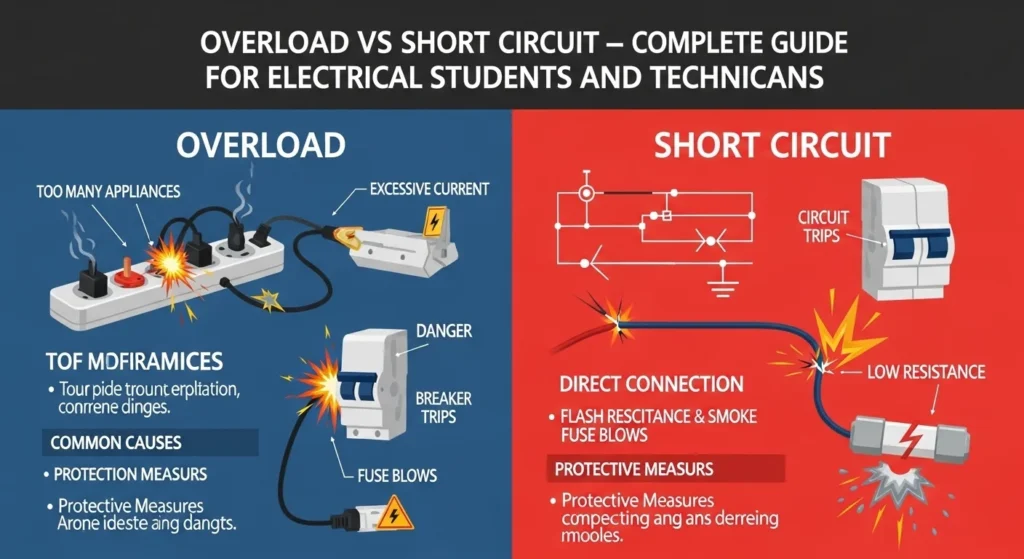
An overload occurs when an electrical circuit or equipment draws more current than its rated capacity for a certain period. In this condition, the circuit itself remains healthy, but the connected load exceeds the safe operating limit.
Simply put, too many electrical devices or a high-power appliance are connected to the same circuit, causing the current to increase gradually.
Practical Example
Imagine plugging an electric heater, microwave, kettle, and air conditioner into the same extension board. Since all these appliances consume high power, the circuit draws more current than it is designed to handle. As a result, the wires begin to heat up, and after a short time, the circuit breaker trips to prevent overheating. This is an overload condition.
Key Characteristics of an Overload
- Current increases gradually.
- Circuit wiring remains intact.
- Heat builds up over time.
- Circuit breaker trips after a delay.
- Usually caused by excessive electrical load.
What is a Short Circuit?
A short circuit occurs when the live (phase) wire comes into direct contact with the neutral or ground wire, creating a path with extremely low resistance.
In simple terms, electricity bypasses the normal load and takes a shortcut, causing an enormous amount of current to flow almost instantly.
Practical Example
Suppose the insulation on two wires becomes damaged and the conductors touch each other. Because there is almost no resistance between them, a massive current flows immediately. This often produces sparks, loud popping sounds, smoke, or even fire if protective devices fail to operate quickly. This is known as a short circuit.
Key Characteristics of a Short Circuit
- Current rises instantly.
- Resistance becomes extremely low.
- Produces sparks and intense heat.
- Circuit breaker trips immediately.
- Can seriously damage electrical equipment.
3. How Overload and Short Circuit Work (Working Principle)
To clearly understand the difference between overload and short circuit, it is important to know how electric current behaves inside a circuit.
According to Ohm’s Law, current depends on the applied voltage and the resistance of the circuit. An increase in electrical load or a sudden drop in resistance changes the current flow in different ways.
Overload Working Principle
Think of an electrical circuit like a water pipe carrying water.
- The pipe has a maximum flow capacity.
- If more water is pushed through the pipe, the pressure increases gradually.
- If the flow continues beyond the safe limit, the pipe overheats or becomes damaged.
The same happens in an electrical circuit during an overload.
Step-by-Step Process
- Electrical appliances are connected to the circuit.
- The total load gradually exceeds the circuit’s rated capacity.
- Current increases above the safe operating limit.
- Electrical wires and equipment begin to generate heat.
- Thermal protection inside the circuit breaker senses the overheating.
- After a short delay, the breaker trips and disconnects the power supply to protect the circuit.
Typical Overload Current:
Overload current is generally 2 to 6 times higher than the normal operating current, depending on the type of equipment and fault condition.
Short Circuit Working Principle
Now imagine that the same water pipe suddenly breaks.
- Water finds the shortest possible path.
- Flow becomes violent and uncontrolled.
- Damage occurs almost immediately.
A short circuit behaves in the same way inside an electrical system.
Step-by-Step Process
- The insulation between conductors fails or two conductors accidentally touch.
- A very low-resistance path is created.
- Electric current rises almost instantly to an extremely high value.
- Powerful magnetic forces, sparks, and intense heat are produced.
- The magnetic mechanism inside the circuit breaker detects the fault immediately.
- The breaker trips within milliseconds to prevent equipment damage and fire.
Typical Short Circuit Current:
Short-circuit current is usually 10 to 100 times greater than the normal operating current, depending on the system voltage and fault impedance.
Quick Comparison
| Feature | Overload | Short Circuit |
|---|---|---|
| Cause | Excessive electrical load | Live wire directly contacts neutral or ground |
| Current Increase | Gradual | Instantaneous |
| Resistance | Normal | Extremely low |
| Heat Generation | Gradual | Extremely high and immediate |
| Breaker Operation | Trips after a short delay | Trips almost instantly |
| Common Result | Overheating of wires | Sparks, fire risk, equipment damage |
| Typical Current | 2–6× normal current | 10–100× normal current |
This revised version is more comprehensive, easier to read, and better optimized for SEO with descriptive headings, structured subheadings, comparison points, and naturally placed keywords such as Overload vs Short Circuit, working principle, difference between overload and short circuit, and overload current vs short circuit current.
4. Types of Overload and Short Circuit
Both overload and short circuit faults can occur in different forms depending on their cause and the electrical system involved. Understanding these types helps in selecting the right protective devices and troubleshooting electrical faults effectively.
Types of Overload
An overload occurs when electrical equipment draws more current than its rated capacity without creating a direct fault between conductors. The following are the most common types of overload.
1. Thermal Overload
A thermal overload occurs when equipment carries excessive current for a prolonged period, causing the temperature of wires, motors, or electrical components to rise gradually.
This is the most common type of overload in electric motors and industrial machines. To protect against thermal overload, thermal overload relays or circuit breakers are commonly used.
Common Causes
- Running a motor beyond its rated load
- Continuous operation under heavy load
- Poor ventilation causing heat buildup
- High ambient temperature
Example
An electric motor driving a conveyor belt with excessive weight operates above its rated capacity. The motor overheats, and the thermal overload relay disconnects the power to prevent damage.
2. Mechanical Overload
A mechanical overload occurs when the mechanical load connected to a motor becomes too heavy or the moving parts become jammed. As a result, the motor must produce more torque, causing it to draw excessive current.
Common Causes
- Jammed conveyor belts
- Blocked pumps
- Seized bearings
- Overloaded compressors
Example
A water pump becomes blocked by debris. Since the impeller cannot rotate freely, the motor draws more current and eventually trips the overload protection.
3. Temporary Overload
A temporary overload is a short-duration increase in current that occurs during normal operation. Unlike continuous overloads, temporary overloads usually do not damage equipment because they last only a few seconds.
Most electrical motors draw a high starting current before reaching their normal operating speed.
Common Causes
- Motor starting current
- Transformer energization
- Short-duration heavy loads
- Sudden changes in operating conditions
Example
An induction motor may draw 5 to 7 times its rated current for a few seconds during startup before returning to normal current.
Types of Short Circuit
A short circuit occurs when an unintended low-resistance path allows excessive current to flow. Different types of short circuits can occur depending on which conductors come into contact.
1. Line-to-Line (L-L) Short Circuit
A line-to-line short circuit occurs when two phase conductors accidentally touch each other.
This type of fault commonly occurs due to damaged insulation, loose wiring, or cable failure.
Common Causes
- Damaged cable insulation
- Loose electrical connections
- Moisture inside electrical panels
- Mechanical damage to cables
Example
In a three-phase system, the R phase wire accidentally touches the Y phase wire, producing a large fault current.
2. Line-to-Neutral (L-N) Short Circuit
A line-to-neutral short circuit occurs when the live (phase) conductor directly contacts the neutral conductor.
This type of fault is common in residential wiring and household electrical appliances.
Common Causes
- Damaged appliance wiring
- Broken insulation
- Incorrect wiring during installation
Example
Inside an electric heater, a damaged wire touches the neutral conductor, causing the circuit breaker to trip instantly.
3. Line-to-Ground (L-G) Short Circuit
A line-to-ground short circuit, also called an earth fault, occurs when the live conductor comes into contact with the grounded metal body of equipment or directly touches the earth.
This type of fault is particularly dangerous because it can create an electric shock hazard.
Common Causes
- Damaged insulation
- Moisture or water ingress
- Faulty electrical equipment
- Broken grounding insulation
Example
The live wire inside a washing machine touches its metal body. Since the body is grounded, a fault current flows to earth and the protective device disconnects the power supply.
4. Three-Phase (L-L-L) Short Circuit
A three-phase short circuit occurs when all three phase conductors come into contact simultaneously.
This is one of the most severe electrical faults because it produces the highest fault current and can cause extensive damage if not cleared immediately.
Common Causes
- Major insulation failure
- Busbar faults
- Switchgear failure
- Serious equipment damage
Example
Inside an industrial switchgear panel, all three busbars accidentally touch each other due to insulation failure, creating a massive fault current that trips the protection system instantly.
Quick Comparison of Overload and Short Circuit Types
| Overload Types | Short Circuit Types |
|---|---|
| Thermal Overload | Line-to-Line (L-L) Short Circuit |
| Mechanical Overload | Line-to-Neutral (L-N) Short Circuit |
| Temporary Overload | Line-to-Ground (L-G) Short Circuit |
| Electrical Overload (General Circuit Overload) | Three-Phase (L-L-L) Short Circuit |
This updated section is more comprehensive, SEO-friendly, and beginner-friendly while naturally incorporating keywords like types of overload, types of short circuit, thermal overload, mechanical overload, line-to-line short circuit, and line-to-ground fault.
5. Main Protective Components Used for Overload and Short Circuit Protection
Electrical systems rely on various protective devices to detect and interrupt abnormal current conditions before they damage equipment or create safety hazards. Each component has a specific function and works together to provide complete protection against overload and short circuit faults.
1. Miniature Circuit Breaker (MCB)
A Miniature Circuit Breaker (MCB) is commonly used in residential and commercial electrical installations to protect low-current circuits.
The MCB automatically disconnects the power supply when it detects an overload or short circuit.
Functions
- Detects overload and short-circuit faults
- Trips automatically when current exceeds the safe limit
- Protects electrical wiring and connected appliances
- Can be reset after the fault is cleared
Common Applications
- Homes
- Offices
- Lighting circuits
- Socket outlets
2. Molded Case Circuit Breaker (MCCB)
An MCCB is designed for higher current ratings than an MCB and is widely used in commercial and industrial power distribution systems.
Many MCCBs have adjustable trip settings, making them suitable for protecting large electrical loads.
Functions
- Protects against overload and short circuit
- Handles high fault currents
- Provides adjustable protection settings
- Suitable for heavy-duty electrical systems
Common Applications
- Industrial plants
- Distribution panels
- Large motors
- Commercial buildings
3. Fuse
A fuse is one of the simplest and most reliable protective devices. It contains a thin metal element that melts when excessive current flows, permanently opening the circuit.
Unlike circuit breakers, a fuse must be replaced after it operates.
Functions
- Interrupts excessive current quickly
- Protects equipment from severe damage
- Provides reliable short-circuit protection
- Simple and economical solution
Common Applications
- Electronic equipment
- Control circuits
- Household appliances
- Automotive electrical systems
4. Thermal Overload Relay
A thermal overload relay specifically protects electric motors from prolonged overload conditions. It operates based on the heating effect produced by excessive current.
It is important to note that a thermal overload relay does not provide fast short-circuit protection. It is normally used together with an MCB, MCCB, or fuse.
Functions
- Detects motor overload
- Protects motor windings from overheating
- Trips after a time delay during overload
- Prevents insulation damage
Common Applications
- Three-phase induction motors
- Pumps
- Compressors
- Conveyor systems
5. Current Transformer (CT)
A Current Transformer (CT) is used in medium- and high-voltage electrical systems to safely measure large currents.
Instead of carrying the full current, the CT produces a smaller proportional current for measuring instruments and protective relays.
Functions
- Measures high electrical current safely
- Supplies current signals to protection relays
- Enables fault detection in power systems
- Improves the accuracy of electrical measurements
Common Applications
- Substations
- Switchgear panels
- Industrial power systems
- Power monitoring systems
6. Protective Relay
A protective relay continuously monitors electrical conditions and commands the circuit breaker to trip whenever an abnormal condition such as an overload or short circuit is detected.
Modern protection relays are digital, highly accurate, and programmable.
Functions
- Detects electrical faults
- Sends trip signals to circuit breakers
- Protects generators, transformers, motors, and feeders
- Improves overall system reliability
Common Applications
- Power plants
- Electrical substations
- Industrial switchgear
- High-voltage distribution systems
Summary of Protective Components
| Protective Device | Protects Against | Typical Application |
|---|---|---|
| MCB | Overload & Short Circuit | Homes and offices |
| MCCB | Overload & Short Circuit | Commercial and industrial systems |
| Fuse | Mainly Short Circuit and Overcurrent | Electronics and appliances |
| Thermal Overload Relay | Overload Only | Electric motors |
| Current Transformer (CT) | Current Measurement & Protection | Substations and industries |
| Protective Relay | Fault Detection & Trip Control | Power systems and switchgear |
Together, these protective components ensure safe operation, reduce equipment damage, and improve the reliability of electrical systems.
6. Advantages of Understanding Overload and Short Circuit
Understanding the difference between overload and short circuit helps engineers, electricians, and technicians design safer electrical systems and choose the correct protective devices.
Key Advantages
1. Improves Electrical Safety
Knowing how overloads and short circuits occur helps reduce the risk of electric shock, overheating, and electrical fires.
2. Protects Electrical Equipment
Proper protection prevents damage to motors, transformers, cables, generators, switchgear, and household appliances.
3. Prevents Fire Hazards
Early detection and interruption of excessive current minimize overheating and significantly reduce the chances of electrical fires.
4. Increases System Reliability
Well-designed protection systems reduce unexpected faults, resulting in more reliable electrical operation.
5. Reduces Downtime
Quick fault isolation prevents major equipment failures and shortens repair time in industrial and commercial facilities.
6. Extends Equipment Life
Operating electrical equipment within its rated limits reduces thermal stress and increases service life.
7. Helps Select the Correct Protective Devices
Understanding fault characteristics makes it easier to choose the appropriate MCB, MCCB, fuse, overload relay, and protective relay.
8. Simplifies Maintenance and Troubleshooting
Knowing whether a fault is caused by an overload or a short circuit helps technicians diagnose problems more quickly and accurately.
7. Disadvantages and Limitations of Overload and Short Circuit Protection
Although modern protection systems are highly effective, they still have certain limitations. Proper design, installation, and maintenance are essential for achieving maximum protection.
1. Overload Protection May Operate Slowly
Thermal protection devices intentionally delay tripping to avoid unnecessary interruptions caused by temporary overloads.
2. Short Circuit Damage Occurs Very Quickly
A short circuit can generate extremely high fault currents within milliseconds, causing damage before the breaker completely interrupts the circuit.
3. Incorrect Protective Device Ratings
Selecting an MCB, MCCB, or fuse with the wrong rating can lead to nuisance tripping or inadequate protection.
4. Protection Devices Cannot Prevent Every Fault
Protective devices disconnect the power after a fault occurs; they cannot stop insulation failure, moisture ingress, or mechanical damage from happening.
5. High Fault Currents Can Damage Equipment
Even when a circuit breaker trips correctly, the enormous energy released during a severe short circuit may still damage switchgear, cables, busbars, or electrical panels.
6. Regular Maintenance Is Required
Circuit breakers, relays, and protective devices require periodic inspection, testing, and calibration to ensure reliable operation.
7. Additional Protection Increases Cost
Installing advanced protection systems, digital relays, and monitoring equipment improves safety but also increases installation and maintenance costs.
8. Human Errors Can Reduce Protection Effectiveness
Improper wiring, incorrect breaker selection, poor installation practices, or neglected maintenance can reduce the effectiveness of overload and short-circuit protection.
Conclusion: No electrical protection system is completely foolproof. The best protection is achieved through proper system design, correct device selection, quality installation, and regular maintenance.
8. Applications
Home Applications
- MCBs in distribution boards
- Protection of air conditioners and heaters
- Overload protection in refrigerators
Industrial Applications
- Motor protection systems
- Generator protection
- Transformer fault protection
- Power distribution panels
Modern Technology Applications
- Solar inverter protection
- Electric vehicle charging systems
- Smart grid systems
- Data center power protection
Proper understanding of Overload vs Short Circuit applications is critical in modern electrical engineering.
9. Difference Between Overload and Short Circuit (Comparison Table)
Many students ask about the difference between overload and short circuit. Here is a simple comparison:
| Feature | Overload | Short Circuit |
|---|---|---|
| Cause | Excess load | Direct wire contact |
| Current Increase | Gradual | Instant and very high |
| Damage Speed | Slow heating | Immediate damage |
| Sound/Spark | Usually none | Loud spark or flash |
| Breaker Response | Delayed trip | Instant trip |
| Risk Level | Moderate | Very high |
This table clearly explains the difference between overload and short circuit in practical terms.
10. How to Select the Right Protection Device for Overload and Short Circuit
Choosing the correct protection device is essential for ensuring the safety, reliability, and efficiency of any electrical system. A properly selected protective device prevents equipment damage, minimizes downtime, and reduces the risk of electrical fires and electric shock.
The selection depends on factors such as the equipment’s rated current, system voltage, cable size, fault current level, and the type of electrical load.
Selection Guide for Beginners
If you are working on residential, commercial, or small electrical installations, follow these basic guidelines.
1. Check the Rated Current of the Equipment
Always verify the rated current (Full Load Current or FLC) mentioned on the equipment’s nameplate before selecting a protective device.
Example:
If a motor has a rated current of 20 A, the protective device should be selected based on this value and the manufacturer’s recommendations.
2. Select the Correct Circuit Breaker Rating
Choose an MCB or MCCB with a current rating that matches the expected operating current while allowing for normal starting conditions.
As a general guideline, the breaker rating is often selected 20–25% above the normal operating current where appropriate and in accordance with electrical codes and equipment specifications.
Example:
- Equipment current = 16 A
- Suitable breaker = 20 A (depending on the application and applicable standards)
3. Use a Thermal Overload Relay for Motors
Electric motors require dedicated overload protection because they often draw high starting currents during startup.
A thermal overload relay protects the motor from prolonged overheating but should always be used together with a circuit breaker or fuse for short-circuit protection.
4. Choose the Correct Breaking Capacity
The breaking capacity (interrupting capacity) of a circuit breaker must be greater than the maximum fault current that may occur at the installation point.
If the available fault current exceeds the breaker’s breaking capacity, the breaker may fail to interrupt the fault safely.
5. Match the Protection Device to the Load Type
Different electrical loads require different protective characteristics.
| Load Type | Recommended Protection |
|---|---|
| Lighting circuits | MCB |
| Socket outlets | MCB |
| Electric motors | MCCB + Thermal Overload Relay |
| Industrial machinery | MCCB + Protective Relay |
| Power distribution panels | MCCB + Protective Relay + Current Transformer (CT) |
Selection Guide for Engineers
For industrial, commercial, and power distribution systems, protection selection requires detailed engineering calculations and coordination studies.
1. Calculate the Maximum Fault Current
Determine the prospective short-circuit current at the installation location.
The selected protective device must have an interrupting capacity greater than the calculated fault current.
2. Consider Cable Size and Current-Carrying Capacity
The protective device must protect the cable as well as the connected equipment.
The breaker rating should never exceed the cable’s safe current-carrying capacity.
3. Perform Protection Coordination (Selective Coordination)
Ensure proper coordination between:
- Protective relays
- MCBs
- MCCBs
- Fuses
- Upstream and downstream circuit breakers
Proper coordination ensures that only the faulty section is disconnected, while the rest of the electrical system continues operating.
4. Consider Motor Starting Current
Large motors can draw 5 to 7 times their rated current during startup.
Select protective devices that allow normal starting current while still providing effective overload and short-circuit protection.
5. Verify Voltage and System Type
Select protection devices that match the electrical system, including:
- Single-phase or three-phase supply
- System voltage
- Frequency (50 Hz or 60 Hz)
- Earthing (grounding) system
6. Follow Electrical Standards
Always select and install protective devices according to recognized electrical standards and local regulations.
Common standards include:
- IEC Standards
- NEC (National Electrical Code)
- IEEE Standards
- Local electrical codes and utility requirements
7. Consider Future Load Expansion
If future equipment additions are expected, plan the protection system accordingly while ensuring that all components remain within safe design limits.
Common Mistakes to Avoid
- Selecting an oversized circuit breaker
- Using an underrated breaker with insufficient breaking capacity
- Ignoring motor starting current
- Using incorrect cable sizes
- Failing to coordinate protective devices
- Ignoring short-circuit current calculations
- Skipping periodic testing and maintenance of protection devices
Key Takeaway
Selecting the right overload and short-circuit protection requires balancing equipment safety, cable protection, and reliable system operation. For small installations, choosing the correct breaker rating and overload protection is usually sufficient. For industrial systems, engineers should perform fault current calculations, cable sizing, and protection coordination studies, while ensuring compliance with applicable electrical standards. Proper protection device selection is the foundation of a safe and dependable electrical installation.
11. Common Overload and Short Circuit Problems with Solutions (FAQs)
Electrical faults such as overloads and short circuits are among the most common causes of equipment failure, power interruptions, and electrical fires. Understanding their causes and solutions helps improve safety, reduce downtime, and extend the life of electrical equipment.
Q1: Why does my circuit breaker trip even when the electrical load seems normal?
A circuit breaker may trip even under a normal load due to problems other than excessive current.
Possible Causes
- Loose or damaged electrical connections
- A weak or aging circuit breaker
- Faulty electrical appliances
- Hidden short circuit or earth fault
- Incorrect breaker rating
- Moisture inside electrical equipment
Solution
- Inspect all wiring and terminals for loose connections.
- Test the connected appliances.
- Verify that the breaker rating matches the circuit load.
- Replace a faulty or worn-out circuit breaker if necessary.
- If the problem continues, have the circuit inspected by a qualified electrician.
Q2: Can an overload cause an electrical fire?
Yes. A continuous overload causes electrical wires and equipment to overheat. Over time, excessive heat damages cable insulation, which can lead to short circuits, melting insulation, or electrical fires.
How to Prevent It
- Avoid connecting too many appliances to one circuit.
- Use correctly rated MCBs or MCCBs.
- Install thermal overload protection for motors.
- Replace damaged or undersized cables.
- Perform regular electrical inspections.
Q3: Is a short circuit more dangerous than an overload?
Yes. A short circuit is generally much more dangerous because it produces an extremely high fault current almost instantly.
Unlike an overload, which develops gradually, a short circuit can generate intense heat, powerful electrical arcs, and large magnetic forces within milliseconds.
Possible Effects
- Equipment damage
- Electrical arc flash
- Fire hazards
- Explosion of switchgear
- Severe electric shock risk
For this reason, circuit breakers and fuses are designed to interrupt short-circuit currents as quickly as possible.
Q4: Why does my motor trip after running for some time?
If a motor operates normally at startup but trips after several minutes, the most likely cause is a thermal overload.
Possible Causes
- Mechanical overload
- Jammed bearings or rotating parts
- Blocked pump or conveyor
- Low supply voltage
- Poor ventilation
- High ambient temperature
- Incorrect overload relay setting
Solution
- Reduce the mechanical load.
- Check bearings and moving parts.
- Clean ventilation openings.
- Verify the supply voltage.
- Adjust the overload relay according to the motor’s rated current.
- Inspect the motor for overheating or internal faults.
Q5: How can I reduce the risk of a short circuit?
The risk of a short circuit can be greatly reduced by following good electrical installation and maintenance practices.
Best Practices
- Use high-quality insulated cables.
- Replace damaged or cracked wiring immediately.
- Route cables properly to avoid mechanical damage.
- Tighten all electrical terminals securely.
- Keep electrical panels clean and dry.
- Install correctly rated circuit breakers and fuses.
- Ensure proper grounding (earthing) of electrical equipment.
- Avoid overloading extension cords and power outlets.
- Perform periodic inspection and preventive maintenance.
Q6: What is the difference between an overload trip and a short-circuit trip?
An overload trip occurs when equipment draws slightly more current than its rated value for an extended period. The breaker usually trips after a short delay because heat gradually builds up.
A short-circuit trip occurs when a very large current flows instantly due to a fault between conductors. The breaker trips almost immediately to prevent severe damage.
Q7: Can a fuse and a circuit breaker be used together?
Yes. In many industrial and commercial installations, fuses and circuit breakers are used together to provide better protection. The fuse offers very fast short-circuit protection, while the circuit breaker provides overload protection and convenient switching.
Q8: How often should electrical protection devices be inspected?
Protective devices should be inspected and tested regularly as part of a preventive maintenance program.
General recommendations include:
- Residential systems: Every 3–5 years or after major electrical work.
- Commercial buildings: Annual inspections.
- Industrial facilities: Routine inspections and testing according to maintenance schedules and applicable standards.
Maintenance Tips to Prevent Overload and Short Circuit Faults
Regular preventive maintenance is the most effective way to reduce electrical faults and improve system reliability.
- Inspect cables for damage or worn insulation.
- Tighten loose electrical connections.
- Test circuit breakers and protective relays periodically.
- Keep electrical panels clean, dry, and free from dust.
- Avoid overloading electrical circuits.
- Replace damaged components immediately.
- Verify proper grounding (earthing).
- Schedule routine preventive maintenance and thermal inspections.
Key Takeaway: Most overloads and short circuits can be prevented through proper equipment selection, quality installation, correct protective devices, and regular maintenance. Early detection and timely maintenance not only improve electrical safety but also reduce repair costs and unexpected downtime.
12. Future Trends in Overload and Short Circuit Protection
Electrical protection systems are rapidly evolving with the advancement of smart technologies, automation, Artificial Intelligence (AI), and the Internet of Things (IoT). Modern protection devices not only detect overloads and short circuits but also monitor electrical systems in real time, predict failures, and help prevent costly downtime.
The future of electrical protection is focused on intelligent, connected, and predictive systems that improve safety, reliability, and energy efficiency.
1. Smart Circuit Breakers
Smart circuit breakers are the next generation of traditional MCBs and MCCBs. They continuously monitor electrical parameters such as current, voltage, power consumption, and temperature.
Unlike conventional breakers, smart breakers can communicate with smartphones, computers, or Building Management Systems (BMS), allowing users to monitor electrical circuits remotely.
Key Features
- Real-time current and voltage monitoring
- Instant overload and short-circuit alerts
- Remote ON/OFF control
- Energy consumption tracking
- Fault history and event logging
- Integration with smart home and industrial automation systems
Applications
- Smart homes
- Commercial buildings
- Data centers
- Industrial facilities
2. IoT-Based Electrical Protection
The Internet of Things (IoT) is transforming electrical protection by connecting protective devices to cloud-based monitoring platforms.
IoT-enabled systems continuously collect electrical data and send instant notifications whenever abnormal conditions such as overloads, short circuits, overheating, or voltage fluctuations are detected.
Benefits
- Remote monitoring from anywhere
- Instant fault notifications via mobile apps
- Predictive maintenance
- Reduced downtime
- Improved energy management
- Centralized monitoring of multiple electrical systems
Applications
- Smart factories
- Renewable energy plants
- Commercial buildings
- Utility power networks
3. Arc Fault Detection Devices (AFDDs)
An Arc Fault Detection Device (AFDD) is designed to detect dangerous electrical arcing that conventional circuit breakers and fuses may not identify.
Electrical arcs can occur because of damaged cables, loose connections, worn insulation, or deteriorated electrical components. These arcs generate intense heat and are one of the leading causes of electrical fires.
Key Features
- Detects hazardous electrical arcs
- Prevents electrical fires
- Provides early fault detection
- Works alongside MCBs and RCCBs
- Improves overall electrical safety
Applications
- Residential buildings
- Hospitals
- Schools
- Hotels
- Wooden structures
- High-risk commercial installations
4. AI-Based Fault Prediction
Artificial Intelligence (AI) is revolutionizing electrical protection by analyzing large amounts of operational data to identify patterns and predict potential failures before they occur.
Instead of reacting after a fault happens, AI systems can warn maintenance teams about developing overload conditions, insulation deterioration, or abnormal equipment behavior.
Benefits
- Predicts overload conditions before failure
- Detects abnormal current patterns
- Reduces unexpected equipment failures
- Improves maintenance planning
- Extends equipment life
- Minimizes maintenance costs
Applications
- Industrial automation
- Smart power grids
- Manufacturing plants
- Electrical substations
5. Digital Protective Relays
Traditional electromechanical relays are increasingly being replaced by digital (numerical) protective relays.
These intelligent devices provide highly accurate fault detection, event recording, communication capabilities, and programmable protection settings.
Advantages
- Faster fault detection
- High measurement accuracy
- Remote configuration
- Self-diagnostic functions
- Event and fault recording
- Integration with SCADA systems
6. Smart Grid Protection Systems
Modern smart grids use advanced sensors, communication networks, and automated protection devices to improve the reliability of electrical power systems.
Smart grids can automatically isolate faulty sections while maintaining power to unaffected areas, reducing outage durations and improving service continuity.
Benefits
- Automatic fault isolation
- Self-healing power networks
- Faster power restoration
- Improved grid reliability
- Better integration of renewable energy
7. Predictive Maintenance Using Sensors
Modern electrical systems are increasingly equipped with intelligent sensors that continuously monitor:
- Current
- Voltage
- Temperature
- Vibration
- Insulation resistance
- Power quality
These sensors help identify developing faults long before they become serious failures.
Benefits
- Early fault detection
- Reduced maintenance costs
- Improved equipment reliability
- Extended asset life
- Fewer unexpected shutdowns
8. Cloud-Based Electrical Monitoring
Cloud technology enables engineers to access electrical system data from anywhere using computers or mobile devices.
Historical data, fault records, and real-time operating conditions can be analyzed to improve maintenance planning and system performance.
Advantages
- Remote access
- Automatic data storage
- Performance analytics
- Instant fault notifications
- Improved decision-making
Future Outlook
The future of overload and short-circuit protection is moving toward fully intelligent electrical systems that combine AI, IoT, cloud computing, smart sensors, and digital protection devices. These technologies will make electrical installations safer, more reliable, and easier to maintain by detecting faults earlier, predicting equipment failures, and enabling remote monitoring and automated protection.
As industries continue to adopt Industry 4.0, smart grids, and digital automation, intelligent protection systems will become the standard for residential, commercial, and industrial electrical installations.
13. Conclusion
Understanding Overload vs Short Circuit is fundamental for every electrical student and technician. Overload is a gradual increase in current due to excess load, while a short circuit is a sudden, high-current fault caused by direct wire contact. Both can damage equipment and create safety hazards.
We explored the working principle, types, applications, comparison, and selection guide. We also discussed the difference between overload and short circuit in a simple table for clarity.
As a junior engineer, always remember: proper protection design saves lives, equipment, and money. Continue learning, practice calculations, and inspect systems carefully. Electrical safety is not optional — it is a professional responsibility.