Imagine you are running a large water pump in an industrial plant. You press a small push button, and suddenly the motor starts running. You are not directly handling the high current motor circuit. Instead, a small control signal is activating a device that safely switches the power supply. That device is called a contactor.
A contactor is one of the most important components in electrical control and industrial automation systems. It is widely used for switching motors, heaters, lighting systems, and heavy electrical loads.
Understanding what is a contactor is essential for electrical students, engineers, technicians, and beginners. Contactors provide safe and reliable control of high-power circuits using low-power signals.
In this article, you will learn contactor working principle, types of contactors, contactor applications, advantages and disadvantages, and selection tips — explained in simple and practical language.
Contactor
A contactor is an electrically controlled switch used to turn a power circuit ON or OFF. It is widely used in electrical systems to control motors, lighting, heating equipment, and other high-power loads. Unlike a manual switch, a contactor operates automatically using an electromagnetic coil, making it very useful in industrial and automation applications. It allows a low-power control circuit to safely control a high-power electrical device.
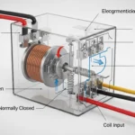
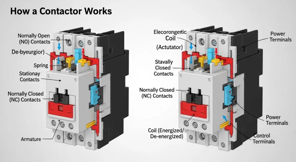
The working principle of a contactor is based on electromagnetism. When voltage is applied to the coil, it creates a magnetic field that pulls the movable contacts toward the fixed contacts, closing the circuit and allowing current to flow to the load. When the coil is de-energized, a spring mechanism pushes the contacts back to their original position, opening the circuit and stopping the current flow. This process allows frequent switching without manual effort.
Contactors consist of several important parts, including the coil, main contacts, auxiliary contacts, and arc suppression system. The main contacts carry the load current, while auxiliary contacts are used for control and signaling purposes. The arc suppression system helps reduce sparks that occur when contacts open or close, improving safety and extending the life of the device.
One of the main advantages of a contactor is its ability to handle high current loads safely. It is reliable, durable, and suitable for frequent switching operations. Contactors also provide remote control capability, which is essential in automation systems. However, they also have some limitations. They can produce noise during operation, require proper maintenance, and may wear out over time due to contact arcing.
Overall, a contactor is an essential component in modern electrical systems. It improves safety, efficiency, and control in both industrial and commercial applications, making it a key device for engineers and technicians.
What is a Contactor?
A contactor is an electrically controlled switching device used to make or break an electrical power circuit.
Simple Explanation
- A contactor works like a relay but is designed for high-power loads.
- It is mainly used in motor control circuits.
- It operates using an electromagnetic coil.
Practical Example
In an industrial conveyor system, a push button sends a signal to the control circuit. That signal energizes the contactor coil, and the contactor switches ON the motor supply.
So, when we ask what is a contactor, remember this simple idea:
Contactor is a heavy-duty electrically controlled switch.
Contactor Working Principle
The contactor working principle is based on electromagnetic force.
Let us explain step-by-step.
Control Signal Activation
Control Signal activation is the process of sending and enabling a signal that starts, stops, or regulates a system or device. In modern electrical, electronic, and automation systems, control signals play a very important role. They act like instructions that tell machines what to do, when to do it, and how to do it. Control signal activation is widely used in industries, robotics, communication systems, and smart devices.
In simple terms, a control signal is a small electrical or digital input that triggers a larger action. For example, pressing a switch sends a control signal to turn on a light. In industrial systems, a control signal may activate motors, valves, relays, or sensors. These signals are usually low-power but are used to control high-power equipment safely and efficiently. This makes control systems more reliable and easier to manage.
Control signal activation works through different methods depending on the system. In electrical systems, activation can happen using voltage or current signals. In digital systems, control signals are sent using binary data (0 and 1). In automated systems, programmable logic controllers (PLCs) receive input signals and activate machines based on programmed instructions. In communication systems, control signals help manage data transfer, switching, and synchronization between devices.
One important application of control signal activation is in robotics. Robots use sensors to receive input signals from the environment. These signals are processed, and control signals are activated to move motors or perform tasks. Another example is in power systems, where control signals are used to switch circuit breakers or regulate voltage levels.
Control signal activation is also important in safety systems. Fire alarms, emergency shutdown systems, and security systems all rely on control signals to activate alarms or shut down equipment when needed. Without proper control signals, machines would not respond correctly to user commands or system conditions.
Overall, control signal activation is a key part of modern technology. It ensures that electrical and electronic systems operate in a controlled, safe, and efficient way by converting small input signals into meaningful actions in real-world applications.
- When control voltage is applied, current flows through contactor coil.
Magnetic Field Formation
Magnetic Field formation is the process in which a magnetic field is created around a moving electric charge or a magnetic material. A magnetic field is an invisible force field that can attract or repel certain materials like iron, nickel, and cobalt. It is also responsible for the working of many electrical machines such as motors, generators, transformers, and inductors.
A magnetic field is mainly formed when electric current flows through a conductor. When electrons move through a wire, they create circular magnetic lines around the wire. The strength of this magnetic field depends on the amount of current flowing and the type of material used. If the current increases, the magnetic field becomes stronger. This principle is widely used in electromagnets, where a coil of wire is wrapped around an iron core. When current flows through the coil, it creates a strong magnetic field that can lift heavy metal objects.
Magnetic field formation also occurs in coils called solenoids. A solenoid is a long wire wound in a tight spiral. When electric current passes through it, a uniform magnetic field is produced inside the coil. This is very useful in devices like relays, valves, and electric locks. In rotating machines like electric motors, magnetic fields interact with current-carrying conductors to produce motion. This is the basic principle behind mechanical rotation in electrical systems.
In Electromagnetism, electricity and magnetism are closely linked. A changing magnetic field can also produce electric current, which is the working principle of generators. Similarly, electric current produces magnetic fields, which is the principle behind motors and transformers. This relationship is the foundation of modern electrical engineering.
Magnetic field formation is also important in natural systems. The Earth itself acts like a giant magnet with a magnetic field that protects the planet from harmful solar radiation. This field is formed by the movement of molten iron in the Earth’s core.
Overall, magnetic field formation is a fundamental concept in physics and electrical engineering. It helps explain how electrical energy is converted into mechanical energy and how many modern devices operate efficiently and safely.
- Coil current produces magnetic field.
Armature Movement
Armature movement is the process in which the rotating or moving part of an electrical machine turns due to electromagnetic forces. The armature is a key component in devices like electric motors and generators. It carries current and interacts with a magnetic field to produce motion or electrical energy. Armature movement is the basic principle behind many modern electrical machines used in homes, industries, and transportation systems.
In an electric motor, armature movement occurs when electric current flows through the armature windings. This current interacts with the magnetic field created by permanent magnets or electromagnets. According to the principle of Electromagnetism, a force is produced on the current-carrying conductor. This force causes the armature to rotate. As a result, electrical energy is converted into mechanical energy, which can be used to run fans, pumps, machines, and vehicles.
In a generator, the process is reversed. Instead of receiving electrical energy, the armature is rotated by an external mechanical force such as a turbine or engine. As the armature moves within a magnetic field, it cuts magnetic lines of force. This action induces an electric current in the armature windings. This is based on the principle of electromagnetic induction. Thus, mechanical energy is converted into electrical energy.
The speed and efficiency of armature movement depend on several factors, including the strength of the magnetic field, the amount of current flowing, and the design of the machine. Stronger magnetic fields and higher current generally produce greater torque and faster rotation. Engineers design armatures carefully to reduce energy losses caused by friction, heat, and resistance.
Armature movement is widely used in DC motors, AC motors, alternators, and generators. It plays a vital role in powering industrial machines, household appliances, electric vehicles, and power generation systems. Without proper armature movement, electrical machines would not be able to convert energy efficiently.
Overall, armature movement is a fundamental concept in electrical engineering that enables the conversion between electrical and mechanical energy, making it essential for modern technology and industrial development.
- Magnetic field pulls the movable contact assembly.
Contact Closing
Electrical Contact closing is the process in which two electrical contacts come together to complete a circuit and allow electric current to flow. When contacts are open, the circuit is broken and no current flows. When contacts close, the circuit becomes complete, and electricity can pass through the system. Contact closing is a basic but very important concept in electrical and electronic systems.
Contact closing is widely used in switches, relays, circuit breakers, contactors, and control systems. For example, when you press a light switch, the internal contacts close and the light turns on. In industrial systems, relays use small control signals to close contacts that operate high-power machines. This allows safe control of large electrical loads using low-power signals.
The process of contact closing happens quickly and must be reliable. In many systems, electromagnetic force is used to close contacts. When current flows through a coil, it creates a magnetic field that pulls the contact arm and closes the circuit. This principle is used in relays and contactors. In manual switches, physical force from a user closes the contacts directly.
During contact closing, a small spark may occur due to sudden current flow. This is called arcing and can damage contacts over time. To reduce this effect, engineers use materials like silver alloys and protective devices such as arc suppressors. Proper design ensures smooth and safe contact operation.
Contact closing is essential in automation and control systems. It helps machines start, stop, and change operation modes safely. In power systems, circuit breakers use contact closing and opening to protect electrical networks from faults and overloads. In electronic circuits, switches and relays rely on accurate contact closing for correct signal flow.
Overall, contact closing is a fundamental electrical process that enables control, safety, and operation of almost all electrical systems by completing or breaking an electrical circuit when needed.
- Main contacts close and power circuit is connected.
Load Operation
Electrical Load operation refers to the working condition in which electrical power is being consumed by a device or system. In simple terms, a load is anything that uses electricity to perform a function, such as lighting a bulb, running a motor, heating an element, or operating electronic equipment. Load operation is an important concept in electrical engineering because it describes how electrical systems behave when power is actually being used.
During load operation, electrical energy is drawn from a power source and converted into other forms of energy such as light, heat, sound, or mechanical motion. For example, when a fan is switched on, it becomes a load that converts electrical energy into mechanical rotation. Similarly, a heater converts electrical energy into heat, and a speaker converts it into sound. The performance of a system depends on how efficiently it handles different types of loads.
There are different types of loads in electrical systems. Resistive loads include devices like heaters and incandescent bulbs, where voltage and current remain in phase. Inductive loads include motors and transformers, where current lags behind voltage due to magnetic field formation. Capacitive loads include capacitors and electronic circuits, where current leads voltage. Each type of load affects system behavior differently during operation.
Load operation also determines how much current flows in a circuit. When more devices are connected, the load increases, and the system must supply more current. If the load becomes too high, it can cause overheating, voltage drops, or system failure. That is why electrical systems are designed with proper load calculations and safety margins.
In power systems, load operation is carefully monitored to maintain stability. Engineers use instruments like load analyzers and meters to measure power consumption and ensure efficient operation. Proper load management helps reduce energy loss and improves system reliability.
Overall, load operation is a key part of electrical systems because it represents the real working condition where energy is consumed and converted into useful output in homes, industries, and technology systems.
- Motor or load starts running.
Simple Analogy
Think of contactor like a remote-controlled switch:
- Push button = Remote signal
- Coil = Receiver
- Contacts = Switch mechanism
This is contactor working principle in simple terms.
Types / Classification of Contactors
Contactors are classified based on application and design.
AC Contactors
AC Contactor is an electrical switching device used to control high-power alternating current (AC) circuits. It works like a heavy-duty switch that is operated by a low-power control signal. AC contactors are widely used in industrial systems, motor control circuits, air conditioners, pumps, elevators, and automation systems because they can safely handle large electrical loads.
An AC contactor works using an electromagnetic coil. When a control voltage is applied to the coil, it creates a magnetic field. This magnetic field pulls a movable arm and closes the main contacts, allowing current to flow through the circuit. When the control signal is removed, the magnetic field disappears, and a spring mechanism opens the contacts, stopping the current flow. This process is fast, reliable, and repeatable.
AC contactors are designed to handle high current loads without damage. They are different from simple switches because they can operate automatically using control systems like timers, sensors, or programmable logic controllers (PLCs). This makes them very useful in industrial automation where machines need to start and stop frequently.
There are different types of AC contactors based on voltage rating, current capacity, and application. Some are used for single-phase systems, while others are designed for three-phase industrial motors. Many AC contactors also include auxiliary contacts for control circuits and safety interlocking.
One of the main advantages of AC contactors is safety. They allow high-power circuits to be controlled remotely using low-voltage signals, reducing the risk of electric shock. They also improve system efficiency and provide better control over electrical machines. However, they may produce noise during operation and require proper maintenance to ensure long-term reliability.
Overall, AC contactors are essential components in modern electrical and industrial systems, providing safe and efficient switching for high-power AC loads.
- Used in AC power systems.
- Common in motor starters.
- Designed for AC load switching.
DC Contactors
DC Contactor is an electrical switching device used to control high-power direct current (DC) circuits safely and efficiently. It works like an automatic switch that can turn DC power ON or OFF using a low-power control signal. DC contactors are widely used in electric vehicles, battery systems, solar power plants, railway systems, and industrial control equipment.
A DC contactor operates using an electromagnetic coil. When a control voltage is applied, the coil generates a magnetic field that pulls the moving contacts together, closing the circuit and allowing current to flow. When the control signal is removed, a spring mechanism separates the contacts, breaking the circuit and stopping the current flow. This process is fast and reliable, making DC contactors suitable for automatic control systems.
One important challenge in DC contactors is arc formation. Unlike AC, DC current does not naturally cross zero, so when contacts open under load, a strong electric arc can form. This arc can damage the contacts over time. To reduce this problem, DC contactors are designed with special arc suppression techniques such as magnetic blowouts, arc chutes, and high-quality contact materials. These features help extinguish the arc quickly and improve device lifespan.
DC contactors are commonly used in high-voltage battery systems such as electric vehicles (EVs), forklifts, solar energy storage systems, and uninterruptible power supplies (UPS). They are also used in industrial machines where reliable DC switching is required. Many modern DC contactors are compact, fast, and designed for high efficiency and safety.
There are different types of DC contactors based on voltage rating, current capacity, and application. Some are designed for low-voltage battery systems, while others are built for high-voltage industrial or transportation systems. Auxiliary contacts and safety interlocks are often included for better control and monitoring.
Overall, DC contactors are essential components in modern electrical systems, enabling safe and efficient switching of direct current power in a wide range of advanced technologies and energy applications.
- Used in DC circuits.
- Found in battery systems and electric vehicles.
Vacuum Contactors
Vacuum Contactor is an advanced type of electrical switching device used to control high-voltage and high-current circuits safely. In a vacuum contactor, the main switching contacts are sealed inside a vacuum bottle. This vacuum environment prevents air from interfering with the switching process, which greatly reduces arcing and increases the life of the device. Vacuum contactors are widely used in industries, power plants, mining, and heavy electrical systems.
The working principle of a vacuum contactor is based on electromagnetic operation. When a control signal is applied, an electromagnetic coil becomes energized and creates a magnetic field. This field pulls the moving contact toward the fixed contact, closing the circuit and allowing current to flow. When the control signal is removed, a spring mechanism separates the contacts, opening the circuit and stopping the current flow. Because the contacts are inside a vacuum, the arc formed during switching is quickly extinguished.
One of the main advantages of vacuum contactors is their ability to handle frequent switching operations without significant wear and tear. In a vacuum, there is no oxygen or gas to support arcing, so the arc is quickly suppressed. This makes them highly reliable and long-lasting compared to air-based contactors. They also require very little maintenance and offer high safety in demanding electrical environments.
Vacuum contactors are commonly used in medium-voltage applications such as motor control centers, capacitor switching, transformers, and industrial machinery. They are especially useful in applications where frequent switching is required, such as controlling large motors in mining or manufacturing industries. Many modern power systems also use vacuum contactors for efficient and safe operation.
Another important benefit is their compact design and high performance. They can operate in harsh environments, including dust, moisture, and vibration. However, they are generally more expensive than traditional contactors and require careful installation.
Overall, vacuum contactors are a crucial part of modern electrical engineering, providing safe, fast, and reliable switching for high-power applications while minimizing arcing and improving system efficiency.
- Contacts operate inside vacuum chamber.
- High reliability.
- Minimal arc formation.
Magnetic Contactors
Magnetic Contactor is an electrical switching device used to control high-power circuits using a low-power electrical signal. It works on the principle of electromagnetism, where an electromagnet is used to open or close electrical contacts. Magnetic contactors are widely used in industrial automation, motor control, HVAC systems, pumps, elevators, and power distribution systems because they provide safe and reliable switching.
A magnetic contactor consists of three main parts: an electromagnet coil, a set of contacts, and a spring mechanism. When a control voltage is applied to the coil, it creates a magnetic field. This magnetic field pulls the movable contacts toward the fixed contacts, closing the circuit and allowing current to flow. When the control signal is removed, the magnetic field disappears, and the spring pushes the contacts back to their original position, breaking the circuit and stopping the current flow.
Magnetic contactors are designed to handle high electrical loads such as three-phase motors and heavy industrial machines. They are often used in combination with overload relays and protective devices to ensure safe operation. One of their key advantages is that they allow remote and automatic control of electrical equipment, reducing the need for manual switching and improving safety.
These contactors come in different types based on voltage rating, current capacity, and application. They may include auxiliary contacts for control circuits, interlocking systems for safety, and enclosures for environmental protection. Magnetic contactors are commonly used in motor starters to start and stop electric motors safely without causing damage.
One of the major benefits of magnetic contactors is their durability and reliability. Since they use electromagnetic operation, they can perform repeated switching without significant wear. However, they may produce a clicking noise during operation and require proper maintenance for long-term performance.
Overall, magnetic contactors are essential components in modern electrical systems, providing efficient, safe, and automated control of high-power electrical circuits in industrial and commercial applications.
- Most common industrial type.
- Uses electromagnetic coil operation.
Understanding difference between AC contactor and DC contactor is important for beginners.
Main Components of a Contactor
Coil
- Produces magnetic field.
- Acts as control element.
Main Contacts
- Carry load current.
- Usually made of silver alloy material.
Auxiliary Contacts
Two types:
- Normally Open (NO)
- Normally Closed (NC)
Used for control circuit feedback.
Armature
- Mechanical moving part.
- Connects and disconnects contacts.
Spring Mechanism
- Returns armature to initial position.
Each component ensures safe switching operation.
Advantages of Contactor
Let us discuss contactor advantages and disadvantages.
Advantages
- Safe control of high-power circuits
- Remote operation capability
- Suitable for automation systems
- High switching reliability
- Long operational life
- Easy integration with PLC systems
Real-world benefit: Contactors allow operators to control heavy motors safely.
Disadvantages / Limitations
- Mechanical wear over time
- Contact arcing may occur
- Noise during switching
- Requires maintenance
- Higher cost than simple switches
Engineers must consider these limitations during design.
Contactor Applications
Contactor applications are very wide.
Home Applications
- Air conditioner compressors
- Water pump motors
- Heating systems
Industrial Applications
- Motor starter panels
- Conveyor systems
- Industrial automation
- Elevator control
Modern Technology
- Electric vehicle motor control
- Renewable energy systems
- Smart industrial plants
Contactors are essential in heavy electrical switching.
Comparison Section
Difference Between Contactor and Relay
| Feature | Contactor | Relay |
| Load Capacity | High | Low |
| Contact Size | Large | Small |
| Main Use | Motor switching | Signal switching |
| Arc Suppression | Better | Limited |
| Current Rating | High | Low |
This table helps beginners understand the difference between contactor and relay.
Selection Guide
When selecting a contactor:
- Check load current rating
- Check coil voltage rating
- Consider switching frequency
- Check environmental conditions
- Verify contact material quality
Beginner Tips
- Always install overload protection.
- Use proper wiring insulation.
- Follow manufacturer datasheet.
- Provide proper ventilation.
Never oversize or undersize contactor rating.
Common Problems & Solutions
Why does contactor not pull in?
Cause:
- Low control voltage
- Coil damage
Solution:
- Measure coil supply voltage
- Replace coil if faulty
Why do contacts burn?
Cause:
- Excess load current
- Arc formation
Solution:
- Use arc suppressor
- Select proper rating
How to test contactor?
- Check coil resistance
- Test contact continuity
- Inspect mechanical movement
Future Trends
Contactor technology is evolving.
Solid State Switching
Solid State Switching is a modern method of controlling electrical circuits using semiconductor devices instead of mechanical contacts. Unlike traditional switches that use physical movement to open or close a circuit, solid-state switches operate electronically. They use components like transistors, thyristors, and MOSFETs to control the flow of current. This makes switching faster, more reliable, and more durable.
In solid state switching, a small control signal is used to turn the device ON or OFF. When the control signal is activated, the semiconductor device allows current to flow through the circuit. When the signal is removed, the current stops. Because there are no moving parts, there is no mechanical wear and tear. This greatly increases the lifespan of the switching system and reduces maintenance needs.
Solid state switching is widely used in industrial automation, power electronics, communication systems, and consumer electronics. For example, it is used in LED lighting systems, computer power supplies, motor controllers, and temperature control systems. In industries, solid state relays (SSRs) replace mechanical relays to control high-power machines with high speed and precision.
One major advantage of solid state switching is its fast response time. It can switch thousands or even millions of times per second, which is not possible with mechanical switches. It also produces less noise and no sparks during operation, making it safer in sensitive environments. Additionally, it provides better performance in harsh conditions such as vibration, dust, and humidity.
However, solid state switching also has some limitations. It can generate heat during operation and may require heat sinks for cooling. It can also be more expensive than traditional mechanical switches. Despite these drawbacks, its advantages make it essential in modern electronic and electrical systems.
Overall, solid state switching is a key technology in today’s world, enabling efficient, fast, and reliable control of electrical power without mechanical movement, and it is widely used in both small devices and large industrial systems.
- No mechanical movement
- High-speed switching
- Longer life
Smart Automation Systems
Smart Automation System refers to advanced systems that use sensors, controllers, and software to automatically control machines, processes, and devices with minimal human involvement. These systems are designed to improve efficiency, accuracy, safety, and productivity in homes, industries, transportation, and communication networks. Smart automation combines electrical engineering, electronics, and computer technology to create intelligent and self-operating systems.
In a smart automation system, sensors collect real-time data such as temperature, motion, pressure, light, or humidity. This data is sent to a control unit, such as a microcontroller or programmable logic controller (PLC). The controller analyzes the information and makes decisions based on programmed instructions. After processing, control signals are sent to actuators, motors, switches, or other devices to perform specific actions. This entire process happens automatically and continuously.
Smart automation systems are widely used in industrial automation. Factories use these systems to control robotic arms, conveyor belts, and production lines with high precision. In homes, smart automation is used in lighting control, air conditioning systems, security alarms, and smart appliances. These systems can even be controlled remotely using smartphones or the internet, making them part of the Internet of Things (IoT).
One of the key advantages of smart automation systems is increased efficiency. They reduce human effort, save time, and minimize errors. They also improve safety by handling dangerous tasks such as high-voltage operations or chemical processing. In addition, they help reduce energy consumption by optimizing system performance based on real-time conditions.
However, smart automation systems also require proper design, maintenance, and cybersecurity protection. Since many systems are connected to networks, they can be vulnerable to hacking if not properly secured. Despite this, their benefits make them essential in modern technology.
Overall, smart automation systems are transforming the world by making machines and processes more intelligent, responsive, and efficient. They play a major role in modern industry, smart homes, healthcare, transportation, and future digital infrastructure.
- IoT-based motor control
- Remote monitoring
- Predictive maintenance
Renewable Energy Integration
Renewable Energy Integration is the process of connecting clean energy sources like solar, wind, hydro, and biomass into the main electrical power system. It ensures that renewable energy works smoothly with traditional power plants and delivers stable electricity to homes, industries, and cities. As the world moves toward cleaner energy, renewable energy integration has become a key part of modern power systems.
In this system, energy from renewable sources is first generated using technologies like solar panels, wind turbines, and hydroelectric plants. Since these sources are naturally variable, their output can change depending on weather conditions. For example, solar power depends on sunlight, and wind power depends on wind speed. Because of this variation, energy must be carefully managed before it is added to the main grid.
Power electronics devices such as inverters play an important role in renewable energy integration. They convert DC power from solar panels into AC power that can be used in the electrical grid. Control systems monitor voltage, frequency, and load demand to ensure stable power supply. Energy storage systems like batteries are also used to store extra energy and supply it when production is low.
One major challenge of renewable energy integration is maintaining grid stability. Since renewable sources are not constant, sudden changes in power generation can affect voltage and frequency. To solve this, smart grids and automation systems are used to balance supply and demand in real time. Backup power from conventional plants may also be used when needed.
Despite challenges, renewable energy integration offers many benefits. It reduces carbon emissions, decreases dependence on fossil fuels, and supports sustainable development. It also creates new job opportunities in the energy sector and improves energy security for countries.
Overall, renewable energy integration is a vital step toward a cleaner and more sustainable future. It combines advanced technology, smart control systems, and renewable resources to create a reliable and eco-friendly power supply for the modern world.
Contactors are widely used in:
- Solar inverter systems
- Wind power plants
Future contactors will be more intelligent and efficient.
Conclusion
A contactor is a very important switching device used in electrical and industrial automation systems. It allows safe remote control of high-power circuits using low-power signals.
We discussed what is a contactor, contactor working principle, types of contactors, contactor applications, and contactor advantages and disadvantages. We also compared contactor and relay and explained selection guidelines.
For electrical students and junior engineers, understanding contactors is essential for learning motor control and industrial automation.
Focus on practical circuit testing and safety practices. Strong knowledge of contactors helps build a solid foundation in power system and control engineering.
Keep learning and practicing real-world electrical systems.