
Imagine an electrician repairing a home distribution board without proper wiring color identification. If the live, neutral, and earth wires are mixed up, the result can be electric shock, equipment damage, fire hazards, or complete power failure. This is why wiring color codes are extremely important in every electrical system, from small household circuits to large industrial installations.
Wiring color codes help electricians, engineers, and technicians identify the function of each wire quickly and safely. These standardized colors reduce confusion during installation, troubleshooting, maintenance, and repairs. Without proper color coding, electrical work would become dangerous and inefficient.
In this article, you will learn the complete basics of wiring color codes, including their definition, wiring color codes working principle, different standards used around the world, wire classifications, applications, advantages and disadvantages, troubleshooting methods, and future trends. The article is written in simple and easy English so beginners and professionals can understand the topic clearly.
What Are Electrical Wiring Color Codes?
Electrical wiring color codes are standardized colors used to identify the purpose and function of different wires in an electrical circuit. These colors help electricians, electrical technicians, engineers, and maintenance workers quickly identify live, neutral, earth, and control conductors during installation, inspection, testing, and repair work.
The main purpose of wiring color codes is to improve electrical safety and reduce the possibility of incorrect connections. When wires are properly identified, an electrician can understand the basic function of a conductor without having to trace every wire through the entire circuit.
For example, a live conductor carries electrical potential to a load, a neutral conductor normally provides the return path, and a protective earth conductor provides a path for fault current. Correct identification of these conductors is especially important when working inside distribution boards, electrical panels, sockets, switches, motors, and other electrical equipment.
However, wire colors are not exactly the same in every country or installation. Different electrical standards may specify different colors. Older installations may also use wiring colors that differ from modern standards. Therefore, electricians should always follow the applicable local electrical code and verify conductors with suitable test equipment before working on a circuit.
Common Electrical Wire Colors
Some commonly encountered colors include:
- Brown or Red: Often used for the live or line conductor, depending on the electrical standard.
- Blue or Black: Commonly used for the neutral conductor, depending on the wiring system and applicable standard.
- Green or Green/Yellow: Commonly used for the protective earth or grounding conductor.
- Black, Grey, Orange, or Other Colors: May be used for additional phases, switched lines, control circuits, or other functions depending on the applicable wiring standard.
It is important to remember that these colors are not universal. A wire should not be identified by color alone, particularly in an old, modified, or unfamiliar installation.
Why Are Wiring Color Codes Important?
Wiring color codes provide several practical benefits:
- Improve Electrical Safety: Correct identification helps reduce the risk of connecting a live conductor to the wrong terminal.
- Make Installation Easier: Electricians can identify conductors more quickly during wiring work.
- Simplify Troubleshooting: Properly identified wires make it easier to locate faults and trace circuits.
- Reduce Wiring Errors: Standard colors help prevent incorrect connections.
- Support Maintenance: Future technicians can understand the circuit more easily.
- Improve Panel Organization: Correct conductor identification makes electrical panels cleaner and easier to inspect.
Practical Example: Home Electrical Socket
A typical three-wire electrical socket circuit may contain three main conductors:
Live Wire:
The live wire supplies electrical energy from the distribution system to the connected appliance. It is normally the conductor that presents the greatest shock hazard when the circuit is energized.
Neutral Wire:
The neutral wire normally provides the return path for current from the appliance back toward the supply source. Under normal operating conditions, current flows through the load between the live and neutral conductors.
Earth Wire:
The earth or protective conductor is primarily used for safety. It provides a low-impedance path for fault current if a fault causes an exposed conductive part of equipment to become energized.
For example, if an appliance develops an insulation fault and its metal casing becomes energized, the protective earth connection can help provide a fault-current path. This can cause the appropriate protective device, such as a circuit breaker or fuse, to disconnect the supply and reduce the risk of electric shock.
Important Safety Note
Never assume that a wire is safe simply because of its color. Incorrect wiring, old installations, poor modifications, and non-standard practices can result in unexpected conductor identification.
Before touching or disconnecting any conductor:
- Switch off the appropriate power supply.
- Isolate the circuit where required.
- Verify that the circuit is de-energized using a properly rated tester.
- Follow the applicable electrical code and safety procedures.
- Use appropriate personal protective equipment when required.
In short, electrical wiring color codes provide a simple visual identification system for electrical conductors. They make installation, maintenance, and troubleshooting easier, but the actual applicable wiring standard should always be checked before making electrical connections.
Electrical Wiring Color Codes Working Principle
The wiring color codes working principle is based on standardized visual identification. Each conductor in an electrical circuit has a specific purpose, and its assigned color helps electricians and technicians identify that purpose quickly.
Wiring color codes do not control the flow of electricity themselves. Instead, they provide a clear identification system that helps ensure wires are connected to the correct terminals and used for their intended function.
The exact colors can vary according to the country, electrical code, wiring system, and age of the installation. Therefore, technicians should always follow the applicable standard and verify conductors with suitable testing equipment.
Step-by-Step Explanation
1. Electrical Supply Reaches the Circuit
Electrical power comes from a source such as the utility supply, generator, transformer, or distribution panel.
The supply normally includes conductors that provide the required voltage to the electrical load.
2. The Live Wire Supplies the Load
The live or line conductor carries electrical potential from the supply toward the connected device.
For example, when you switch on a lamp, the live conductor provides the electrical supply needed for the lamp to operate.
3. Current Passes Through the Electrical Load
When the circuit is complete, current flows through the connected load.
The load may be:
- Light bulb
- Fan
- Motor
- Heater
- Pump
- Electronic device
The electrical load converts electrical energy into useful output such as light, heat, motion, or electronic operation.
4. The Neutral Provides the Normal Return Path
In a typical single-phase system, the neutral conductor provides the normal return path for current from the load back toward the supply source.
This allows the electrical circuit to operate as intended.
5. The Earth Wire Provides Protection
The protective earth (PE) conductor has a safety function rather than being part of the normal load-current path.
If an insulation fault causes an exposed metal part of equipment to become energized, the protective earth connection can provide a suitable fault-current path. This helps protective devices operate and disconnect the faulty circuit.
Simple Analogy
Think of wiring color codes like traffic signs and road markings.
Different colors and markings help people understand what they should expect and how they should behave.
Similarly, standardized wire colors help electricians identify the intended function of conductors.
For example:
- Live/line color: Identifies a conductor associated with the supply voltage.
- Neutral color: Identifies the neutral conductor in systems where a neutral is provided.
- Green or green/yellow: Commonly identifies the protective earth conductor where required by the applicable standard.
The important point is that the color provides identification, while the electrical design determines how the conductor actually functions in the circuit.
Why Standardization Matters
Standardized wiring colors are important because they create a common identification system for electrical workers.
Without proper identification:
- Electricians could connect conductors incorrectly.
- Maintenance work could become more difficult.
- Troubleshooting could take longer.
- The risk of electric shock could increase.
- Equipment could be damaged by incorrect connections.
- Electrical faults could be harder to identify.
Example of Correct Identification
Consider a simple lighting circuit.
The supply provides the circuit voltage. The live conductor passes through the appropriate switching device and supplies the lamp. The neutral provides the normal return path, while the protective earth is connected to exposed conductive parts where required.
The color of each conductor helps the electrician identify its intended role during installation and maintenance.
However, color alone should never be treated as proof that a conductor is safe or de-energized. A qualified person should verify the circuit using an appropriate, properly rated test instrument before handling conductors.
Key Point to Remember
The basic principle of wiring color codes is:
Identify → Connect correctly → Test → Operate safely → Maintain easily
Therefore, wiring color codes are an important part of electrical installation practice because they make conductor identification faster, reduce wiring errors, and support safer maintenance and troubleshooting.
Types and Classification of Electrical Wiring Color Codes
Electrical wiring color codes can be classified according to the electrical standard, country, type of electrical system, and conductor function. Understanding these classifications is important because wire colors are not identical worldwide.
A color that identifies a live conductor in one wiring system may have a different function in another system. Older installations may also use colors that are different from modern standards.
The following are some of the most commonly encountered wiring color-code systems.
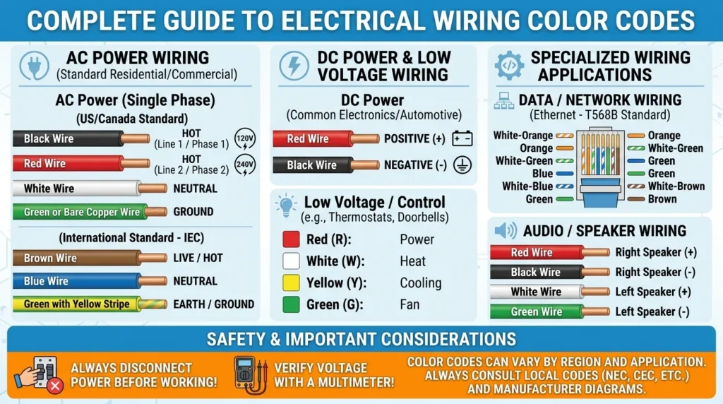
1. IEC Wiring Color Codes
The International Electrotechnical Commission (IEC) publishes international electrical standards that are followed or adopted in many countries.
Modern IEC-based installations commonly use the following conductor identification.
Single-Phase Wiring
In a typical IEC-style single-phase system:
- Brown = Live/Line
- Blue = Neutral
- Green/Yellow = Protective Earth (PE)
Step-by-Step Example
Suppose a single-phase appliance has three conductors:
- The brown conductor is commonly used as the live or line conductor.
- The blue conductor is commonly used as the neutral conductor.
- The green/yellow conductor is used for protective earth.
The live conductor supplies the appliance, the neutral normally provides the return path, and the protective earth provides a safety path during an electrical fault.
Three-Phase Wiring
A common IEC conductor identification for a three-phase system is:
- Brown = L1
- Black = L2
- Grey = L3
- Blue = Neutral
- Green/Yellow = Protective Earth
This arrangement makes it easier to identify the three phase conductors in distribution boards, industrial equipment, and other electrical installations.
Important: The exact conductor identification requirements should always be checked against the electrical standard applicable to the installation.
2. Old UK Wiring Color Codes
Older UK electrical installations used a different color system from the modern IEC-style system.
This is important when working on older buildings because the wiring may not match the colors used in a modern installation.
Old Single-Phase Wiring
Commonly encountered older UK colors were:
- Red = Live
- Black = Neutral
- Green = Earth
For example, an old lighting or socket circuit may contain a red live conductor and a black neutral conductor.
Old Three-Phase Wiring
Older UK three-phase installations commonly used:
- Red = Phase 1
- Yellow = Phase 2
- Blue = Phase 3
- Black = Neutral
- Green = Earth
These colors should not automatically be assumed to indicate the function of a conductor in every old installation. Modifications, incorrect repairs, and different historical practices can exist.
Why Old UK Colors Matter
When maintaining an older installation, an electrician may encounter both older and newer wiring systems.
For this reason:
- Identify the installation and its wiring system.
- Check the applicable electrical documentation or standard.
- Inspect the conductor colors.
- Verify the conductors with suitable test equipment.
- Isolate the circuit before working on it.
Never assume that an old wire is safe simply because it has a familiar color.
3. US Wiring Color Codes
Electrical installations in the United States commonly follow the National Electrical Code (NEC) and applicable local requirements.
The United States uses different conductor identification practices from IEC-style systems.
Common Single-Phase Colors
Commonly encountered colors include:
- Black = Hot
- Red = Hot
- White or gray = Neutral
- Green or bare copper = Equipment grounding conductor
The term hot is commonly used in the United States for a conductor that carries electrical potential relative to the neutral or grounding reference.
Three-Phase Wiring
A common three-phase arrangement may use:
- Black = Phase
- Red = Phase
- Blue = Phase
- White or gray = Neutral
- Green or bare copper = Grounding conductor
However, phase identification can depend on the voltage system, installation type, and applicable code requirements.
For this reason, electricians should not rely on a generic color chart when working on a specific installation.
4. DC Wiring Color Codes
DC wiring is commonly found in:
- Batteries
- Solar power systems
- Automotive systems
- Control circuits
- Electronic equipment
- Battery energy-storage systems
Common DC color conventions include:
- Red = Positive (+)
- Black = Negative (-)
- Green/Yellow = Protective Earth, where applicable
However, DC color identification can vary significantly between industries and equipment manufacturers.
Step-by-Step DC Example
Consider a simple battery-powered circuit:
- The positive (+) conductor carries the positive side of the DC supply.
- Current flows through the connected load.
- The circuit returns through the negative (-) conductor.
- A protective earth connection may be provided separately where required by the system design.
In a basic isolated battery circuit, the negative conductor and protective earth are not automatically the same thing. Their relationship depends on the system design.
5. Control Wiring Color Codes
Control circuits can use additional colors to distinguish control functions from power conductors.
Control wiring may be found in:
- Motor control panels
- PLC panels
- Automation systems
- Industrial machines
- Relay circuits
- Control cabinets
The colors used for control wiring depend on the applicable standard and the machine or panel design.
For example, a control panel may use different conductor colors to distinguish:
- AC control circuits
- DC control circuits
- Interlocking circuits
- Signal circuits
- Protective circuits
The purpose is to make troubleshooting and maintenance easier.
6. Comparison of Common Wiring Color Codes
| Wiring System | Live/Hot | Neutral | Earth/Ground | Main Application |
|---|---|---|---|---|
| Modern IEC-style | Brown | Blue | Green/Yellow | Many modern installations |
| Old UK | Red | Black | Green | Older UK installations |
| US | Black/Red | White/Gray | Green or bare | US installations |
| Common DC convention | Red (+) | Black (-) | Green/Yellow where applicable | Batteries, solar, electronics |
Note: This table is a general guide, not a substitute for the electrical code applicable to a particular installation.
7. How to Identify Wiring Colors Safely
When working with an unfamiliar electrical installation, follow these steps:
Step 1: Identify the electrical system
Determine whether it is AC, DC, single-phase, three-phase, or a control circuit.
Step 2: Determine the applicable standard
Find out which electrical code or standard applies to the installation.
Step 3: Inspect the conductor colors
Use the colors as an initial identification method.
Step 4: Check the circuit documentation
Review drawings, labels, panel schedules, or equipment manuals when available.
Step 5: Test the conductors
Use a properly rated and suitable test instrument to verify the conductor’s electrical condition.
Step 6: Isolate before working
De-energize and isolate the circuit according to the required safety procedure before touching or modifying conductors.
Important Safety Reminder
Wire color is an identification aid, not proof of electrical condition. Incorrect wiring, old installations, undocumented modifications, and damaged insulation can make conductor colors unreliable.
A qualified electrical professional should verify the circuit using appropriate testing procedures before beginning work.
Main Components of Electrical Wiring Color Systems
Electrical wiring systems use different types of conductors, and each conductor has a specific function. Wiring color codes help electricians identify these conductors quickly during installation, testing, maintenance, and troubleshooting.
The exact color assigned to each conductor depends on the applicable electrical standard. Therefore, the following descriptions explain the function of each conductor, while the actual color should always be verified according to the relevant wiring code.
1. Live or Line Wire
The live or line wire carries electrical potential from the power source toward the electrical load. It is commonly called the hot wire in some electrical systems.
This conductor can present a serious electric shock hazard when the circuit is energized.
In many modern IEC-style installations, brown is commonly used for a single-phase live conductor. In other systems, such as typical US installations, black or red may be used for hot conductors.
Main Functions
- Supplies electrical energy to the load
- Provides the supply potential needed for current flow
- Connects the source to switches and loads
- Requires proper insulation and protection
Example: In a lighting circuit, the live conductor supplies the voltage needed to operate the lamp.
2. Neutral Wire
The neutral wire is a current-carrying conductor that normally provides the return path for current in many AC circuits.
In a typical single-phase circuit, current flows through the load from the live conductor and returns through the neutral conductor.
In modern IEC-style installations, blue is commonly used to identify the neutral conductor. In the United States, white or gray is commonly used for neutral conductors.
Main Functions
- Provides the normal return path for current
- Completes many single-phase AC circuits
- Helps establish the system reference point in suitable electrical systems
- Carries current under normal operating conditions
Important: Neutral should not automatically be considered safe. A neutral conductor can carry current and may have a dangerous voltage under fault or abnormal conditions.
3. Protective Earth or Ground Wire
The protective earth (PE) conductor is primarily a safety conductor. Its purpose is to provide a suitable path for fault current and help keep exposed conductive parts at a safer potential.
In many IEC-based systems, the protective earth conductor is identified by green/yellow.
In typical US wiring, an equipment grounding conductor may be green or bare copper, depending on the installation.
Main Functions
- Provides protection against electric shock
- Connects exposed conductive parts to the protective system
- Provides a fault-current path
- Helps protective devices operate during certain faults
- Supports safe operation of metal-bodied electrical equipment
Unlike the neutral conductor, the protective earth conductor is not intended to carry normal load current.
Example: If insulation inside a metal-cased appliance fails and the live conductor contacts the metal case, the protective earth path can help carry fault current so that the appropriate protective device can disconnect the supply.
4. Phase Wires
Phase wires are used in AC systems to distribute electrical power. They are especially important in three-phase electrical systems, which are widely used in commercial and industrial applications.
A three-phase system normally has three phase conductors, commonly identified as L1, L2, and L3.
For example, a common IEC-style identification is:
- Brown = L1
- Black = L2
- Grey = L3
The exact identification must be confirmed according to the applicable standard.
Main Functions
- Supply power to three-phase loads
- Operate industrial motors
- Supply transformers and large equipment
- Support efficient power transmission and distribution
- Provide balanced power to suitable three-phase loads
Example: A three-phase induction motor uses the three phase conductors to create a rotating magnetic field that drives the motor.
5. Control Wires
Control wires are used to transmit control signals or operate electrical control circuits. They are commonly found in motor control panels, PLC systems, automation equipment, machines, and industrial control cabinets.
Control wiring may carry relatively low power compared with the main power circuit, although this depends on the system.
Common Applications
- Motor starters
- Contactors
- Relays
- PLC input and output circuits
- Sensors
- Push buttons
- Limit switches
- Industrial automation systems
- Alarm and indication circuits
Control wires allow a control system to start, stop, monitor, or protect electrical equipment.
Example: When an operator presses a motor START push button, a control circuit may energize a contactor coil. The contactor then closes its power contacts and supplies the motor.
6. Switched Live or Switched Hot Wire
A switched live is a conductor whose connection to the supply is controlled by a switch or control device.
It is commonly encountered in lighting circuits.
For example:
- The supply provides power to the circuit.
- The live conductor reaches the switching device.
- The switch is operated.
- The switched-live conductor supplies the lamp.
- The lamp operates when the circuit is complete.
The color used for a switched conductor depends on the applicable wiring standard and installation practice.
7. Summary of Main Wiring Components
| Wire Type | Main Function | Common Identification Examples |
|---|---|---|
| Live/Line | Supplies electrical potential to the load | Brown, black, or red depending on standard |
| Neutral | Normal return path in many AC circuits | Blue, white, or gray depending on standard |
| Protective Earth/Ground | Provides a fault-protection path | Green/yellow, green, or bare depending on standard |
| Phase | Supplies three-phase electrical power | Brown, black, gray in common IEC-style systems |
| Control | Carries control or signal functions | Varies by standard and system |
| Switched Live/Hot | Supplies a load when the switch is operated | Varies by standard |
Important Safety Point
The color of a wire identifies its intended function; it does not prove that the conductor is de-energized or safe to touch.
Before working on an electrical circuit, the supply should be properly isolated and the absence of voltage verified using an appropriate, correctly rated test instrument. Always follow the applicable electrical code, equipment documentation, and established electrical safety procedures.
Advantages of Electrical Wiring Color Codes
Electrical wiring color codes provide a simple and effective way to identify conductors according to their intended function. When correctly applied, they improve safety, installation quality, troubleshooting, maintenance, and communication between electrical professionals.
Although wire colors should always be verified against the applicable electrical standard, a consistent color system provides several important practical benefits.
1. Improved Electrical Safety
Safety is one of the biggest advantages of wiring color codes.
Standardized conductor colors help electricians identify live, neutral, protective earth, and other conductors before working on a circuit.
They can:
- Reduce the possibility of incorrect connections
- Help identify conductors associated with supply voltage
- Make protective earth conductors easier to recognize
- Reduce wiring errors during installation
- Support safer maintenance and repair work
For example, identifying the protective earth conductor correctly is important when connecting metal enclosures and electrical equipment.
2. Faster Troubleshooting
Color-coded wiring can make electrical troubleshooting much faster.
When a technician opens an electrical panel, clearly identified conductors can make it easier to understand the circuit without tracing every wire from beginning to end.
This can help technicians:
- Locate incorrect connections
- Trace circuits more quickly
- Identify control and power conductors
- Find wiring faults
- Reduce troubleshooting time
Faster fault identification can also help reduce equipment downtime in industrial facilities.
3. Easier Maintenance
Electrical systems often require periodic inspection, testing, repair, and replacement.
Consistent wiring colors make maintenance work easier because technicians can quickly recognize the intended function of conductors.
For example, when replacing a component in a control panel, clear conductor identification can reduce the time required to understand where each connection belongs.
This is particularly useful in large panels containing hundreds of wires.
4. Better Installation Quality
Following an appropriate wiring color standard helps create an organized electrical installation.
Properly identified conductors can provide:
- Cleaner wiring layouts
- Easier inspections
- More consistent installations
- Fewer connection errors
- Better documentation
- Easier future modifications
An organized installation is not only easier to inspect but can also make future maintenance safer and more efficient.
5. Reduces Wiring Errors
Incorrect conductor connections can cause equipment malfunction, short circuits, protective-device operation, or safety hazards.
Color coding provides an additional visual reference that helps electricians connect conductors according to their intended function.
For example, identifying a protective earth conductor separately from current-carrying conductors helps reduce the possibility of connecting it incorrectly.
However, color coding should always be combined with circuit diagrams, labels, testing, and proper installation procedures.
6. Supports Electrical Standards
Standardized wiring colors help create a common language among electrical professionals.
Different countries and regions use different electrical standards, but within a particular standard, consistent conductor identification makes electrical systems easier to understand.
This is especially useful for:
- Electrical engineers
- Contractors
- Maintenance technicians
- Inspectors
- Equipment manufacturers
- Industrial automation specialists
Professionals working on international projects must still check the specific standard used by the project.
7. Easier Training for Beginners
Wiring color codes are also helpful for electrical students and beginners.
Once students understand the basic purpose of common conductors, they can more easily understand electrical circuits.
For example:
- Live/line → supply conductor
- Neutral → normal return path in many AC systems
- Protective earth → safety conductor
- Phase conductors → three-phase power
- Control conductors → control and signal functions
This basic understanding provides a useful foundation for studying electrical installation, panels, motors, control circuits, and power systems.
8. Easier Inspection and Testing
Proper conductor identification can make electrical inspections more efficient.
An electrician or inspector can compare the installation with:
- Circuit diagrams
- Wiring schedules
- Panel labels
- Applicable electrical standards
- Equipment documentation
This helps identify potential wiring errors before they cause equipment problems or safety issues.
9. Reduced Equipment Downtime
In industrial environments, every minute of unexpected downtime can affect production.
Clear and consistent wiring identification helps technicians locate and repair faults more quickly.
This can result in:
- Faster repairs
- Shorter troubleshooting periods
- Reduced production interruptions
- More efficient maintenance operations
10. Better Communication Between Electrical Professionals
Standardized wiring colors help different technicians and engineers understand an installation more easily.
For example, when a technician takes over maintenance work from another technician, consistent conductor identification reduces the time needed to understand the existing wiring.
This is especially valuable in:
- Factories
- Commercial buildings
- Power plants
- Data centers
- Control rooms
- Electrical distribution systems
Key Benefits at a Glance
| Advantage | Practical Benefit |
|---|---|
| Improved safety | Helps identify conductors and reduce wiring mistakes |
| Faster troubleshooting | Makes circuit tracing easier |
| Easier maintenance | Reduces time required to understand wiring |
| Better installation | Creates organized and consistent wiring |
| Fewer errors | Helps prevent incorrect connections |
| Standardization | Supports consistent electrical practices |
| Easier training | Helps beginners understand conductor functions |
| Easier inspection | Simplifies visual checking and documentation |
| Reduced downtime | Supports faster fault identification |
| Better communication | Helps technicians understand existing installations |
Important Note
Wiring color codes are an important identification system, but they should never be considered a replacement for electrical testing or safety procedures.
A conductor can be incorrectly wired, mislabeled, modified, or damaged. Therefore, always verify the circuit condition using appropriate test equipment and follow the electrical standard and safety procedures applicable to the installation.
Wiring Color Codes Advantages and Disadvantages
Understanding wiring color codes advantages and disadvantages is important for practical electrical work.
Advantages
- Increases electrical safety
- Simplifies maintenance
- Saves troubleshooting time
- Supports professional installations
- Reduces human error
Disadvantages
- Different countries use different standards
- Old buildings may contain outdated colors
- Incorrect modifications can create confusion
- Faded wire colors may become difficult to identify
Applications of Electrical Wiring Color Codes
The applications of wiring color codes can be found in almost every type of electrical installation and many electronic systems. Color identification helps electricians, technicians, and engineers understand the function of conductors during installation, testing, maintenance, and troubleshooting.
From a small home lighting circuit to a large industrial control panel, proper conductor identification can improve organization and reduce the possibility of wiring errors.
The exact colors used depend on the applicable electrical standard, system design, and country. Therefore, wire colors should always be verified before electrical work begins.
1. Residential Applications
Wiring color codes are widely used in residential electrical installations.
Homes commonly contain many circuits, so proper conductor identification helps electricians install and maintain them safely.
Common residential applications include:
- Lighting circuits
- Power outlets and sockets
- Ceiling fans
- Air conditioners
- Water heaters
- Refrigerators
- Washing machines
- Kitchen appliances
- Distribution boards
For example, a residential lighting circuit may use identified live, neutral, and protective earth conductors. Correct identification helps electricians connect switches, lights, and protective conductors properly.
2. Industrial Applications
Industrial facilities contain complex electrical systems with high-power equipment and extensive control wiring.
Color-coded conductors help technicians understand large electrical installations more quickly.
Common industrial applications include:
- Motor control systems
- Motor Control Centers (MCCs)
- Distribution panels
- Power Control Centers (PCCs)
- Industrial machinery
- Generator systems
- Transformers
- Pump control systems
- Compressor systems
- PLC control panels
- Automation equipment
For example, a motor control panel may contain power conductors, control conductors, protective earth connections, and signal wiring. Proper identification makes testing and troubleshooting easier.
3. Commercial Building Applications
Commercial buildings require organized electrical systems because they often contain many circuits and different types of equipment.
Wiring color codes are commonly applied to:
- Office lighting
- Power distribution
- HVAC systems
- Elevators
- Escalators
- Emergency lighting
- Fire and safety systems
- Backup power systems
- Building automation systems
Proper conductor identification helps maintenance teams locate and service individual circuits without unnecessary disruption to other building systems.
4. Renewable Energy Applications
Modern renewable energy systems also require clear conductor identification.
Wiring color codes can be used in:
- Solar photovoltaic systems
- Battery storage systems
- Inverters
- Charge controllers
- DC distribution systems
- Wind power systems
- Energy storage installations
DC systems often identify positive and negative conductors using established conventions, but the exact colors can vary according to the equipment, standard, and system design.
For example, a solar installation may contain DC wiring between solar panels and an inverter. Correct identification is important because DC circuits can remain energized whenever the panels are exposed to sufficient sunlight.
5. Automotive Applications
Vehicles contain extensive electrical wiring for power, control, communication, and safety functions.
Color-coded wires may be used for:
- Battery connections
- Vehicle lighting
- Sensors
- Ignition systems
- Engine control circuits
- Electric motors
- Charging systems
- Safety systems
- Infotainment equipment
Automotive wiring colors are not necessarily the same as building electrical wiring colors. Manufacturers may use their own wiring conventions, so technicians should use the vehicle’s wiring diagram and service documentation.
6. Electrical Power Systems
Wiring and conductor identification are also important in electrical power systems.
Applications include:
- Power distribution boards
- Switchgear
- Transformers
- Substations
- Generator installations
- Protection systems
- Metering systems
- Control rooms
Clear conductor identification helps engineers and technicians understand connections and perform maintenance more efficiently.
7. Control and Automation Systems
Industrial automation systems contain a large number of power, control, and signal conductors.
Wiring color codes and conductor identification can be used in:
- PLC panels
- Relay control circuits
- Sensors
- Actuators
- Contactors
- Variable frequency drive systems
- Machine control panels
- Industrial robots
In these systems, organized wiring makes it easier to trace signals and identify faults.
8. Data Centers and Critical Facilities
Data centers require reliable electrical distribution because an electrical failure can interrupt important digital services.
Color identification can be used in:
- UPS systems
- Battery systems
- Distribution panels
- Backup generators
- Power distribution units
- Cooling equipment
- Emergency power systems
Clear identification helps maintenance teams work efficiently while reducing the risk of incorrect connections.
Applications Summary
| Application Area | Common Uses |
|---|---|
| Residential | Lights, sockets, fans, appliances |
| Industrial | Motors, panels, machines, generators |
| Commercial | HVAC, elevators, lighting, backup power |
| Renewable Energy | Solar, batteries, inverters, DC systems |
| Automotive | Batteries, sensors, lighting, control circuits |
| Power Systems | Switchgear, transformers, generators |
| Automation | PLCs, relays, sensors, control panels |
| Data Centers | UPS, batteries, distribution, cooling systems |
Important Safety Consideration
Although wiring color codes make electrical systems easier to understand, color should never be used as the only method of identifying a conductor.
Before working on any electrical installation, technicians should check the applicable wiring standard, circuit drawings, labels, and equipment documentation. The circuit should also be properly isolated and tested with suitable equipment before conductors are handled.
This approach makes wiring color codes more than just a visual labeling system—they become part of a broader electrical safety and maintenance practice.
Difference Between Old and Modern Wiring Color Codes
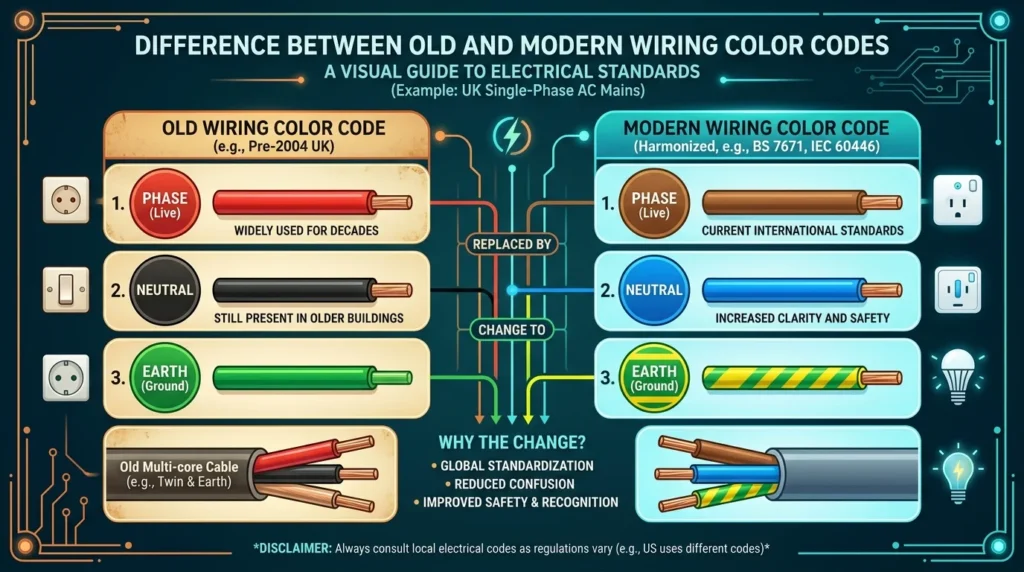
The difference between old wiring color codes and modern standards is very important during maintenance and renovation work.
| Feature | Old Wiring Colors | Modern IEC Colors |
|---|---|---|
| Live Wire | Red | Brown |
| Neutral Wire | Black | Blue |
| Earth Wire | Green | Green/Yellow |
| Safety Level | Lower standardization | Higher safety standards |
| Global Use | Limited | Internationally accepted |
Modern systems are safer and more standardized compared to older installations.
Comparison Between AC and DC Wiring Color Codes
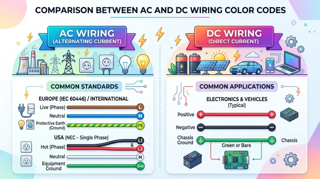
| Feature | AC Wiring | DC Wiring |
|---|---|---|
| Main Purpose | Power distribution | Battery and electronics |
| Positive Wire | Not used | Red |
| Negative Wire | Not used | Black |
| Neutral Wire | Blue or white | Sometimes unused |
| Earth Wire | Green/Yellow | Green/Yellow |
This comparison helps electricians understand different electrical systems correctly.
Selection Guide for Electrical Wiring Color Codes
Choosing and applying the correct wiring color code system is important for electrical safety, proper installation, maintenance, and compliance with applicable electrical standards. The correct approach is not simply to choose a color scheme; it is to identify the standard that applies to the particular installation and follow it consistently.
1. Follow Local Electrical Standards
Always follow the electrical regulations and wiring standards applicable to the country and type of installation.
Different regions may use different conductor identification systems. Modern installations may also follow standards that differ from older installations.
Before starting work:
- Identify the applicable electrical code.
- Check project specifications.
- Review equipment documentation.
- Follow local installation requirements.
- Use approved wiring practices.
This is especially important for commercial, industrial, and high-voltage installations.
2. Check the Type of Electrical System
Before identifying wire colors, determine what type of electrical system you are working with.
Check whether the installation uses:
- AC power
- DC power
- Single-phase supply
- Three-phase supply
- Control circuits
- Power circuits
- Grounded or ungrounded systems
For example, the color conventions used for a three-phase AC system may be different from those used for a low-voltage DC control circuit.
3. Identify the Function of Each Conductor
Do not select wire colors randomly.
First determine whether each conductor is intended to be:
- Live or line
- Neutral
- Protective earth
- Phase conductor
- Control conductor
- Signal conductor
- Positive or negative DC conductor
Once the function is known, use the conductor identification required by the applicable standard.
4. Use Proper Labels in Complex Systems
Color alone may not be enough in large electrical installations.
Complex systems should also use:
- Wire numbers
- Terminal labels
- Cable tags
- Panel labels
- Circuit identification
- Wiring diagrams
- Equipment references
Combining colors with labels makes troubleshooting and maintenance much easier.
5. Avoid Mixing Old and New Wiring Systems
Older buildings may contain wiring that follows historical color conventions, while newer sections may use modern standards.
Mixing these systems without proper identification can create confusion.
During renovation or modification:
- Identify the existing wiring system.
- Check the age and condition of the installation.
- Determine the applicable modern requirements.
- Clearly identify any transition between old and new wiring.
- Update the installation where required.
- Document the changes.
Never assume that an old wire follows modern color conventions.
6. Use High-Quality Wires and Cables
Good-quality cables should have durable insulation and clear, permanent conductor identification.
When selecting cables, consider:
- Voltage rating
- Current-carrying capacity
- Insulation type
- Temperature rating
- Environmental conditions
- Mechanical protection
- Applicable electrical standard
- Manufacturer specifications
Wire color should remain identifiable throughout the expected service life of the installation.
7. Consider the Installation Environment
The environment can affect cable insulation and conductor identification.
For example, wiring installed in:
- Outdoor areas
- High-temperature locations
- Wet environments
- Industrial plants
- Chemical facilities
- Underground systems
may require special cable construction and protection.
Tips for Beginners
Beginners should develop safe habits before working with electrical wiring.
- Never assume a conductor is safe because of its color.
- Test before touching.
- Learn the wiring standards used in your area.
- Understand the difference between live, neutral, and protective earth.
- Use properly rated test equipment.
- Follow isolation and lockout procedures where applicable.
- Never work on energized circuits unless specifically trained, authorized, and equipped for that task.
Common Problems and Solutions with Wiring Color Codes
Electrical wiring problems can occur because of incorrect installation, aging, modifications, environmental damage, or confusion between different wiring standards.
Understanding common problems helps technicians identify potential hazards more effectively.
Why Are Wire Colors Different in Old Buildings?
Older buildings may have been wired according to standards that are no longer used for new installations.
Over time, electrical systems may also have been modified or extended.
Solution
When working on an older installation:
- Identify the wiring system.
- Check available documentation.
- Inspect conductor colors carefully.
- Test the conductors.
- Follow current requirements for any new work.
- Clearly document modifications.
Do not assume that old colors have the same meaning as modern colors.
What Happens if Live and Neutral Are Reversed?
Reversing live and neutral conductors can create a dangerous condition.
Possible consequences include:
- Increased electric shock risk
- Incorrect operation of switches
- Unsafe appliance conditions
- Equipment malfunction
- Potential fire hazards in certain fault conditions
Solution
Use an appropriate wiring tester or approved test method to verify conductor connections. If reversed polarity is found, the circuit should be corrected by a qualified person according to the applicable electrical requirements.
Why Do Wire Colors Fade?
Wire insulation can lose its original appearance because of:
- Heat
- Sunlight
- Moisture
- Chemicals
- Oil
- Mechanical wear
- Long-term aging
Faded or damaged insulation can make conductor identification difficult.
Solution
Inspect wiring regularly and replace cables when their insulation is damaged or their condition is unsafe. In difficult installations, use appropriate labels and documentation to support conductor identification.
How Can Unknown Wires Be Identified?
Never guess the function of an unknown conductor based only on its color or appearance.
Suitable testing and identification methods may include:
- Digital multimeter
- Two-pole voltage tester
- Approved voltage detector
- Continuity testing when the circuit is safely isolated
- Circuit diagrams
- Cable schedules
- Panel documentation
The test instrument must be suitable for the system and correctly rated.
What If Different Color Standards Are Mixed?
Mixed wiring standards can make an installation difficult to understand and increase the risk of incorrect connections.
This can happen when:
- An old building is renovated.
- New circuits are added to an existing system.
- Equipment from another standard is installed.
- Previous modifications were poorly documented.
Solution
Use a combination of:
- Clear wire labels
- Updated wiring diagrams
- Terminal identification
- Cable markers
- Proper documentation
- Standardized wiring practices for new work
Where possible, bring modifications into compliance with the applicable current requirements.
Safety Tips for Working with Wiring Color Codes
Electrical wiring can be hazardous, particularly when circuits are energized. Proper safety procedures are more important than simply knowing wire colors.
Important Safety Practices
- Turn off and isolate the power before working whenever the procedure requires de-energization.
- Verify the absence of voltage using an appropriate and properly rated test instrument.
- Use suitable personal protective equipment for the task.
- Follow applicable electrical codes and workplace procedures.
- Use insulated tools where appropriate.
- Never touch exposed conductors directly.
- Do not rely on wire color alone.
- Use lockout/tagout procedures where required.
- Keep electrical panels and work areas organized.
- Ask a qualified electrician or supervisor when the circuit is unfamiliar or hazardous.
Importance of Protective Earth and Grounding
The protective earth or grounding system is an important part of electrical safety.
It can provide a controlled path for fault current when an insulation failure causes an exposed conductive part to become energized. This can help protective devices disconnect the faulty circuit.
A missing, damaged, or incorrectly connected protective earth can increase the risk of electric shock.
Grounding and bonding requirements vary by electrical system, so they should always be designed and verified according to the applicable standard.
Future Trends in Electrical Wiring Color Codes
Electrical installations are becoming more connected, automated, and data-driven. As a result, conductor identification is also becoming more sophisticated.
1. Smart Electrical Systems
Smart homes and buildings use connected devices, sensors, controllers, and automated equipment.
These systems may contain both traditional power wiring and low-voltage communication or control circuits.
Clear conductor identification becomes increasingly important as the number of connected devices increases.
2. Better Wire Identification
Cable manufacturers and system designers are using improved identification methods.
Modern cables and installations may include:
- Permanent printed markings
- Wire numbers
- Cable tags
- Heat-resistant identification
- Machine-readable labels
- Digital documentation
These methods can supplement traditional color identification.
3. Digital Wiring Documentation
Modern electrical projects increasingly use digital drawings, cable schedules, and asset-management systems.
Technicians can use digital documentation to identify:
- Cable routes
- Terminal numbers
- Panel connections
- Equipment locations
- Circuit functions
- Maintenance history
This can significantly improve troubleshooting in large facilities.
4. Renewable Energy Expansion
The growth of solar power, battery storage, and other renewable technologies is creating more complex AC and DC electrical systems.
These systems require clear identification of:
- DC positive conductors
- DC negative conductors
- AC phase conductors
- Neutral conductors
- Protective earth connections
- Control and communication wiring
Correct identification is especially important because some renewable energy systems can remain energized under specific conditions even when the normal utility supply is disconnected.
5. Electric Vehicle Technology
Electric vehicles and charging infrastructure contain high-power electrical circuits, batteries, control systems, and communication networks.
Clear conductor identification, labeling, and documentation are becoming increasingly important for safe installation and maintenance.
6. Automation and Intelligent Cable Management
Industrial automation is increasing the number of control, sensor, communication, and power cables used in machines and production facilities.
Modern cable-management systems can combine:
- Color identification
- Wire numbering
- Terminal markers
- Digital drawings
- Automated documentation
- Smart maintenance systems
This makes complex installations easier to maintain.
7. Increasing Safety Requirements
Electrical safety standards continue to evolve as new technologies and installation methods appear.
Engineers, technicians, and electricians must stay familiar with the requirements that apply to their specific industry and location.
Importance of Proper Training in Wiring Color Codes
Learning wiring color codes is an important part of electrical education and professional training.
Students and technicians should understand not only the colors but also why each conductor exists and how it functions in an electrical circuit.
Benefits of Proper Training
- Improves workplace safety
- Reduces installation mistakes
- Makes troubleshooting easier
- Builds professional confidence
- Improves maintenance skills
- Helps technicians understand electrical drawings
- Supports compliance with electrical standards
- Prepares workers for modern electrical technologies
- Supports professional work across different electrical environments
Practical Training Matters
The best electrical training combines theory with practical experience.
A student may memorize that a particular color commonly represents a certain conductor, but professional electrical work requires much more than memorization.
A skilled electrician or technician should know how to:
- Identify the applicable wiring standard.
- Understand the electrical circuit.
- Recognize conductor functions.
- Read wiring diagrams.
- Use appropriate testing instruments.
- Isolate electrical equipment safely.
- Verify conductor identity.
- Perform work according to the applicable code.
- Document modifications correctly.
This combination of knowledge, practical training, testing, and safety awareness helps create competent electrical professionals who can work confidently on residential, commercial, and industrial systems.
Conclusion
Wiring color codes are one of the most important parts of electrical safety and system organization. They help electricians, engineers, technicians, and beginners identify wires quickly and accurately during installation, maintenance, and troubleshooting. Proper understanding of live, neutral, earth, and phase wire colors reduces the risk of electrical accidents and improves overall system reliability.
Modern electrical systems rely heavily on standardized wiring color codes for safety, efficiency, and international compatibility. Although different countries may use different standards, the main purpose remains the same: safe and organized electrical operation. Learning wiring color codes working principle, applications, advantages and disadvantages, and troubleshooting methods is essential for anyone involved in electrical work. With the growth of smart systems, renewable energy, and industrial automation, the importance of correct wiring identification will continue increasing in the future.