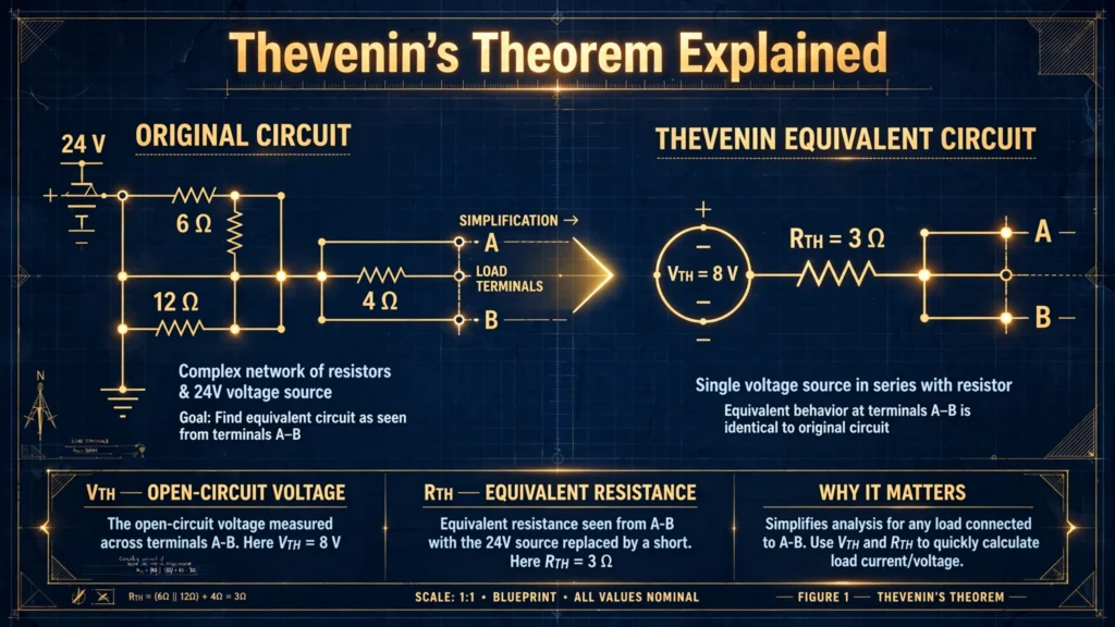

Complex circuits with multiple sources and resistors can be intimidating. Writing mesh or nodal equations for every branch works, but it is slow and error-prone — especially when you only care about what happens in one single load resistor. Thevenin’s theorem is the shortcut engineers reach for: it lets you replace an entire complicated network with one voltage source and one resistor.
In this guide, you will learn exactly what the theorem states, the step-by-step method to find the Thevenin equivalent, and two fully solved numerical examples.
What the Theorem States
Thevenin’s theorem says: any linear two-terminal network of voltage sources, current sources, and resistors can be replaced by an equivalent circuit consisting of a single voltage source (Vth) in series with a single resistor (Rth).
“Two-terminal” simply means we pick two points in the circuit — usually the terminals where the load connects — and everything on the other side of those points gets simplified. The behavior seen by the load stays exactly the same: same voltage, same current, same power.
This works because the theorem is built on linearity. If you already understand Ohm’s law and Kirchhoff’s voltage and current laws, you already have the tools needed — Thevenin’s theorem just organizes them into a repeatable recipe.
The Thevenin Equivalent Circuit
The equivalent circuit has only three elements:
- Vth (Thevenin voltage) — the open-circuit voltage measured across the two terminals with the load removed.
- Rth (Thevenin resistance) — the equivalent resistance seen from the two terminals with all independent sources turned off (voltage sources short-circuited, current sources open-circuited).
- The load (RL) — reconnected across the equivalent circuit, exactly as it was in the original.
Once you have Vth and Rth, the load current is trivial: IL = Vth / (Rth + RL). A five-resistor headache becomes a one-line calculation.
Step-by-Step Method to Find Vth and Rth
Follow these steps in order for any circuit:
Step 1 — Remove the load. Disconnect RL from terminals A and B. Keep the terminals marked.
Step 2 — Find Vth. Calculate the open-circuit voltage across A and B. With no load connected, no current flows through the open terminals, which usually simplifies the math to a basic voltage divider.
Step 3 — Find Rth. Turn off all independent sources (replace voltage sources with short circuits and current sources with open circuits), then calculate the equivalent resistance between A and B using series-parallel reduction.
Step 4 — Draw the equivalent. Sketch Vth in series with Rth, reconnect RL across the terminals, and solve for whatever the question asks — current, voltage, or power.
Solved Example 1: Finding the Load Current
Problem: A 20 V source connects in series with R1 = 5 Ω. At the far end, R2 = 10 Ω connects across the output terminals A–B, and the load RL = 10 Ω also connects across A–B. Find the current through RL using Thevenin’s theorem.
Step 1 — Remove RL. Terminals A–B are left with R2 = 10 Ω across them, fed through R1 = 5 Ω from the 20 V source.
Step 2 — Find Vth. With RL removed, R1 and R2 form a simple voltage divider:
Vth = Vs × R2 / (R1 + R2) = 20 × 10 / (5 + 10) = 200 / 15 = 13.33 V
Step 3 — Find Rth. Short the 20 V source. Looking back from A–B, R1 and R2 are in parallel:
Rth = (R1 × R2) / (R1 + R2) = (5 × 10) / 15 = 50 / 15 = 3.33 Ω
Step 4 — Reconnect and solve.
IL = Vth / (Rth + RL) = 13.33 / (3.33 + 10) = 13.33 / 13.33 = 1 A
The load current is exactly 1 ampere — a result you can verify with nodal analysis if you like.
Solved Example 2: Equivalent Circuit and Load Power
Problem: A 15 V source feeds R1 = 5 Ω in series, with R2 = 10 Ω across terminals A–B. The load is RL = 5 Ω. Find the Thevenin equivalent and the power delivered to the load.
Step 1 — Remove RL, leaving the divider R1–R2 across the source.
Step 2 — Vth:
Vth = 15 × 10 / (5 + 10) = 150 / 15 = 10 V
Step 3 — Rth (source shorted, R1 || R2):
Rth = (5 × 10) / 15 = 3.33 Ω
Step 4 — Load current and power:
IL = 10 / (3.33 + 5) = 10 / 8.33 = 1.2 A
P = IL² × RL = (1.2)² × 5 = 1.44 × 5 = 7.2 W
Bonus insight — maximum power transfer: the load receives maximum power when RL equals Rth. Here, if RL were 3.33 Ω instead of 5 Ω, the power would peak. This famous result falls straight out of the Thevenin equivalent and is a favorite exam question.
Where Thevenin’s Theorem Is Used
- Simplifying analysis — reduce part of a circuit you are not interested in, then focus on the load.
- Power systems — a whole grid as seen from one busbar is routinely replaced by its Thevenin equivalent.
- Electronics — amplifier stages and sensor interfaces are modeled as Thevenin sources to predict how they drive the next stage.
- Fault studies — short-circuit current at any point is found quickly from the Thevenin equivalent at that point.
Limitations to Keep in Mind
The theorem only applies to linear networks. Components like diodes, transistors in saturation, or saturating transformer cores break the linearity assumption. It also works with AC circuits, but then Vth and impedances become complex numbers (phasors) — the same steps apply, just with complex arithmetic.
Frequently Asked Questions
What is Thevenin’s theorem in simple words?
Any complicated circuit made of sources and resistors can be replaced — as seen from any two terminals — by a single voltage source (Vth) in series with a single resistor (Rth). The load connected to those terminals behaves exactly the same.
How do I find Rth if there are dependent sources?
Turn off independent sources as usual, but do not zero the dependent ones. Instead, apply a test voltage at the terminals, measure the current drawn, and compute Rth = Vtest / Itest.
What is the difference between Vth and the source voltage?
The source voltage is what the supply produces; Vth is the open-circuit voltage at the chosen terminals after the internal network drops some voltage. Vth equals the source voltage only if there is no series resistance between them.
Can Thevenin’s theorem be used for AC circuits?
Yes. Replace resistances with complex impedances and use phasor voltages and currents. The procedure — open-circuit voltage, deactivated-source impedance — is identical.
Why remove the load before calculating Vth?
Vth is defined as the open-circuit voltage. With the load connected, current flows and the terminal voltage drops below the open-circuit value. Removing RL isolates the network so you measure the true open-circuit voltage.
What happens if RL equals Rth?
Maximum power transfers from the network to the load. This is the maximum power transfer theorem, and it is one of the most useful direct applications of the Thevenin equivalent.
Final Thoughts
Thevenin’s theorem turns sprawling networks into a battery and a resistor — and that simplicity is its power. Practice the four steps until they feel mechanical: remove the load, find the open-circuit voltage, find the deactivated resistance, reconnect and solve. Once this feels natural, its twin — Norton’s theorem — takes only minutes to learn. For the formal statement and history, see Thévenin’s theorem on Wikipedia.