Imagine electricity traveling from a power station to your home through long transmission lines. The power plant generates thousands of kilowatts of energy, but by the time electricity reaches your house, a small portion of that energy has already been lost along the way. This loss happens because electrical conductors, wires, and equipment are not perfectly efficient.
These energy losses may seem small, but in large power systems they can result in significant wasted energy and increased operational costs. For power companies and electrical engineers, understanding how and why these losses occur is extremely important.
This is where the power loss formula becomes useful. Engineers use this formula to calculate how much electrical power is lost in transmission lines, cables, transformers, and electrical circuits.
For electrical students, technicians, and engineers, learning the power loss formula is essential for designing efficient electrical systems. It helps reduce energy waste, improve system performance, and ensure safe operation of electrical equipment.
In this article, you will learn the power loss formula, its working principle, different types of power losses, real-world power loss formula applications, and the power loss formula advantages and disadvantages. The goal is to explain this important concept clearly and practically.
2. Power Loss Formula
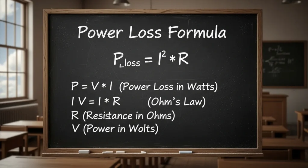
The most common formula for power loss in electrical circuits is:
P=I2R
Where:
- P = Power loss (Watts)
- I = Current (Amperes)
- R = Resistance (Ohms)
This formula shows that power loss increases with the square of the current. That means if current doubles, the power loss becomes four times greater.
Other Power Loss Formulas
Power loss can also be calculated using other electrical relationships.
Using Voltage and Current
P=VI
Where:
- P = Power (Watts)
- V = Voltage (Volts)
- I = Current (Amperes)
Using Voltage and Resistance
P=RV2
Where:
- P = Power (Watts)
- V = Voltage (Volts)
- R = Resistance (Ohms)
Example of Power Loss
Suppose:
- Current = 10 A
- Resistance = 2 Ω
Using the formula:
Power Loss = I2R
= 102×2
= 100×2
= 200 Watts
So 200 W power is lost as heat in the conductor.
Why Power Loss is Important
Power loss is important in electrical engineering because it affects:
- Transmission line efficiency
- Energy consumption
- Heating of wires
- Electrical system performance
Engineers try to reduce power loss by:
- Using high voltage transmission
- Using low resistance conductors
- Reducing current in long transmission lines
✅ Simple Rule:
Higher current → More power loss
Lower resistance → Less power loss
The power loss formula is a mathematical equation used to calculate how much electrical power is lost in a circuit due to resistance.
The most common formula used to calculate power loss is:
Power Loss (P) = I²R
Where:
- P = Power loss (Watts)
- I = Current flowing through the conductor (Amperes)
- R = Resistance of the conductor (Ohms)
This formula shows that power loss increases with the square of the current flowing through a conductor.
Simple Explanation
Whenever electric current flows through a wire, the wire’s resistance converts a small portion of electrical energy into heat. This heat represents energy that is lost from the system.
Practical Example
Suppose a transmission line carries 10 amps of current and has 2 ohms resistance.
Using the power loss formula:
P = I²R
P = (10)² × 2
P = 100 × 2
P = 200 Watts
This means 200 watts of energy are lost as heat in the conductor.
3. Power Loss Formula Working Principle
The power loss formula working principle is based on the relationship between current, resistance, and heat generation.Power Loss Formula Working Principle is an important concept in electrical engineering that explains how energy is lost in electrical systems, especially in wires and transmission lines. Whenever electric current flows through a conductor, some amount of energy is converted into heat due to the resistance of the material. This loss of energy is called power loss, and it reduces the overall efficiency of the system.
The basic formula used to calculate power loss is based on Joule’s Law of heating:
P = I^2 R
In this formula, P represents power loss in watts, I is the current flowing through the conductor in amperes, and R is the resistance of the conductor in ohms. This equation clearly shows that power loss is directly proportional to the square of the current. This means that even a small increase in current can cause a large increase in power loss.
The working principle behind this formula is simple. When current flows through a conductor, electrons collide with atoms inside the material. These collisions produce heat energy, which is lost to the surroundings. This heat generation is unavoidable in practical systems, but it can be minimized by proper design. For example, using conductors with low resistance or reducing the current can help decrease power loss.
Another important formula related to power loss in terms of voltage is:
[
P = \frac{V^2}{R}
]
Here, V represents voltage. This form of the equation is useful in certain circuit calculations. In power transmission systems, engineers often increase the voltage and reduce the current to minimize losses, because lower current results in lower ( I^2R ) losses.
In practical applications, power loss occurs in transmission lines, transformers, motors, and electrical appliances. For example, long-distance power lines experience significant losses due to resistance, which is why high-voltage transmission is used. Similarly, in household wiring, poor quality cables or loose connections can increase resistance and cause more power loss.
Understanding the working principle of the power loss formula helps engineers design efficient electrical systems. By reducing resistance, controlling current, and using proper materials, power losses can be minimized, leading to better performance, energy savings, and improved system reliability.
When electric current flows through a conductor, electrons move through the material. As these electrons move, they collide with atoms inside the conductor.
These collisions create heat energy, which results in power loss.
Power Loss in Electrical Conductors: Step-by-Step Mechanism Explained
Power loss in an electrical conductor mainly occurs due to the conversion of electrical energy into heat energy when current flows through a material that has resistance. This process is gradual and can be clearly understood through the following steps:
Step-by-Step Process of Power Loss
- Electric Current Flow
When electrical current flows through a conductor, electrons start moving from one atom to another under the influence of applied voltage. - Presence of Resistance
Every conductor offers some resistance to the flow of electrons, which restricts their smooth movement. - Electron Collisions
As electrons move, they continuously collide with atoms and ions inside the conductor material. - Heat Generation
These collisions transfer energy to the atoms, causing them to vibrate more and produce heat. - Energy Dissipation (Power Loss)
The electrical energy is converted into heat energy, and this lost energy is known as power loss (I²R loss) in the conductor.
Simple Flow Diagram of Power Loss
Electric Current
      ↓
Resistance in Conductor
      ↓
Electron Collisions
      ↓
Heat Generation
      ↓
Power Loss (I²R Loss)
Key Idea
In simple terms, the higher the current and resistance, the greater the power loss, because more electrical energy is converted into heat inside the conductor.
If you want, I can also add the formula derivation (P = I²R, P = V²/R) with a clear diagram for exams and notes.
Simple Analogy
Imagine water flowing through a narrow pipe. Friction between water and the pipe walls reduces the water pressure. Similarly, resistance in electrical conductors reduces electrical energy.
4. Types / Classification of Power Loss
Power losses in electrical systems can be classified into different categories depending on how and where the energy is wasted. These losses reduce the efficiency of electrical equipment and increase operating costs. Understanding the various types of power loss helps engineers identify problems and apply suitable methods to minimize energy wastage. Proper analysis of these losses is essential for designing efficient and reliable electrical systems.
Resistive Loss (I²R Loss)
Resistive loss, also known as copper loss, is the most common form of power loss in electrical circuits. It occurs because conductors have resistance that opposes the flow of electric current. As current passes through wires and transmission lines, part of the electrical energy is converted into heat. The amount of resistive loss is calculated using the formula P = I²R, showing that losses increase rapidly as current increases.
Characteristics
- Occurs in wires and transmission lines.
- Directly related to current flow.
- Produces heat in conductors.
- Calculated using the power loss formula.
Core Loss
Core loss occurs in transformers, generators, and other electrical machines that use magnetic cores. These losses arise due to repeated magnetization and demagnetization of the iron core during AC operation. Unlike copper losses, core losses exist even when the equipment is operating without load. They generate heat and reduce the overall efficiency of electrical machines.
Types of Core Loss
Hysteresis Loss
Hysteresis loss occurs because magnetic materials resist changes in magnetization. Energy is consumed during each cycle as the magnetic domains continuously realign themselves. This loss depends on the type of core material and operating frequency.
Eddy Current Loss
Eddy current loss is caused by small circulating currents induced within the iron core. These currents generate unwanted heat and waste energy. Laminated cores are commonly used to reduce this type of loss.
Dielectric Loss
Dielectric loss occurs in insulating materials used in cables, capacitors, transformers, and high-voltage equipment. Although insulators are designed to prevent current flow, a small amount of energy is dissipated as heat when subjected to alternating electric fields. Dielectric losses become more significant at higher voltages and frequencies. Proper insulation selection helps minimize these losses.
Mechanical Loss
Mechanical losses occur in rotating electrical machines such as motors and generators. These losses are associated with the movement of mechanical parts rather than electrical resistance. Mechanical losses reduce machine efficiency and contribute to heating and wear over time. Regular maintenance is essential to keep these losses under control.
Types of Mechanical Loss
Friction Loss
Friction loss occurs due to contact between moving parts such as bearings, brushes, and shafts. Poor lubrication or worn components can increase friction and reduce machine performance.
Windage Loss
Windage loss results from air resistance encountered by rotating components. High-speed machines experience greater windage losses because of increased turbulence and drag.
5. Main Components Affecting Power Loss
Several factors influence the amount of power loss in electrical systems. These factors determine how efficiently electricity can be transmitted and utilized. Understanding them enables engineers to improve performance, reduce energy waste, and enhance system reliability. Proper component selection plays a vital role in minimizing losses.
Current (I)
Current has the greatest impact on resistive power loss because the loss varies with the square of current. Even a small increase in current can significantly increase heat generation and energy wastage. Therefore, engineers often reduce current levels by using higher transmission voltages. Controlling current helps improve efficiency and extend equipment life.
Resistance (R)
Resistance represents the opposition offered by a conductor to the flow of current. It depends on the conductor material, length, cross-sectional area, and temperature. Higher resistance leads to greater energy losses and voltage drops. Selecting conductors with low resistance is essential for efficient electrical systems.
Conductor Length
Longer conductors have higher resistance because electrons must travel through a greater distance. As conductor length increases, power losses and voltage drops also increase. Engineers attempt to optimize system layouts to reduce unnecessary cable lengths. This helps improve overall efficiency and lower operating costs.
Conductor Material
The material used for conductors greatly influences power loss. Copper and aluminum are commonly used because they offer low resistance and good conductivity. Copper provides excellent performance, while aluminum is lighter and more economical for transmission applications. Choosing the right material ensures an effective balance between efficiency and cost.
Temperature
Temperature affects the resistance of conductors directly. As temperature rises, conductor resistance increases, causing greater power losses. Excessive heating can also damage insulation and shorten equipment lifespan. Proper cooling and ventilation systems help maintain safe operating temperatures and improve efficiency.
6. Advantages of Using the Power Loss Formula
The power loss formula is a valuable tool in electrical engineering because it allows engineers to estimate energy losses accurately. It supports the design of efficient electrical systems and helps identify areas where improvements can be made. By understanding how losses occur, organizations can reduce waste and lower costs. The formula is widely used in both academic studies and practical applications.
Advantages
- Helps calculate energy loss accurately.
- Assists in designing efficient systems.
- Improves energy management.
- Reduces electricity waste.
- Optimizes transmission line design.
- Useful for troubleshooting circuits.
7. Disadvantages / Limitations
Although the power loss formula is highly useful, it has certain limitations. It mainly focuses on resistive losses and assumes that resistance remains constant. In reality, electrical systems involve many additional factors that influence efficiency. Engineers often use advanced analytical methods alongside this formula for more accurate results.
Limitations
- Mainly applies to resistive losses.
- Assumes constant resistance.
- Does not directly include reactive power effects.
- Real systems involve additional losses.
- Advanced systems require detailed analysis.
8. Power Loss Formula Applications
The power loss formula has numerous practical applications in electrical engineering. It is used to estimate energy losses, improve system efficiency, and optimize equipment design. Engineers rely on these calculations to ensure safe and economical operation. Its applications extend across power generation, transmission, distribution, and renewable energy systems.
Transmission Lines
Power utilities use the formula to estimate losses during electricity transmission over long distances. These calculations help determine conductor sizes and transmission voltages that minimize energy waste. Reducing transmission losses improves the efficiency of the power grid and lowers operating costs.
Electrical Wiring
Electrical engineers use power loss calculations when designing residential, commercial, and industrial wiring systems. The formula helps select appropriate conductor sizes and ensures that voltage drops remain within acceptable limits. This results in safer and more efficient installations.
Transformer Design
Transformer designers apply the formula to evaluate winding losses and improve transformer performance. Understanding these losses allows manufacturers to enhance efficiency and reduce heat generation. Efficient transformer design contributes to lower energy consumption and increased reliability.
Motor Systems
Power loss calculations are important for improving the efficiency of electric motors used in industries. Engineers use them to identify overload conditions, select suitable motor ratings, and optimize operating performance. This reduces operating costs and increases equipment lifespan.
Renewable Energy Systems
Wind farms and solar power plants use power loss calculations to optimize power delivery from generation sources to consumers. These calculations assist in selecting cables, designing layouts, and maximizing energy output. Efficient renewable energy systems provide greater sustainability and economic benefits.
9. Comparison Section
Difference Between Power Loss Formula and Power Formula
| Feature | Power Loss Formula | Power Formula |
|---|---|---|
| Purpose | Calculates energy loss | Calculates electrical power |
| Equation | P = I²R | P = VI |
| Application | Transmission lines and conductors | General electrical systems |
| Output | Heat loss | Useful electrical power |
Understanding the difference between power formula and power loss formula is important for electrical calculations.
10. Selection Guide
When designing electrical systems, engineers must minimize power loss.10. Methods to Reduce Power Loss
Reducing power loss is one of the main goals of electrical engineers because it improves system efficiency, lowers operating costs, and minimizes energy wastage. Excessive losses not only waste electricity but also generate heat that can damage equipment and reduce its lifespan. By applying suitable techniques, power systems can deliver electricity more effectively and economically.
Use Low-Resistance Conductors
One of the simplest ways to reduce power loss is by using conductors with low electrical resistance. Materials such as copper and aluminum are widely used because they allow electric current to flow more easily. Lower resistance means less energy is converted into heat as current passes through the conductor. Copper is especially preferred in many electrical installations because of its excellent conductivity and durability, while aluminum is often used in transmission lines due to its lighter weight and lower cost.
Benefits
- Reduces I²R losses.
- Improves system efficiency.
- Minimizes heat generation.
- Increases equipment reliability.
- Lowers long-term energy costs.
Increase Voltage
Increasing transmission voltage is one of the most effective methods of reducing power loss in electrical systems. Since power loss depends on the square of current, transmitting electricity at higher voltages allows the same amount of power to be delivered with much lower current. Lower current significantly decreases resistive losses in transmission lines.
This is why electricity generated at power stations is stepped up to very high voltages before being transmitted over long distances and then stepped down near consumers for safe use.
Benefits
- Reduces current flow.
- Minimizes transmission losses.
- Improves transmission efficiency.
- Allows long-distance power delivery.
- Reduces conductor heating.
Reduce Transmission Distance
The resistance of a conductor increases with its length. Therefore, longer transmission lines result in greater power losses. Reducing the distance electricity travels can significantly improve efficiency and reduce wasted energy.
Although long-distance transmission is sometimes unavoidable, engineers optimize network layouts and strategically place substations to minimize unnecessary line lengths.
Benefits
- Reduces conductor resistance.
- Minimizes voltage drops.
- Improves energy efficiency.
- Lowers operating costs.
- Enhances power quality.
Use Proper Conductor Size
Selecting conductors with the correct cross-sectional area is essential for efficient power transmission. Larger conductors have lower resistance because they provide a greater path for electron flow. As resistance decreases, power losses are reduced.
While larger conductors may cost more initially, they often result in substantial savings over time due to improved efficiency and lower energy losses.
Benefits
- Decreases resistance.
- Reduces heat generation.
- Improves system performance.
- Enhances safety.
- Extends equipment lifespan.
These techniques collectively help improve the efficiency of electrical systems and ensure that electricity reaches consumers with minimal losses.
11. Common Problems & Solutions
Understanding common issues related to power loss helps engineers, technicians, and students diagnose problems and implement effective solutions. Many of these problems occur regularly in electrical systems and can often be prevented through proper design and maintenance.
Q1: Why Does Power Loss Increase with Current?
Explanation
Power loss caused by resistance follows the formula:
[
P = I^2R
]
This means that current has a squared effect on power loss. Even a small increase in current can lead to a much larger increase in energy loss. For example, if the current doubles, the power loss becomes four times greater.
Solution
- Reduce unnecessary current flow.
- Increase transmission voltage.
- Balance electrical loads properly.
- Avoid overloading circuits.
- Use appropriately sized conductors.
Controlling current levels is one of the most effective ways to improve efficiency.
Q2: How Can Power Loss Be Reduced?
Explanation
Power loss cannot be completely eliminated, but it can be minimized through proper engineering practices. Reducing losses improves efficiency, decreases electricity costs, and extends equipment life.
Solution
- Use high-voltage transmission systems.
- Install thicker conductors where required.
- Choose low-resistance materials such as copper.
- Reduce transmission distances when possible.
- Perform regular maintenance.
- Ensure proper cooling and ventilation.
Applying these methods significantly improves system performance.
Q3: Why Do Transmission Lines Operate at High Voltage?
Explanation
Transmission lines carry large amounts of electrical power over long distances. If low voltage were used, very high currents would be required to deliver the same power. High current would produce excessive I²R losses.
By increasing voltage, the required current decreases, reducing energy losses and improving efficiency.
Solution
Power systems use transformers to:
- Step up voltage at generating stations.
- Lower current during transmission.
- Minimize resistive losses.
- Improve transmission economy.
- Step down voltage near consumers for safe use.
This approach is a fundamental principle of modern power distribution systems.
Q4: Why Do Wires Get Hot?
Explanation
When electric current flows through a conductor, resistance opposes the movement of electrons. Part of the electrical energy is converted into thermal energy, causing the wire to heat up. Excessive heating can damage insulation and create safety hazards.
Solution
- Use conductors with adequate current ratings.
- Avoid circuit overloading.
- Tighten loose electrical connections.
- Improve ventilation around equipment.
- Replace damaged or undersized wires.
- Conduct regular inspections and maintenance.
Managing heat effectively helps maintain safety, reliability, and system efficiency.
Reducing power loss is essential for building efficient and reliable electrical systems. Techniques such as using low-resistance conductors, increasing transmission voltage, reducing transmission distances, and selecting proper conductor sizes help minimize wasted energy and improve overall performance. At the same time, understanding common problems such as excessive current, wire heating, and transmission losses enables engineers to apply practical solutions before major failures occur.
By combining good design practices with regular maintenance and proper troubleshooting, electrical systems can operate more safely, economically, and efficiently. These strategies not only reduce electricity waste but also support sustainable energy use and long-term operational success.
12. Future Trends in Power Loss Reduction
Electrical engineering is rapidly evolving to minimize power losses in transmission, distribution, and utilization systems. With increasing global energy demand, modern technologies are being developed to improve efficiency, reduce wastage, and enhance overall system performance.
Smart Power Grids
Smart grids use digital communication, sensors, and real-time monitoring systems to optimize electricity flow. They help detect losses, manage load distribution efficiently, and reduce unnecessary energy waste in the system. By automatically adjusting power supply based on demand, smart grids significantly improve overall efficiency.
High Voltage Direct Current (HVDC) Transmission
HVDC systems are widely used for long-distance power transmission because they reduce energy losses compared to AC systems. By transmitting electricity at very high voltage and low current, HVDC minimizes I²R losses, making it more efficient for bulk power transfer over long distances and underwater cables.
Superconductors
Superconducting materials have almost zero electrical resistance when cooled below a certain temperature. This allows electric current to flow without energy loss. Although still under development for large-scale applications, superconductors have the potential to revolutionize power systems by eliminating resistive losses almost completely.
Advanced Conductor Materials
Researchers are developing new conductor materials such as carbon-based conductors, aluminum alloys, and nano-engineered materials that offer lower resistance and improved conductivity. These advanced materials help reduce heat generation and improve energy efficiency in electrical systems.
Energy-Efficient Power Electronics
Modern power electronic devices such as IGBTs, MOSFETs, and silicon carbide (SiC) semiconductors improve switching efficiency and reduce conversion losses. These technologies are widely used in renewable energy systems, electric vehicles, and industrial drives.
Integration of Renewable Energy Systems
The use of solar, wind, and hybrid energy systems reduces dependence on long transmission networks, thereby lowering overall power loss. Decentralized power generation also improves system reliability and efficiency.
Artificial Intelligence and Predictive Analytics
AI-based systems analyze load patterns, detect faults, and optimize energy distribution in real time. Predictive maintenance reduces equipment failures and minimizes energy losses caused by system inefficiencies.
These emerging technologies are transforming the future of electrical power systems. By combining smart monitoring, advanced materials, and efficient transmission methods, engineers aim to significantly reduce global power losses and create more sustainable and energy-efficient electrical networks.
13. Conclusion
The power loss formula is one of the most important concepts in electrical engineering. It helps engineers calculate the amount of electrical energy lost due to resistance in conductors and electrical systems.
In this article, we explored the power loss formula working principle, different types of power losses, practical power loss formula applications, and the power loss formula advantages and disadvantages. We also discussed ways to reduce energy losses and improve electrical system efficiency.
For electrical students, engineers, and technicians, understanding power loss calculations is essential for designing efficient power transmission systems. As electrical networks continue to expand worldwide, minimizing energy loss will remain a key challenge for engineers.
Learning and applying the power loss formula is an important step toward building more efficient and sustainable electrical systems.