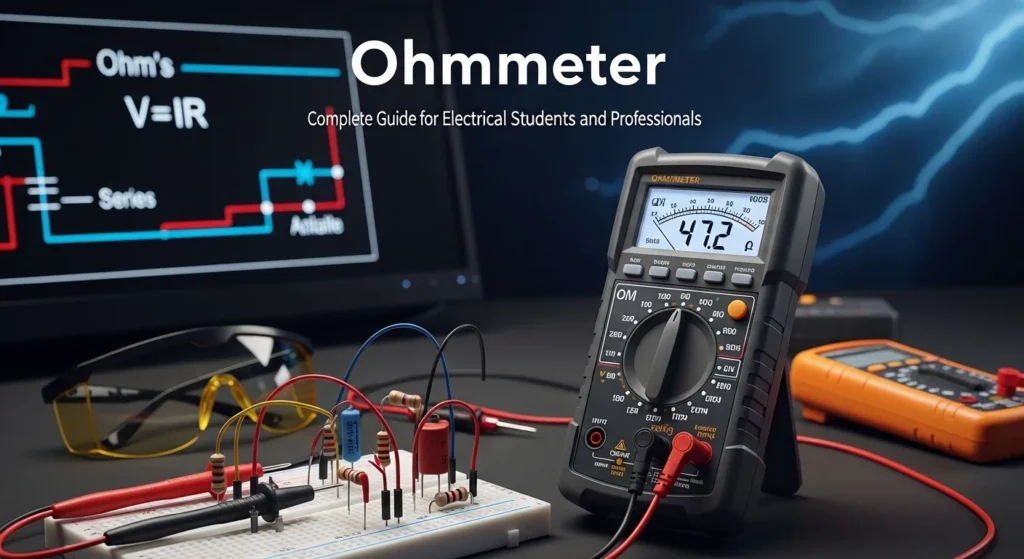

Imagine you are repairing a faulty electric fan at home. The power supply is fine, but the fan is not working. You suspect a broken wire or a damaged coil. How do you confirm it? This is where an ohmmeter becomes your best tool.
An ohmmeter helps you quickly check whether a circuit is open, closed, or has the correct resistance. It saves time, prevents guesswork, and ensures safety while troubleshooting electrical systems.
Understanding the ohmmeter working principle is essential for students, technicians, and engineers. It is one of the basic instruments used in electrical testing and maintenance. Whether you are working on small household circuits or large industrial systems, knowing how to use an ohmmeter is a fundamental skill.
In this article, you will learn everything about an ohmmeter—its definition, working, types, components, applications, advantages, and limitations. By the end, you will confidently understand how to select and use the right ohmmeter in real-world situations.
2. What is Ohmmeter?
An ohmmeter is an electrical measuring instrument used to measure the resistance of a circuit, component, or conductor.
In simple terms, it tells you how much a material resists the flow of electric current.
Understanding Resistance Measurement with an Ohmmeter
Resistance is the opposition that a material or component offers to the flow of electric current, and it is measured in ohms (Ω). The higher the resistance value, the more difficult it is for electrical current to pass through the circuit. An ohmmeter is a specialized instrument used to measure this resistance. It works by applying a small internal voltage across the component being tested and then measuring the resulting current flow. Using this information, the meter calculates and displays the resistance value. This measurement helps electricians, technicians, and engineers determine whether electrical components and circuits are functioning correctly.
Practical Example of Resistance Testing
A common use of an ohmmeter is checking the condition of electrical wires and conductors. When an ohmmeter is connected to a wire, a low resistance reading indicates that the wire is continuous and in good condition, allowing current to flow easily. On the other hand, an extremely high or infinite resistance reading usually indicates a broken wire, an open circuit, or a damaged connection that prevents current flow. Because of its ability to quickly identify faults such as broken wires, damaged components, and poor connections, an ohmmeter is considered one of the most important tools for electrical troubleshooting and maintenance.
3. Working Principle of an Ohmmeter: How Resistance is Measured
The working principle of an ohmmeter is based on Ohm’s Law, which explains the relationship between voltage, current, and resistance in an electrical circuit. An ohmmeter is designed to measure the resistance of a component by using its own internal battery to supply a small voltage. When the meter probes are connected across a resistor or electrical component, this voltage causes a small current to flow through the circuit. The meter then measures the amount of current flowing and uses Ohm’s Law to calculate the resistance value. The calculated resistance is displayed on the meter screen, allowing the user to determine the condition of the component being tested.
How an Ohmmeter Works Step by Step
The measurement process begins when the ohmmeter’s internal battery supplies a low voltage to the test circuit. This voltage drives a small current through the unknown resistance. The meter continuously monitors the current flow and compares it with the applied voltage. Based on these values, the instrument automatically calculates the resistance and displays the result in ohms (Ω). Components with low resistance allow more current to flow, while components with high resistance restrict the current flow.
Simple Analogy for Understanding
A simple way to understand an ohmmeter is to imagine water flowing through a pipe. A wide pipe allows water to flow easily, which is similar to a circuit with low resistance. A narrow pipe restricts water flow, just as high resistance restricts electrical current. The ohmmeter essentially checks how easily current can move through a component, helping determine whether the electrical path is open, damaged, or functioning normally.
Important Safety Considerations
For accurate and safe measurements, an ohmmeter should always be used on a de-energized circuit. Any external voltage present in the circuit can interfere with the reading and may damage the meter. Therefore, power must be disconnected before testing. Modern ohmmeters also include internal calibration systems that help maintain measurement accuracy and provide reliable resistance readings during troubleshooting and maintenance tasks.
4. Types / Classification of Ohmmeter
Ohmmeters are classified based on their design and application.
What is a Series Ohmmeter?
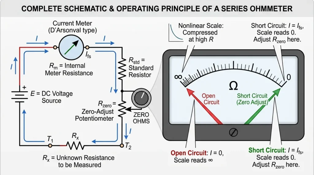
A series ohmmeter is a type of ohmmeter in which the unknown resistance is connected in series with the internal battery and measuring meter.
It is commonly used to measure medium to high resistance values and is one of the simplest forms of resistance-measuring instruments.
Series Ohmmeter Working Principle
The series ohmmeter working principle is based on Ohm’s Law:
genui{“math_block_widget_always_prefetch_v2”:{“content”:”R = \frac{V}{I}”}}
In this instrument, the current flowing through the circuit changes depending on the resistance being measured.
Step-by-Step Working
- The internal battery supplies a fixed voltage.
- The unknown resistance (Rx) is connected in series with the meter.
- Current flows through the circuit.
- The meter measures the current and converts it into resistance.
Key Concept
- Low resistance → High current → Needle moves right
- High resistance → Low current → Needle moves left
- Infinite resistance → No current → Needle at zero
Simple Understanding
Think of a road:
- Wide road (low resistance) → more cars (current) can pass
- Narrow road (high resistance) → fewer cars pass
The series ohmmeter measures how easily current flows through the “road.”
Circuit Diagram Explanation
A basic series ohmmeter includes:
- Battery (DC source)
- Galvanometer (meter movement)
- Series resistor
- Unknown resistance (Rx)
- Test leads
All components are connected in a single loop (series circuit).
Scale Characteristics
The scale of a series ohmmeter is non-linear (not uniform).
- Zero resistance is on the right side
- Infinite resistance is on the left side
This is opposite to voltmeters and ammeters.
Advantages of Series Ohmmeter
- Simple and low-cost design
- Easy to use for beginners
- Suitable for general resistance measurement
- Portable and widely available
Disadvantages of Series Ohmmeter
- Not suitable for very low resistance measurement
- Accuracy depends on battery condition
- Scale is non-linear and harder to read
- Requires zero adjustment before use
Applications of Series Ohmmeter
The series ohmmeter applications include:
- Checking continuity of wires
- Testing resistors
- Detecting open circuits
- Basic electrical troubleshooting
- Educational and training purposes
Important Note (Practical Tip)
Before using a series ohmmeter:
- Short the probes together
- Adjust the zero knob to set the meter to zero resistance
- This ensures accurate readings
A series ohmmeter is a simple and effective tool for measuring resistance by placing the unknown resistor in series with the circuit. It works on the principle of current variation and is widely used for basic electrical testing and troubleshooting.
If you are a beginner, mastering this type of ohmmeter will build a strong foundation in electrical measurements.
In this type:
- The unknown resistance is connected in series with the meter.
- Used for measuring medium resistance values.
Features:
- Simple design
- Common in analog meters
What is a Shunt Ohmmeter?
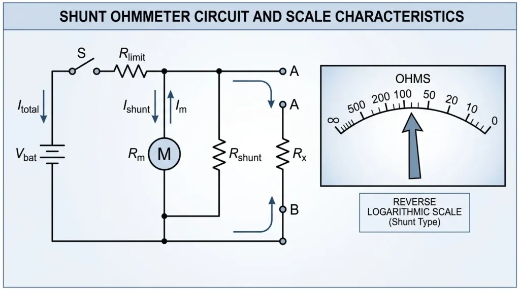
A shunt ohmmeter is a type of ohmmeter in which the unknown resistance is connected in parallel (shunt) with the measuring instrument.
It is specially designed to measure very low resistance values, where a series ohmmeter would not give accurate results.
Shunt Ohmmeter Working Principle
The shunt ohmmeter working principle is also based on Ohm’s Law, but it uses current division instead of total current variation:
genui{“math_block_widget_always_prefetch_v2”:{“content”:”I = \frac{V}{R}”}}
In this setup, current splits between the meter and the unknown resistance.
Step-by-Step Working
- The internal battery provides a constant voltage.
- The unknown resistance (Rx) is connected in parallel with the meter.
- Current divides between:
- The meter branch
- The unknown resistance branch
- The meter measures the portion of current flowing through it.
- Based on this current, resistance is calculated.
Key Concept
- Low resistance (Rx ↓) → More current bypasses meter → Needle moves left
- High resistance (Rx ↑) → Less current bypasses meter → Needle moves right
- Infinite resistance → All current flows through meter → Maximum deflection
Simple Understanding
Imagine a water system:
- Two parallel pipes (paths)
- Water prefers the easier path (low resistance)
If one pipe becomes very easy (low resistance), most water flows through it, reducing flow in the other pipe (meter). That is how a shunt ohmmeter detects resistance.
Circuit Diagram Explanation
A typical shunt ohmmeter includes:
- Battery (DC source)
- Galvanometer (meter movement)
- Shunt resistor
- Unknown resistance (Rx) connected in parallel
- Test leads
The key feature is the parallel connection of the unknown resistance.
Scale Characteristics
The scale of a shunt ohmmeter is also non-linear, but opposite to a series ohmmeter:
- Zero resistance → Left side of scale
- Infinite resistance → Right side of scale
Advantages of Shunt Ohmmeter
- Best for measuring low resistance values
- More accurate than series type for small resistances
- Useful in industrial and precision testing
- Helps in checking joints and connections
Disadvantages of Shunt Ohmmeter
- Not suitable for high resistance measurement
- Circuit design is slightly more complex
- Requires proper calibration
- Affected by battery condition
Applications of Shunt Ohmmeter
The shunt ohmmeter applications include:
- Measuring contact resistance
- Testing cable joints and connectors
- Checking busbar connections
- Industrial maintenance work
- Quality testing of electrical connections
Series vs Shunt Ohmmeter (Quick Difference)
| Feature | Series Ohmmeter | Shunt Ohmmeter |
|---|---|---|
| Connection | Series | Parallel (Shunt) |
| Best for | Medium/high resistance | Low resistance |
| Scale | Zero on right | Zero on left |
| Accuracy (low R) | Low | High |
This clearly explains the difference between series and shunt ohmmeter.
Practical Tip
Before using a shunt ohmmeter:
- Ensure the circuit is disconnected from power
- Check battery condition
- Calibrate properly for accurate readings
A shunt ohmmeter is an important instrument for measuring low resistance values with better accuracy. It works on the principle of current division and is widely used in industrial testing and electrical maintenance.
For students and technicians, understanding both series and shunt types is essential for mastering resistance measurement techniques.
- The unknown resistance is connected in parallel.
- Used for measuring low resistance values.
Features:
- Accurate for low resistance
- Used in specialized applications
What is a Multi-Range Ohmmeter?
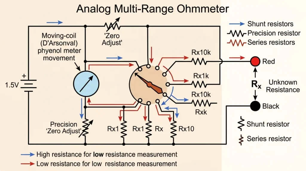
A multi-range ohmmeter is an advanced type of ohmmeter that can measure resistance across multiple ranges using a selector switch.
Unlike basic ohmmeters that measure only a fixed range, this instrument allows you to measure low, medium, and high resistance values using a single device.
It is commonly found in analog multimeters and is widely used by electricians, technicians, and engineers.
Multi-Range Ohmmeter Working Principle
The multi-range ohmmeter working principle is based on Ohm’s Law, where resistance is calculated by controlling current flow:
genui{“math_block_widget_always_prefetch_v2”:{“content”:”R = \frac{V}{I}”}}
The key idea is that the meter changes its internal resistance to adjust the measurement range.
Step-by-Step Working
- The internal battery provides a constant voltage.
- The selector switch changes internal resistors.
- This adjusts the current flowing through the circuit.
- The unknown resistance (Rx) is connected.
- The meter displays resistance based on current flow.
Key Concept
- Different ranges (e.g., ×1, ×10, ×100, ×1k) are selected manually.
- Each range multiplies the reading on the scale.
- Proper range selection ensures accurate and readable results.
Simple Understanding
Think of measuring distance:
- A ruler is good for small lengths
- A measuring tape is better for long distances
Similarly, a multi-range ohmmeter lets you choose the “right scale” for resistance.
Types of Multi-Range Ohmmeter
Analog Multi-Range Ohmmeter: Construction, Working, and Applications
- Uses a needle (pointer)
- Requires manual reading
- Common in basic multimeters
An Analog Multi-Range Ohmmeter is a type of resistance-measuring instrument that uses a moving pointer and scale to display resistance values. Unlike a single-range ohmmeter, it can measure a wide range of resistance values by allowing the user to select different measurement ranges using a range selector switch. This versatility makes it useful for testing various electrical and electronic components, from low-resistance conductors to high-resistance circuits.
Construction of an Analog Multi-Range Ohmmeter
An analog multi-range ohmmeter consists of several important components, including an internal battery, a moving-coil meter movement, range selector switch, internal resistors, and test leads. The internal battery provides the voltage needed for resistance measurement, while the meter movement displays the measured value through a pointer that moves across a calibrated resistance scale. The range selector switch changes the measurement range by connecting different internal resistors into the circuit, enabling the instrument to measure both low and high resistance values accurately.
Working Principle
The working principle of an analog multi-range ohmmeter is based on Ohm’s Law. When the test leads are connected across an unknown resistor, the internal battery sends a small current through the component. The amount of current flowing depends on the resistance being measured. The meter movement responds to this current and moves the pointer accordingly. A low resistance allows more current to flow, causing a larger pointer deflection, while a high resistance restricts current flow and produces a smaller deflection. By selecting the appropriate range, the user can obtain accurate readings over a broad resistance spectrum.
Advantages of Analog Multi-Range Ohmmeter
One of the main advantages of an analog multi-range ohmmeter is its ability to measure a wide variety of resistance values using a single instrument. It is simple to operate, cost-effective, and useful for observing gradual changes in resistance because the pointer movement provides a visual indication of variations. It also does not require complex electronic circuitry, making it durable and reliable for basic electrical testing.
Applications
Analog multi-range ohmmeters are commonly used in electrical maintenance, electronic troubleshooting, educational laboratories, and repair workshops. They are used to check resistor values, test wire continuity, identify open circuits, and locate faults in electrical systems. Although digital meters are more common today, analog multi-range ohmmeters remain valuable for learning basic measurement principles and for applications where pointer movement helps observe changing resistance values.
An analog multi-range ohmmeter is a practical resistance-measuring instrument that combines multiple measurement ranges with a simple analog display. Its ability to measure different resistance levels, along with its straightforward operation and reliability, makes it an important tool for students, technicians, and electricians involved in electrical testing and troubleshooting.
Digital Multi-Range Ohmmeter: Features, Working Principle, and Applications
- Displays readings in numbers
- More accurate and easy to use
- Often includes auto-ranging
A Digital Multi-Range Ohmmeter is an advanced resistance-measuring instrument that displays resistance values on a digital screen instead of using a pointer and scale. It is designed to measure a wide range of resistance values with high accuracy and ease of use. Most modern digital ohmmeters are integrated into digital multimeters (DMMs), making them one of the most commonly used tools for electrical and electronic testing. Their clear digital display eliminates reading errors and allows users to obtain precise measurements quickly.
Construction of a Digital Multi-Range Ohmmeter
A digital multi-range ohmmeter consists of several key components, including an internal battery, electronic measuring circuit, analog-to-digital converter (ADC), microprocessor, digital display, range selector, and test leads. The internal battery supplies the necessary power for resistance measurement, while the electronic circuit controls the flow of current through the component being tested. The analog-to-digital converter processes the measured signals and converts them into digital values, which are then displayed on the screen for easy reading.
Working Principle
The working principle of a digital multi-range ohmmeter is based on Ohm’s Law. When the test leads are connected across an unknown resistor, the meter applies a small known voltage or current to the component. The instrument then measures the resulting current or voltage and uses an internal electronic circuit to calculate the resistance value. The calculated resistance is instantly converted into a digital reading and displayed on the LCD screen. Many digital ohmmeters also feature auto-ranging, which automatically selects the most suitable measurement range, making operation simpler and more accurate.
Advantages of Digital Multi-Range Ohmmeter
Digital multi-range ohmmeters offer several advantages over analog models. They provide higher accuracy, improved readability, faster measurements, and reduced human reading errors. The digital display allows users to view exact resistance values without interpreting a scale. Many models also include additional features such as auto-ranging, data hold functions, continuity testing, and overload protection, making them highly versatile for professional use.
Applications
Digital multi-range ohmmeters are widely used in electrical maintenance, electronics repair, industrial troubleshooting, laboratory testing, and educational environments. They are commonly used to measure resistor values, check circuit continuity, test wiring systems, identify faulty components, and diagnose electrical problems. Their accuracy and convenience make them essential tools for electricians, engineers, technicians, and students.
A digital multi-range ohmmeter is a modern and highly accurate instrument for measuring electrical resistance across a wide range of values. Its digital display, automatic range selection, and advanced electronic circuitry make it more convenient and reliable than traditional analog ohmmeters. As a result, it has become one of the most widely used instruments for electrical testing, troubleshooting, and maintenance in both professional and educational settings.
Main Components of Multi-Range Ohmmeter
4. Main Components of an Ohmmeter and Their Functions
An ohmmeter consists of several important components that work together to measure electrical resistance accurately. Each part plays a specific role in the measurement process, ensuring reliable and precise readings. Understanding these components helps users learn how an ohmmeter operates and why it is an essential tool for electrical testing and troubleshooting.
1. Internal Battery
The internal battery is the power source of the ohmmeter. It provides the small voltage required to send current through the component or circuit being tested. Since resistance measurement is based on the relationship between voltage and current, the battery is a crucial part of the instrument. Without the internal battery, the ohmmeter would not be able to perform resistance measurements.
2. Meter Movement or Digital Display
The meter movement in analog ohmmeters or the digital display in modern ohmmeters shows the measured resistance value. In analog instruments, a pointer moves across a calibrated scale, while digital meters display the resistance directly on an LCD screen. This component allows users to easily read and interpret measurement results.
3. Range Selector Switch
The range selector switch allows the user to choose the appropriate resistance measurement range. Different electrical components have different resistance values, so selecting the correct range improves measurement accuracy and prevents incorrect readings. Modern digital ohmmeters may automatically select the range, while manual models require the user to choose it.
4. Internal Resistors
Internal resistors help control and regulate the current flowing through the meter during measurement. They adjust the current according to the selected range and protect the instrument from excessive current. These resistors play an important role in maintaining accuracy and ensuring proper operation across different resistance ranges.
5. Test Leads
Test leads are the wires connected to the ohmmeter that make contact with the component being tested. They provide a path for current to flow between the meter and the circuit. Typically, one lead is black (common) and the other is red (positive). Properly connected test leads ensure accurate resistance measurements and reliable testing results.
The internal battery, display system, range selector switch, internal resistors, and test leads are the primary components of an ohmmeter. Together, these parts enable the instrument to measure resistance accurately and efficiently, making it an indispensable tool for electricians, technicians, engineers, and students.
Range Settings Explained
Common range settings include:
- ×1 → Direct reading
- ×10 → Multiply reading by 10
- ×100 → Multiply reading by 100
- ×1k → Multiply reading by 1000
Example:
If the pointer shows 5 on ×10 range → Actual resistance = 50 Ω
Advantages of Multi-Range Ohmmeter
- Measures wide range of resistance values
- Flexible and versatile
- Cost-effective (one device, many uses)
- Useful for both beginners and professionals
- Common in multimeters
Disadvantages of Multi-Range Ohmmeter
- Manual range selection can cause errors
- Requires experience for correct reading (analog type)
- Battery condition affects accuracy
- Slower than auto-ranging digital meters
Applications of Multi-Range Ohmmeter
The multi-range ohmmeter applications include:
- Electrical troubleshooting
- Testing resistors and components
- Checking continuity
- Maintenance of circuits
- Educational labs and training
Comparison: Multi-Range vs Single-Range Ohmmeter
| Feature | Multi-Range Ohmmeter | Single-Range Ohmmeter |
|---|---|---|
| Measurement Range | Wide | Limited |
| Flexibility | High | Low |
| Accuracy | Better (if used correctly) | Fixed |
| Usage | Professional & general | Basic applications |
This highlights the difference between multi-range and single-range ohmmeter.
How to Choose the Right Ohmmeter
Selecting the right ohmmeter depends on your experience level, measurement requirements, and intended application. A suitable ohmmeter can improve accuracy, simplify troubleshooting, and make electrical testing more efficient. Whether you are a beginner learning basic electrical measurements or a professional working on complex systems, choosing the appropriate instrument is important for obtaining reliable results.
Choosing an Ohmmeter for Beginners
For beginners, a digital multi-range ohmmeter is usually the best choice because it is easy to operate and provides clear, accurate readings on a digital display. Models with an auto-ranging feature are especially helpful because they automatically select the correct measurement range, eliminating the need for manual adjustments. A large, easy-to-read display and simple controls can also make the learning process easier and reduce the chances of measurement errors.
Choosing an Ohmmeter for Professionals
Professionals often require more advanced instruments with greater accuracy and additional features. A high-quality digital ohmmeter with a wide resistance measurement range is ideal for industrial, laboratory, and maintenance applications. Important factors to consider include measurement precision, durability, overload protection, safety certifications, and the ability to perform reliable measurements under demanding working conditions. Features such as data hold, continuity testing, and automatic calibration can further improve efficiency and productivity.
Common Ohmmeter Problems and Troubleshooting Solutions
Like any measuring instrument, an ohmmeter may occasionally produce incorrect readings or operational issues. Understanding common problems and their solutions can help users quickly identify faults and maintain accurate performance.
Problem 1: Incorrect or Unstable Readings
If the ohmmeter displays incorrect resistance values, the selected measurement range may be unsuitable, or the instrument may require calibration. For analog ohmmeters, zero adjustment and recalibration should be checked before taking measurements. In digital meters, ensuring proper range selection and battery condition can help improve accuracy.
Problem 2: No Display or Pointer Movement
If the display remains blank or the analog pointer does not move, the most common cause is a weak or discharged battery. Replacing the battery and inspecting the test lead connections can often resolve the issue. Users should also check for damaged leads or loose internal connections.
Problem 3: Fluctuating Resistance Readings
Fluctuating readings are often caused by poor contact between the test probes and the component being tested. Ensuring firm probe contact, cleaning dirty test leads, and removing corrosion from connection points can help stabilize the measurement. External electrical interference and damaged probes may also contribute to unstable readings.
Choosing the right ohmmeter and understanding basic troubleshooting techniques can greatly improve measurement accuracy and instrument reliability. Regular maintenance, proper battery care, and correct usage practices ensure that the ohmmeter continues to provide dependable resistance measurements for electrical testing and fault diagnosis.
Practical Tip
Always start with the highest range and move down to get a more accurate reading. This prevents damage and improves measurement clarity.
Final Summary
A multi-range ohmmeter is a versatile and essential tool that allows measurement of different resistance levels using selectable ranges. It improves accuracy, flexibility, and efficiency in electrical testing.
For students and technicians, learning how to properly select ranges and interpret readings is a key skill in mastering electrical measurements.
- Provides multiple resistance ranges.
- Used for different measurement levels.
Features:
- Flexible usage
- Common in multimeters
4.Digital Ohmmeter
What is a Digital Ohmmeter?
A digital ohmmeter is an electronic instrument used to measure electrical resistance and display the result in numeric form on a digital screen.
Unlike analog ohmmeters, which use a moving needle, a digital ohmmeter provides direct, clear, and highly accurate readings. It is widely used in modern electrical and electronic testing.
Digital Ohmmeter Working Principle
The digital ohmmeter working principle is based on Ohm’s Law, where resistance is calculated using voltage and current:
genui{“math_block_widget_always_prefetch_v2”:{“content”:”R = \frac{V}{I}”}}
In digital systems, this process is handled electronically using sensors and internal circuits.
Step-by-Step Working
- A constant voltage is applied to the unknown resistor.
- The current flowing through the resistor is measured.
- The internal circuit calculates resistance using Ohm’s Law.
- The value is converted into digital form.
- The result is displayed on the screen (LCD/LED).
Key Concept
- No manual interpretation is needed
- High precision measurement
- Fast and reliable readings
Simple Understanding
Think of it like a calculator:
- You input a value (connect probes)
- The device automatically calculates and shows the answer
This eliminates human reading errors.
Types of Digital Ohmmeter
1. Basic Digital Ohmmeter
- Measures resistance only
- Simple and cost-effective
2. Digital Multimeter (DMM)
- Measures resistance, voltage, and current
- Most common type in practice
3. Auto-Ranging Digital Ohmmeter
- Automatically selects the correct range
- Very easy for beginners
4. Precision Digital Ohmmeter
- High accuracy for laboratory and industrial use
- Used in sensitive measurements
Main Components of Digital Ohmmeter
1. Power Source (Battery)
- Supplies energy to the circuit
2. Microcontroller / IC
- Processes measurements
- Calculates resistance
3. Analog-to-Digital Converter (ADC)
- Converts analog signals into digital values
4. Display (LCD/LED)
- Shows resistance reading
5. Test Leads (Probes)
- Connect the meter to the circuit
6. Range Selector (Manual or Auto)
- Selects measurement range
Advantages of Digital Ohmmeter
- High accuracy and precision
- Easy-to-read digital display
- No parallax (reading) error
- Fast measurement
- Auto-ranging feature available
- Compact and portable
Disadvantages of Digital Ohmmeter
- Requires battery power
- More expensive than analog types
- Sensitive to electrical noise
- May be damaged by high voltage
Applications of Digital Ohmmeter
The digital ohmmeter applications are very broad in modern systems.
Home Use
- Checking wires and cables
- Testing appliances
Industrial Use
- Maintenance of electrical systems
- Testing motors and transformers
Electronics
- PCB testing
- Component verification
Automotive
- Diagnosing electrical faults
Comparison: Digital vs Analog Ohmmeter
| Feature | Digital Ohmmeter | Analog Ohmmeter |
|---|---|---|
| Display | Numeric (LCD/LED) | Needle (scale) |
| Accuracy | High | Moderate |
| Ease of Use | Very easy | Requires skill |
| Reading Error | None | Possible (parallax error) |
| Speed | Fast | Slower |
This explains the difference between digital and analog ohmmeter.
Selection Guide
For Beginners
- Choose auto-ranging digital ohmmeter
- Look for large, clear display
- Prefer trusted brands
For Professionals
- Select high-precision models
- Check measurement range
- Look for safety ratings (CAT levels)
Common Problems & Solutions
Q1: Display shows “OL” or “∞”?
Solution:
- Resistance is too high or circuit is open
Q2: No display?
Solution:
- Replace battery
- Check internal fuse
Q3: Fluctuating readings?
Solution:
- Ensure proper contact
- Avoid electrical interference
Practical Tips
- Always test on a de-energized circuit
- Hold probes firmly
- Use correct range (if manual)
- Keep device calibrated
Future Trends
Digital ohmmeters are continuously improving with new technology.
Modern Innovations
- Bluetooth-enabled smart meters
- Mobile app integration
- Data logging features
- High-speed measurement systems
Industry Direction
- Automation in testing
- Integration with IoT systems
- AI-based diagnostics
Final Summary
A digital ohmmeter is a modern, accurate, and easy-to-use instrument for measuring resistance. It eliminates manual errors and provides fast, reliable results, making it ideal for both beginners and professionals.
Understanding its working principle, components, and applications helps you use it effectively in real-world electrical and electronic systems.
- Displays readings on a digital screen.
- Highly accurate and easy to read.
Features:
- No manual reading errors
- Widely used in modern systems
5.Micro-Ohmmeter
What is a Micro-Ohmmeter?
A micro-ohmmeter is a specialized instrument used to measure very low resistance values, typically in the range of micro-ohms (µΩ).
It is designed for applications where even a small resistance can affect performance, such as electrical connections, busbars, and transformer windings.
Simple Explanation
Normal ohmmeters cannot accurately measure extremely low resistance because the values are too small. A micro-ohmmeter solves this problem by using a high test current and precise measurement techniques.
Practical Example
If you want to check the resistance of a cable joint:
- A standard ohmmeter may show nearly zero
- A micro-ohmmeter gives the exact small resistance value, helping detect poor connections
Micro-Ohmmeter Working Principle
The micro-ohmmeter working principle is based on a precise method of Ohm’s Law:
genui{“math_block_widget_always_prefetch_v2”:{“content”:”R = \frac{V}{I}”}}
However, it uses a special technique called the four-wire (Kelvin) method to eliminate errors.
Step-by-Step Working
- A high current (e.g., 1A to 100A) is passed through the test object.
- Two wires supply current (current leads).
- Two separate wires measure voltage (sense leads).
- The device measures a very small voltage drop.
- Resistance is calculated accurately using Ohm’s Law.
Key Concept (Kelvin Method)
- Separates current and voltage paths
- Eliminates lead and contact resistance
- Ensures highly accurate measurement
Simple Understanding
Imagine measuring the thickness of a thin paper:
- A normal ruler is not accurate
- A precision micrometer gives exact measurement
Similarly, a micro-ohmmeter measures tiny resistance values with high precision.
Types of Micro-Ohmmeter
1. Portable Micro-Ohmmeter
- Lightweight and easy to carry
- Used in field testing
2. Bench-Type Micro-Ohmmeter
- High accuracy
- Used in laboratories
3. Digital Micro-Ohmmeter
- Displays readings digitally
- Most common type
4. High-Current Micro-Ohmmeter
- Uses large test current
- Ideal for industrial applications
Main Components of Micro-Ohmmeter
1. Current Source
- Supplies high test current
2. Voltage Measurement Circuit
- Measures small voltage drop
3. Microcontroller / Processor
- Calculates resistance
4. Kelvin Probes (4-wire leads)
- Ensure accurate measurement
5. Display Unit
- Shows resistance value
Advantages of Micro-Ohmmeter
- Extremely high accuracy
- Ideal for very low resistance measurement
- Eliminates contact resistance errors
- Reliable for critical testing
- Suitable for industrial applications
Disadvantages / Limitations
- Expensive compared to regular ohmmeters
- Requires proper handling
- Not suitable for high resistance
- Needs stable connections for accuracy
Applications of Micro-Ohmmeter
The micro-ohmmeter applications are critical in industry and maintenance.
Electrical Power Systems
- Testing transformer windings
- Checking circuit breaker contacts
Industrial Use
- Busbar and cable joint testing
- Welding quality inspection
Manufacturing
- Quality control of conductive parts
Automotive & Aerospace
- Testing bonding and grounding connections
Comparison: Micro-Ohmmeter vs Digital Ohmmeter
| Feature | Micro-Ohmmeter | Digital Ohmmeter |
|---|---|---|
| Resistance Range | Very low (µΩ) | Medium to high |
| Accuracy | Very high | High |
| Measurement Method | 4-wire (Kelvin) | 2-wire |
| Application | Industrial/precision | General use |
| Cost | High | Moderate |
This explains the difference between micro-ohmmeter and digital ohmmeter.
Selection Guide
For Beginners
- Not usually required unless working with precision systems
- Choose simple digital ohmmeter first
For Professionals
- Select based on current range (e.g., 10A, 50A, 100A)
- Ensure Kelvin probe quality
- Look for digital display and data logging
Common Problems & Solutions
Q1: Inaccurate readings?
Solution:
- Ensure tight connections
- Clean contact surfaces
Q2: Fluctuating values?
Solution:
- Avoid vibration
- Use stable probe contact
Q3: Device not working?
Solution:
- Check power supply
- Inspect leads and connections
Practical Tips
- Always clean the test surface before measurement
- Use proper Kelvin connections
- Avoid measuring in energized circuits
- Ensure firm contact
Future Trends
Micro-ohmmeters are advancing with modern technology.
Innovations
- Wireless data transfer
- Automated testing systems
- Integration with maintenance software
Industry Direction
- Smart grid testing
- Predictive maintenance
- AI-based fault analysis
Final Summary
A micro-ohmmeter is a high-precision instrument designed for measuring extremely low resistance values. It uses advanced techniques like the Kelvin method to ensure accuracy and reliability.
For engineers and technicians working in industrial and power systems, it is an essential tool for detecting small resistance issues that can lead to major failures.
- Measures very low resistance (micro-ohms).
- Used in industrial applications.
Features:
- High precision
- Used for testing connections and joints
5. Main Components of Ohmmeter
An ohmmeter consists of several key parts that work together.
1. Internal Battery
- Provides voltage for measurement
- Essential for operation
2. Meter Movement (Analog) / Display (Digital)
- Shows resistance value
- Analog uses a needle, digital uses numbers
3. Resistors
- Control current flow
- Ensure accurate readings
4. Test Leads (Probes)
- Connect the device to the circuit
- Usually red and black wires
5. Selector Switch
- Used to choose resistance range
- Found in multi-range meters
6. Advantages of Ohmmeter
The ohmmeter advantages and disadvantages section is important for practical understanding.
Advantages
- Easy to use for beginners
- Quick detection of faults
- Portable and lightweight
- Accurate measurement (especially digital)
- Useful in both home and industrial applications
- Helps in preventive maintenance
7. Disadvantages / Limitations
Despite its usefulness, an ohmmeter has some limitations.
Disadvantages
- Cannot measure resistance in live circuits
- Accuracy depends on battery condition
- Analog types may have reading errors
- Limited range in basic models
- Sensitive to temperature variations
8. Applications of Ohmmeter
The ohmmeter applications are wide and important in many fields.
Home Applications
- Checking wires and cables
- Testing switches and sockets
- Repairing appliances
Industrial Applications
- Testing motors and transformers
- Checking continuity of circuits
- Maintenance of electrical panels
Modern Technology
- PCB testing in electronics
- Automotive diagnostics
- Quality control in manufacturing
9. Comparison Section
Difference Between Ohmmeter and Multimeter
| Feature | Ohmmeter | Multimeter |
|---|---|---|
| Function | Measures resistance only | Measures voltage, current, resistance |
| Usage | Limited | Multi-purpose |
| Complexity | Simple | More advanced |
| Cost | Lower | Higher |
| Flexibility | Low | High |
The difference between ohmmeter and multimeter shows that while an ohmmeter is specialized, a multimeter is more versatile.
10. Selection Guide
Choosing the right ohmmeter depends on your needs.
Tips for Beginners
- Start with a digital ohmmeter
- Choose a model with auto-ranging
- Ensure good quality probes
For Professionals
- Select high-precision instruments
- Consider micro-ohmmeters for industrial use
- Check calibration features
Key Factors
- Accuracy
- Range
- Build quality
- Safety features
11. Common Problems & Solutions
Q1: Why is the ohmmeter showing infinite resistance?
Solution:
- Check if the circuit is open
- Ensure proper probe connection
Q2: Why are readings unstable?
Solution:
- Replace battery
- Clean probe tips
Q3: Can I use an ohmmeter on a live circuit?
Answer:
- No, it may damage the device and cause injury
Q4: Why is the reading always zero?
Solution:
- Check for short circuit
- Verify calibration
12. Future Trends
The future of ohmmeters is evolving with technology.
Modern Developments
- Smart digital meters with Bluetooth
- Integration with mobile apps
- High-precision nano-ohm measurement
Industry Direction
- Automation in testing
- AI-based fault detection
- Compact and multi-functional devices
These advancements are making resistance measurement faster and more accurate.
13. Conclusion
An ohmmeter is one of the most essential tools in electrical engineering. From simple household repairs to complex industrial maintenance, it plays a critical role in identifying faults and ensuring system reliability.
Understanding the ohmmeter working principle, types, components, and applications helps you use the instrument effectively. While it has some limitations, its advantages make it a must-have device for every electrical professional.
As technology advances, ohmmeters are becoming more accurate, user-friendly, and integrated with smart systems. For students and beginners, mastering the basics of an ohmmeter is the first step toward becoming a skilled electrical technician or engineer.
Keep practicing, explore real circuits, and build confidence with this powerful tool.