
Imagine a large oil refinery where hundreds of sensors continuously measure pressure, temperature, flow rate, and liquid levels. These measurements are sent to a control room where engineers monitor and control the entire process. For these signals to travel safely and accurately from the sensors to the control system, special cables are required. These cables are known as Instrumentation Cables.
In modern industries such as power plants, chemical factories, and automation systems, accurate signal transmission is extremely important. Even a small electrical interference can cause incorrect readings and lead to serious operational problems. Instrumentation cables are specially designed to carry low-voltage signals from measuring instruments to control equipment without interference.
For electrical students, engineers, and technicians, understanding instrumentation cables is essential because they are widely used in industrial control systems, automation networks, and monitoring equipment.
In this article, you will learn about Instrumentation Cable, including the instrumentation cable working principle, types, components, advantages, disadvantages, applications, and selection methods. By the end, you will clearly understand how these cables ensure accurate and reliable signal transmission in modern industrial systems.
What Is an Instrumentation Cable?
An instrumentation cable is a specially designed electrical cable used to transmit low-voltage, low-current analog and digital signals between field instruments and monitoring or control equipment. These cables ensure accurate, reliable, and interference-free signal transmission, making them essential for industrial automation, process control, and instrumentation systems.
Unlike power cables, instrumentation cables are designed to carry sensitive measurement and control signals rather than electrical power. They are typically equipped with shielding to protect the transmitted signals from electromagnetic interference (EMI) and radio frequency interference (RFI), ensuring accurate communication even in electrically noisy environments.
Definition of Instrumentation Cable
An instrumentation cable is a low-voltage signal cable that connects field instruments such as sensors, transmitters, and measuring devices to control systems like PLCs, DCSs, SCADA systems, and control panels. Its primary purpose is to transmit precise electrical signals while minimizing signal distortion and external interference.
Instrumentation Cable Explained in Simple Words
Think of an instrumentation cable as the communication link between industrial equipment and the control room.
It carries small electrical signals from field devices to monitoring and control systems, allowing operators to measure, monitor, and control industrial processes accurately.
Instrumentation cables commonly connect devices such as:
- Temperature sensors
- Pressure sensors
- Flow meters
- Level transmitters
- Control valves
- Programmable Logic Controllers (PLCs)
- Distributed Control Systems (DCS)
- SCADA systems
- Control panels
Because these signals are very small, instrumentation cables use special shielding and insulation to prevent interference from nearby power cables, motors, generators, and other electrical equipment.
Practical Example of an Instrumentation Cable
Consider a temperature sensor installed on a boiler in a power plant. The sensor continuously measures the boiler temperature and converts it into a small electrical signal.
This signal travels through an instrumentation cable to the control room, where a PLC or Distributed Control System (DCS) monitors the temperature and automatically controls the heating process.
If the instrumentation cable were not properly shielded, electromagnetic interference from nearby high-voltage power cables or large electric motors could distort the signal. This could lead to incorrect temperature readings, faulty process control, equipment damage, or even plant shutdowns.
By using high-quality shielded instrumentation cables, industries ensure accurate signal transmission, reliable process monitoring, and safe operation of critical systems.
3. Instrumentation Cable Working Principle
The instrumentation cable working principle is based on transmitting small electrical signals through insulated and shielded conductors while protecting them from external interference.
These cables ensure that signals remain accurate and stable during transmission.
How Does an Instrumentation Cable Work?
The working principle of an instrumentation cable is based on the accurate transmission of low-level electrical signals from field instruments to monitoring and control systems while protecting those signals from electrical interference. Special insulation and metallic shielding ensure that the transmitted data remains accurate, stable, and free from electromagnetic noise.
Unlike power cables, instrumentation cables are designed to carry sensitive analog and digital signals rather than large amounts of electrical power. This makes them essential for process control, industrial automation, and measurement systems.
Step-by-Step Working Process of an Instrumentation Cable
Step 1: Signal Generation
The process begins when a field instrument, such as a temperature sensor, pressure transmitter, flow meter, or level sensor, measures a physical parameter and converts it into a low-level electrical signal.
Examples of signals include:
- 4–20 mA current signals
- 0–10 V voltage signals
- Digital communication signals
- Thermocouple and RTD signals
Step 2: Signal Transmission
The generated electrical signal travels through the cable’s copper conductors toward the monitoring or control equipment. High-quality conductors ensure low signal loss and accurate data transmission over long distances.
Step 3: Insulation Protection
Each conductor is individually insulated using materials such as PVC, XLPE, or PE. The insulation prevents current leakage, avoids short circuits between conductors, and maintains signal integrity throughout the transmission path.
Step 4: Shielding Against Electrical Interference
Instrumentation cables are equipped with metallic shielding, such as aluminum foil, braided copper, or a combination of both. The shield blocks electromagnetic interference (EMI) and radio frequency interference (RFI) generated by nearby motors, transformers, power cables, generators, and other industrial equipment.
This shielding ensures that sensitive measurement signals remain accurate and unaffected by external electrical noise.
Step 5: Signal Reception
The protected electrical signal reaches the receiving equipment, such as:
- Programmable Logic Controller (PLC)
- Distributed Control System (DCS)
- SCADA system
- Control panel
- Data acquisition system (DAQ)
The receiving device accurately detects and processes the incoming signal.
Step 6: Data Processing and Control
The control system analyzes the received signal and performs the required operation. Depending on the application, it may:
- Display measurements on an HMI
- Trigger alarms
- Control valves and actuators
- Start or stop motors
- Adjust industrial process parameters automatically
This enables continuous monitoring, precise control, and safe operation of industrial processes.
Simple Analogy
Think of an instrumentation cable as a secure communication channel between a field instrument and the control room.
- The sensor is like a person sending an important message.
- The electrical signal is the message itself.
- The conductor acts as the road that carries the message.
- The insulation protects the message from leaking to other paths.
- The metallic shielding acts like a protective barrier that blocks outside noise and interference.
- The PLC or control system is the receiver that reads the message and makes the correct decision.
Just as a secure communication channel ensures that a message reaches its destination without being altered, an instrumentation cable ensures that measurement and control signals are transmitted accurately, reliably, and without interference, even in harsh industrial environments.
4. Types / Classification of Instrumentation Cables
Instrumentation cables are classified based on shielding, structure, and application.
What Is a Shielded Instrumentation Cable?
A Shielded Instrumentation Cable is a special type of electrical cable used for transmitting low-voltage signals in industrial and instrumentation systems. These cables are mainly designed to carry sensitive signals from instruments, sensors, transmitters, and control equipment without interference from external electrical noise. In industries such as oil and gas, power plants, chemical factories, and manufacturing units, accurate signal transmission is very important for safe and efficient operations. Shielded instrumentation cables help maintain signal quality by protecting the cable from electromagnetic interference (EMI) and radio frequency interference (RFI). The cable usually contains multiple pairs or triads of conductors that are insulated and covered with a metallic shield made of aluminum foil or braided copper wire. This shield acts like a protective barrier that blocks unwanted electrical disturbances from affecting the signal inside the cable. Some shielded instrumentation cables also include an outer jacket made of PVC or XLPE for additional mechanical and environmental protection. These cables are commonly installed in control panels, industrial automation systems, communication networks, and process control equipment. One major advantage of shielded instrumentation cables is their ability to reduce signal distortion and improve communication reliability in electrically noisy environments. They also improve system safety and reduce the chances of data errors in monitoring equipment. However, proper grounding of the shield is very important because incorrect grounding may create signal problems instead of preventing them. Shielded instrumentation cables are available in different sizes, voltage ratings, and shielding types according to industrial requirements. Due to their excellent protection, durability, and accurate signal transmission capability, these cables are widely used in modern industrial and electrical systems around the world.
Shielded cables include a metallic layer around the conductors.
Purpose:
- Protect signals from electromagnetic interference (EMI).
- Maintain signal accuracy.
These cables are widely used in industrial environments.
What Is an Unshielded Instrumentation Cable?
An Unshielded Instrumentation Cable is a type of cable used for transmitting low-voltage electrical signals in control, monitoring, and instrumentation systems without using a metallic shielding layer. These cables are commonly used in environments where electromagnetic interference (EMI) and radio frequency interference (RFI) are low or minimal. Unshielded instrumentation cables are widely used in industrial plants, commercial buildings, automation systems, and communication networks for connecting instruments, sensors, and control devices. The cable usually contains multiple insulated conductors arranged in pairs or triads to carry signals efficiently. Since there is no metallic shield around the conductors, the cable is lighter, more flexible, and generally less expensive compared to shielded instrumentation cables. The outer jacket is commonly made from PVC, XLPE, or other insulating materials that provide mechanical protection, moisture resistance, and durability. One major advantage of unshielded instrumentation cables is their easy installation and lower cost, making them suitable for simple control systems and short-distance signal transmission. They also require less maintenance because there is no shield grounding system involved. However, these cables are more vulnerable to electrical noise and signal interference in areas where heavy electrical equipment, motors, or high-voltage systems are operating nearby. For this reason, unshielded instrumentation cables are usually installed in clean electrical environments where signal accuracy is not heavily affected by external disturbances. These cables are available in different conductor sizes, insulation types, and voltage ratings according to application requirements. Proper cable routing and separation from power cables are important to reduce interference problems. Due to their cost-effectiveness, lightweight structure, and reliable performance in low-noise environments, unshielded instrumentation cables remain an important choice for many industrial and commercial electrical installations.
Unshielded cables do not include protective shielding.
Applications:
- Low interference environments
- Short signal transmission distances
They are less expensive but offer less protection.
Twisted Pair Instrumentation Cable Explained: Construction, Working Principle, and Uses
A Twisted Pair Instrumentation Cable is a specialized cable used for transmitting low-voltage signals in instrumentation, communication, and control systems. In this cable, two insulated conductors are twisted together to form a pair. The twisting process helps reduce electromagnetic interference (EMI) and signal noise by balancing the effect of external electrical disturbances on both wires. These cables are widely used in industrial automation systems, process control plants, telecommunication networks, and data transmission applications where accurate and stable signal communication is important. Twisted pair instrumentation cables are commonly installed in power plants, oil refineries, manufacturing industries, and building management systems for connecting sensors, transmitters, PLC systems, and monitoring equipment. The conductors are usually made of copper because copper provides excellent electrical conductivity and reliable signal transfer. The cable may be available in shielded or unshielded designs depending on the level of protection required against electrical interference. An outer protective jacket made from PVC, XLPE, or similar insulating material protects the cable from moisture, heat, chemicals, and mechanical damage. One major advantage of twisted pair instrumentation cables is their ability to minimize signal distortion and cross-talk between adjacent wires. They also improve communication reliability over long distances and maintain signal quality in industrial environments. These cables are lightweight, flexible, and easy to install, making them suitable for complex wiring systems. However, if the cable is not properly selected or installed near heavy power equipment, signal interference can still occur. Proper grounding and routing practices help improve performance and reduce electrical noise problems. Twisted pair instrumentation cables are available in different conductor sizes, insulation types, and voltage ratings according to industrial requirements. Due to their efficient signal transmission, low interference, and reliable operation, these cables are an essential part of modern instrumentation and communication systems.
These cables contain pairs of conductors twisted together.
Advantages:
- Reduces electrical noise
- Improves signal quality
Twisted pair design is very common in instrumentation wiring.
Armored Instrumentation Cable: Construction, Working, Types, Applications, Advantages, and Specifications
An Armored Instrumentation Cable is a durable and protective cable specially designed for transmitting low-voltage control and instrumentation signals in harsh industrial environments. These cables are widely used in industries such as oil and gas, power plants, chemical factories, mining areas, and manufacturing facilities where cables may face mechanical damage, moisture, chemicals, or extreme environmental conditions. The main feature of an armored instrumentation cable is its protective metal armor layer, which provides extra strength and safety to the cable. This armor is usually made from steel wire, steel tape, or aluminum material that protects the internal conductors from physical impact, crushing, rodents, and accidental damage during installation or operation. Inside the cable, multiple insulated conductors are arranged in pairs or triads for accurate signal transmission between instruments, sensors, transmitters, and control systems. Many armored instrumentation cables also include shielding to reduce electromagnetic interference (EMI) and maintain signal quality in electrically noisy environments. The outer sheath is commonly made from PVC, XLPE, or LSZH material to provide resistance against heat, moisture, oil, chemicals, and sunlight. One major advantage of armored instrumentation cables is their excellent mechanical protection, which increases cable life and system reliability in demanding industrial applications. These cables also improve safety because the armor layer protects the conductors from external damage and reduces the risk of signal failure. However, armored cables are generally heavier, more expensive, and less flexible compared to non-armored cables, making installation slightly more difficult. Proper grounding of the armor is also important for safe operation. Armored instrumentation cables are available in different sizes, shielding types, and voltage ratings according to industrial requirements. Due to their strength, durability, and reliable signal protection, these cables are considered an essential solution for modern industrial control and instrumentation systems.
Armored cables include a metal protective layer, usually steel.
Benefits:
- Mechanical protection
- Suitable for underground installation
- Protection against physical damage
Multi-Pair Instrumentation Cable Explained: Features, Construction, and Industrial Applications
A Multi-Pair Instrumentation Cable is a type of instrumentation cable designed to carry multiple low-voltage electrical signals through several pairs of insulated conductors within a single cable. These cables are widely used in industrial automation, process control systems, communication networks, and monitoring applications where many instruments and control devices need to be connected efficiently. Each pair of conductors inside the cable is twisted together to reduce electromagnetic interference (EMI) and signal distortion, ensuring stable and accurate signal transmission. Multi-pair instrumentation cables are commonly installed in industries such as oil and gas, power plants, chemical factories, and manufacturing units because they help simplify complex wiring systems and reduce installation space. The conductors are usually made from high-quality copper to provide excellent conductivity and reliable communication between sensors, transmitters, PLC systems, and control panels. Depending on the application, the cable may also include individual pair shielding or overall shielding to protect signals from external electrical noise and radio frequency interference (RFI). The outer jacket is commonly made of PVC, XLPE, or LSZH material, which protects the cable from moisture, heat, chemicals, and mechanical damage. One major advantage of multi-pair instrumentation cables is their ability to organize multiple signal lines inside a single compact cable, reducing wiring complexity and installation costs. They also improve system reliability and make maintenance easier in large industrial systems. However, if the cable is not properly shielded or routed near high-voltage equipment, signal interference may occur. Proper installation and grounding practices are important for maintaining signal quality and long-term performance. Multi-pair instrumentation cables are available in different pair counts, conductor sizes, insulation types, and voltage ratings according to industrial requirements. Due to their efficient design, reliable communication capability, and space-saving structure, these cables are widely used in modern instrumentation and control systems.
Multi-pair cables contain multiple twisted conductor pairs inside one cable.
Applications:
- Large industrial control systems
- Multiple sensors connected to control panels
5. Main Components of an Instrumentation Cable: Construction and Functions Explained
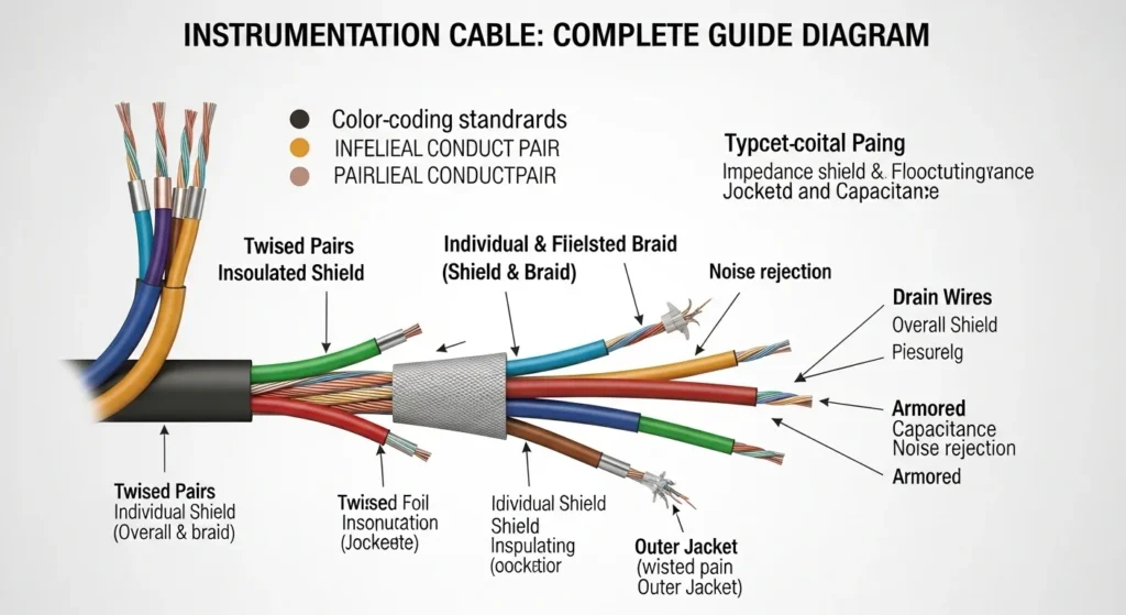
Instrumentation cables are carefully designed with multiple protective layers and conductive elements to ensure accurate, stable, and interference-free signal transmission. Each component performs a specific function that helps protect electrical signals from noise, mechanical damage, moisture, heat, and harsh industrial environments. Understanding these components makes it easier to select the right cable for industrial automation, process control, power plants, and instrumentation systems.
Conductor
The conductor is the core component of an instrumentation cable that carries electrical signals from sensors, transmitters, and field instruments to control equipment such as PLCs, DCS systems, and monitoring devices. Since instrumentation signals are typically low-voltage and low-current, the conductor must provide excellent electrical conductivity with minimal signal loss.
The most commonly used conductor materials include:
- Bare copper for high electrical conductivity
- Tinned copper for improved corrosion resistance
- Stranded conductors for greater flexibility
- Solid conductors for fixed installations
Copper is widely preferred because it offers low resistance, excellent signal quality, and long service life.
Insulation
Each conductor is individually covered with an insulation layer that prevents electrical leakage, short circuits, and signal interference between adjacent conductors. The insulation also protects the conductor from heat, chemicals, moisture, and mechanical stress.
Common insulation materials include:
- PVC (Polyvinyl Chloride)
- XLPE (Cross-linked Polyethylene)
- PE (Polyethylene)
- LSZH (Low Smoke Zero Halogen) for enhanced fire safety
The choice of insulation depends on operating temperature, voltage rating, flexibility, and environmental conditions.
Twisted Pair Construction
Instrumentation cables often use a twisted pair design, where two insulated conductors are twisted together at regular intervals. This construction minimizes electromagnetic interference (EMI) and reduces signal distortion caused by nearby electrical equipment.
Key benefits of twisted pair construction include:
- Reduces electromagnetic interference (EMI)
- Minimizes crosstalk between cable pairs
- Improves signal accuracy
- Enhances communication reliability over long distances
Twisted pair construction is one of the primary reasons instrumentation cables maintain stable signal transmission in electrically noisy industrial environments.
Shielding
Shielding is a protective metallic layer surrounding one or more conductor pairs. Its purpose is to block external electromagnetic and radio frequency interference, ensuring that sensitive instrumentation signals remain accurate and noise-free.
Common shielding types include:
- Aluminum foil shielding
- Copper braid shielding
- Foil and braid combination shielding
- Individual pair shielding
- Overall cable shielding
Effective shielding is especially important in power plants, oil and gas facilities, manufacturing industries, and process automation systems where electrical noise is common.
Drain Wire
Many shielded instrumentation cables include a drain wire that runs alongside the shielding layer. It provides an easy and reliable grounding connection, allowing unwanted electrical noise captured by the shield to safely dissipate to earth.
Benefits of a drain wire include:
- Simplifies shield grounding
- Improves EMI protection
- Reduces installation time
- Enhances overall signal stability
Filler Materials
Fillers are non-conductive materials placed between conductor pairs to maintain the cable’s round shape and provide additional mechanical stability. They also reduce internal movement that could damage conductors over time.
Common filler materials include:
- Polypropylene
- Cotton yarn
- PVC fillers
Inner Sheath (Bedding)
The inner sheath, also called bedding, surrounds the insulated conductors and shielding to hold all internal components securely together. It provides an additional protective layer before armoring is applied.
Its primary functions include:
- Maintains cable structure
- Protects internal components
- Improves mechanical strength
- Serves as a cushion beneath the armor layer
Armoring (Optional)
Armoring is an optional protective layer used in installations where cables may be exposed to physical damage. It protects the cable from crushing, impact, abrasion, and rodent attacks while extending its service life.
Common armor types include:
- Steel Wire Armor (SWA)
- Steel Tape Armor (STA)
- Aluminum Wire Armor (AWA)
Armored instrumentation cables are commonly installed underground, outdoors, industrial plants, and hazardous environments.
Outer Sheath (Cable Jacket)
The outer sheath is the cable’s final protective covering. It shields all internal components from environmental and mechanical damage while ensuring long-term durability.
The outer sheath protects against:
- Moisture
- Dust
- Chemicals
- UV radiation
- Oils
- Heat
- Abrasion
- Mechanical stress
Common outer sheath materials include PVC, PE, LSZH, and polyurethane, depending on the application’s environmental requirements.
Why These Components Matter
Every component of an instrumentation cable contributes to reliable signal transmission and long service life. The conductor carries the signal, insulation prevents electrical faults, twisted pairs reduce interference, shielding blocks electrical noise, drain wires improve grounding, fillers maintain cable shape, inner sheaths provide structural support, armoring resists mechanical damage, and the outer sheath protects the cable from environmental hazards. Together, these components ensure safe, accurate, and uninterrupted operation in industrial instrumentation and automation systems.
6. Advantages of Instrumentation Cable: Benefits for Industrial Signal Transmission
Instrumentation cables are specifically designed to transmit low-voltage control and measurement signals with high accuracy and reliability. Their specialized construction, including twisted pairs, insulation, and shielding, makes them ideal for industrial automation, process control, and instrumentation systems. Below are the key advantages of using instrumentation cables.
Accurate Signal Transmission
Instrumentation cables are engineered to carry low-level electrical signals with minimal signal loss. This ensures accurate communication between field instruments, sensors, transmitters, and control systems, resulting in precise monitoring and process control.
Excellent Protection Against Electrical Noise
Most instrumentation cables include foil or braided shielding that blocks electromagnetic interference (EMI) and radio frequency interference (RFI). This shielding prevents external electrical noise from affecting sensitive measurement signals.
Reliable Communication in Industrial Environments
Industrial facilities often contain heavy electrical equipment that generates interference. Instrumentation cables provide stable and uninterrupted signal transmission, ensuring reliable communication between devices even in electrically noisy environments.
Improved System Accuracy and Stability
Clean signal transmission reduces measurement errors, false readings, and communication failures. This improves the overall stability, safety, and efficiency of industrial automation and control systems.
High Mechanical and Environmental Durability
Instrumentation cables are designed to withstand demanding industrial conditions, including exposure to moisture, chemicals, oils, heat, vibration, and mechanical stress. Optional armoring provides additional protection against physical damage.
Long Service Life
High-quality conductor materials, durable insulation, and protective outer sheaths increase the cable’s lifespan while reducing maintenance and replacement costs.
Flexible Installation Options
Instrumentation cables are available in shielded, unshielded, armored, unarmored, twisted pair, and multi-pair configurations, making them suitable for a wide range of industrial applications and installation environments.
Enhanced Safety
Many instrumentation cables use flame-retardant and Low Smoke Zero Halogen (LSZH) materials that improve fire safety by reducing smoke and toxic gas emissions during a fire.
7. Disadvantages and Limitations of Instrumentation Cable
Although instrumentation cables offer many advantages, they also have certain limitations that should be considered during cable selection and system design.
Higher Initial Cost
Instrumentation cables are generally more expensive than ordinary electrical cables because they include specialized features such as shielding, twisted pairs, high-quality insulation, and protective jackets.
More Complex Installation
Shielded and armored instrumentation cables require proper installation techniques. Incorrect cable termination or grounding can reduce shielding effectiveness and negatively impact signal quality.
Sensitive to Improper Grounding
The shielding system must be grounded correctly to prevent ground loops and electrical noise. Poor grounding practices can introduce interference instead of eliminating it.
Not Suitable for High-Power Transmission
Instrumentation cables are designed to carry low-voltage control and measurement signals rather than high-current electrical power. Using them for power transmission can damage the cable and compromise system performance.
Larger Cable Size for Multi-Pair Designs
Multi-pair instrumentation cables contain several twisted pairs within a single jacket, making them thicker and heavier than standard cables. This may require additional space for routing and cable management.
Requires Skilled Maintenance
Testing, troubleshooting, and repairing instrumentation cables often require specialized equipment and experienced technicians to maintain signal integrity and system reliability.
While instrumentation cables have a higher cost and require careful installation, their ability to provide accurate signal transmission, superior noise immunity, long service life, and reliable industrial communication makes them the preferred choice for modern process control, automation, and instrumentation systems. Selecting the appropriate cable type and following proper installation practices helps maximize performance and minimize operational issues.
8. Applications of Instrumentation Cable: Where and Why It Is Used
Instrumentation cables are widely used in industries that require accurate, reliable, and interference-free transmission of control and measurement signals. They connect field instruments such as sensors, transmitters, and controllers to monitoring and automation systems. Their shielding and twisted-pair construction make them ideal for environments with high electrical noise and demanding operating conditions.
Industrial Automation
Instrumentation cables are essential in industrial automation systems, where they transmit signals between field devices and control equipment. They help ensure accurate monitoring, efficient machine operation, and reliable communication throughout the production process.
Common applications include:
- Sensors
- Pressure transmitters
- Temperature transmitters
- Flow meters
- PLC (Programmable Logic Controller) systems
- DCS (Distributed Control Systems)
- Control panels
- Motor control centers (MCCs)
Power Plants
Power generation facilities rely on instrumentation cables to connect measuring instruments with monitoring and control systems. These cables provide stable signal transmission, helping operators maintain safe and efficient plant operation.
They are commonly used for:
- Temperature sensors
- Pressure transmitters
- Flow meters
- Level sensors
- Turbine monitoring
- Generator protection systems
- Boiler control systems
Oil and Gas Industry
The oil and gas sector operates in harsh environments where accurate monitoring and reliable communication are essential. Instrumentation cables are designed to withstand heat, moisture, chemicals, and mechanical stress while maintaining signal integrity.
Typical applications include:
- Oil refineries
- Offshore drilling platforms
- Petrochemical plants
- Pipeline monitoring systems
- Tank farms
- Compressor stations
- Gas processing facilities
Chemical and Petrochemical Plants
Chemical processing industries require continuous monitoring of pressure, temperature, flow, and liquid levels. Instrumentation cables ensure accurate data transmission between field instruments and process control equipment.
Common uses include:
- Process control systems
- Reactor monitoring
- Chemical dosing systems
- Safety shutdown systems
- Hazardous area instrumentation
Building Automation Systems
Modern commercial buildings use instrumentation cables to connect intelligent monitoring and control devices. These systems improve energy efficiency, occupant comfort, and building safety.
Applications include:
- HVAC control systems
- Building Management Systems (BMS)
- Fire alarm and detection systems
- Smoke detection systems
- Access control systems
- Security and CCTV monitoring
- Lighting automation
Water and Wastewater Treatment Plants
Water treatment facilities depend on instrumentation cables to transmit signals from monitoring devices that control treatment processes and water quality.
Typical applications include:
- Pump control systems
- Flow monitoring
- Water level measurement
- pH sensors
- Chlorine monitoring
- SCADA systems
Pharmaceutical and Food Processing Industries
Industries with strict quality and hygiene standards require precise process control. Instrumentation cables provide reliable communication between measuring instruments and automated production systems.
They are commonly used in:
- Pharmaceutical manufacturing
- Food processing plants
- Beverage production
- Sterile process control
- Quality monitoring systems
Mining and Heavy Industries
Mining operations and heavy industrial plants use armored instrumentation cables in harsh environments where cables must withstand vibration, impact, dust, and mechanical damage.
Applications include:
- Conveyor monitoring systems
- Crusher control systems
- Mining equipment
- Material handling systems
- Industrial safety monitoring
Renewable Energy Systems
Instrumentation cables are increasingly used in renewable energy projects to connect monitoring devices and control systems.
Common applications include:
- Solar power plants
- Wind farms
- Battery energy storage systems
- Power monitoring equipment
- Grid automation systems
Instrumentation cables play a vital role in modern industrial and commercial facilities by providing accurate, stable, and interference-free signal transmission. Their applications extend across industrial automation, power plants, oil and gas, chemical processing, water treatment, smart buildings, renewable energy systems, mining, and manufacturing industries. Their durability, shielding, and high signal integrity make them indispensable for reliable process monitoring and control.
9. Comparison Section
Difference Between Instrumentation Cable and Power Cable
| Feature | Instrumentation Cable | Power Cable |
|---|---|---|
| Purpose | Signal transmission | Power transmission |
| Voltage Level | Low voltage signals | High voltage power |
| Shielding | Usually shielded | Often unshielded |
| Conductor Size | Small conductors | Large conductors |
| Applications | Sensors and control systems | Electrical power distribution |
Understanding the difference between instrumentation cable and power cable helps engineers choose the correct cable type.
8. Applications of Instrumentation Cable: Industrial Uses and Real-World Applications
Instrumentation cables are widely used in industries that require precise, reliable, and interference-free transmission of low-voltage control and measurement signals. They connect field instruments, sensors, transmitters, analyzers, and controllers to automation systems such as PLCs, DCS, and SCADA. Their twisted-pair construction and shielding protect sensitive signals from electromagnetic interference (EMI), making them essential for modern industrial operations.
Industrial Automation and Process Control
Industrial automation is one of the largest applications of instrumentation cables. They transmit signals between field devices and control systems, enabling automated monitoring, control, and data acquisition.
Common applications include:
- Sensors
- Pressure transmitters
- Temperature transmitters
- Flow meters
- Level transmitters
- PLC (Programmable Logic Controller) systems
- DCS (Distributed Control Systems)
- Control panels
- Motor Control Centers (MCCs)
- SCADA systems
Instrumentation cables help improve production efficiency, process accuracy, and operational safety.
Power Generation Plants
Power plants rely on instrumentation cables for continuous monitoring and control of electrical and mechanical equipment. Accurate signal transmission helps maintain safe operation and efficient power generation.
Typical applications include:
- Boiler control systems
- Steam turbine monitoring
- Generator protection systems
- Temperature measurement
- Pressure monitoring
- Flow measurement
- Water level control
- Vibration monitoring
- Alarm and protection systems
Oil and Gas Industry
Instrumentation cables are extensively used in upstream, midstream, and downstream oil and gas operations. These environments require cables that can withstand heat, chemicals, moisture, vibration, and harsh weather while maintaining reliable signal transmission.
Common applications include:
- Oil refineries
- Offshore drilling platforms
- Petrochemical plants
- Pipeline monitoring systems
- Tank farms
- Compressor stations
- Gas processing plants
- Pumping stations
- Instrument junction boxes
Chemical and Petrochemical Plants
Chemical processing facilities depend on accurate instrumentation to maintain product quality, safety, and process efficiency. Instrumentation cables provide reliable communication between field instruments and control equipment.
Typical applications include:
- Process control systems
- Reactor monitoring
- Pressure control
- Temperature monitoring
- Flow measurement
- Chemical dosing systems
- Safety shutdown (ESD) systems
- Hazardous area instrumentation
Building Automation and Smart Buildings
Modern commercial and residential buildings use instrumentation cables to connect intelligent building management systems. These systems improve energy efficiency, security, and occupant comfort.
Applications include:
- HVAC control systems
- Building Management Systems (BMS)
- Fire alarm systems
- Smoke detection systems
- Access control systems
- CCTV surveillance
- Lighting automation
- Energy monitoring systems
Water and Wastewater Treatment Plants
Water treatment facilities use instrumentation cables to monitor and control water processing operations. Accurate signal transmission ensures efficient treatment and regulatory compliance.
Typical applications include:
- Pump control systems
- Water level measurement
- Flow monitoring
- Pressure monitoring
- pH analyzers
- Chlorine analyzers
- SCADA monitoring systems
- Filtration control
- Wastewater treatment automation
Pharmaceutical and Food Processing Industries
Highly regulated industries require precise process control to maintain product quality and safety. Instrumentation cables support continuous monitoring throughout the manufacturing process.
Common applications include:
- Pharmaceutical manufacturing
- Food processing plants
- Beverage production
- Cleanroom monitoring
- Sterile processing systems
- Temperature-controlled production
- Quality assurance systems
- Packaging automation
Mining, Cement, and Heavy Industries
Heavy industries operate in demanding environments where cables must withstand dust, vibration, moisture, and mechanical impact. Armored instrumentation cables provide additional protection in these applications.
Typical applications include:
- Conveyor belt monitoring
- Crusher control systems
- Material handling equipment
- Cement manufacturing plants
- Mining machinery
- Industrial safety systems
- Equipment monitoring
Renewable Energy Systems
Renewable energy installations use instrumentation cables to monitor equipment performance and optimize energy production. Reliable signal transmission improves system efficiency and operational reliability.
Applications include:
- Solar power plants
- Wind farms
- Battery energy storage systems (BESS)
- Inverter monitoring
- Transformer monitoring
- Power quality monitoring
- Grid automation systems
Marine and Offshore Applications
Marine vessels and offshore platforms require durable instrumentation cables that resist saltwater, humidity, vibration, and mechanical stress.
Common applications include:
- Ship automation systems
- Offshore oil platforms
- Engine monitoring
- Navigation equipment
- Marine control panels
- Safety and alarm systems
Manufacturing Industries
Instrumentation cables are widely used across manufacturing facilities for machine control, quality monitoring, and automated production lines.
Applications include:
- CNC machines
- Robotics
- Packaging machines
- Assembly lines
- Industrial sensors
- Production monitoring
- Machine condition monitoring
Why Instrumentation Cables Are Essential in Modern Industries
Instrumentation cables are indispensable in industries where accurate data transmission, reliable communication, and process automation are critical. Their specialized construction—including twisted pairs, shielding, durable insulation, and optional armoring—ensures protection against electromagnetic interference, mechanical damage, moisture, and harsh environmental conditions.
From industrial automation and power plants to oil and gas, pharmaceuticals, renewable energy, smart buildings, mining, and manufacturing, instrumentation cables provide the dependable signal transmission required for safe, efficient, and uninterrupted industrial operations.
11. Common Instrumentation Cable Problems and Troubleshooting Solutions
Although instrumentation cables are designed for reliable and long-term performance, improper installation, harsh environmental conditions, and equipment failures can sometimes cause signal transmission problems. Understanding the common issues and their solutions helps maintain accurate measurements, minimize downtime, and improve the reliability of industrial control systems.
Why Is Signal Interference (Noise) Occurring?
Signal interference is one of the most common problems in instrumentation systems. Electrical noise can distort low-level signals, leading to inaccurate measurements and unstable control system performance.
Possible Causes:
- Damaged or missing cable shielding
- Instrumentation cables installed too close to power cables
- Improper or multiple-point shield grounding
- High electromagnetic interference (EMI) from nearby equipment
- Faulty cable routing
Solutions:
- Use shielded instrumentation cables in high-noise environments.
- Maintain proper separation between power and instrumentation cables.
- Ground the cable shield correctly according to manufacturer recommendations.
- Route cables away from motors, transformers, and high-voltage equipment.
- Inspect the shielding for damage and replace the cable if necessary.
Why Are Instrumentation Signals Fluctuating?
Fluctuating or unstable signals usually indicate problems with the cable, connectors, grounding, or connected instruments. These variations can affect process accuracy and system reliability.
Possible Causes:
- Loose cable terminals
- Damaged conductor insulation
- Electrical noise or EMI
- Moisture entering cable joints
- Defective sensors or transmitters
- Poor grounding connections
Solutions:
- Tighten all cable terminals and connectors.
- Inspect insulation for cracks or damage.
- Test the cable using a multimeter or insulation resistance tester.
- Verify proper grounding and shielding.
- Replace damaged connectors or faulty field instruments.
Why Is the Signal Lost Completely?
A complete signal loss usually indicates a serious electrical or mechanical fault within the cable or connected equipment. Immediate troubleshooting is necessary to restore communication.
Possible Causes:
- Broken conductor
- Severely damaged cable
- Loose or disconnected terminals
- Faulty sensor or transmitter
- Open circuit in the signal path
- Damaged PLC or control system input
Solutions:
- Perform a continuity test to identify open circuits.
- Check all cable connections and terminal blocks.
- Inspect the cable for physical damage.
- Test the connected sensor or transmitter.
- Replace damaged cables or faulty devices if required.
Why Is Crosstalk Occurring Between Cable Pairs?
Crosstalk occurs when signals from one conductor interfere with another conductor inside the same cable. This issue is more common in poorly installed or damaged multi-pair cables.
Possible Causes:
- Damaged insulation between pairs
- Incorrect cable termination
- Excessive cable bending
- Poor-quality cable construction
Solutions:
- Use high-quality twisted-pair instrumentation cables.
- Follow proper cable termination practices.
- Avoid excessive bending during installation.
- Replace damaged cable sections.
Why Is the Cable Overheating?
Although instrumentation cables carry low-voltage signals, overheating may occur due to improper installation or unsuitable operating conditions.
Possible Causes:
- Exposure to excessive ambient temperature
- Installation near heat sources
- Incorrect cable selection
- Damaged insulation
Solutions:
- Use cables with the correct temperature rating.
- Keep cables away from boilers, furnaces, and hot pipelines.
- Replace damaged insulation immediately.
- Follow manufacturer installation guidelines.
How Can Instrumentation Cable Problems Be Prevented?
Preventive maintenance significantly improves cable reliability and extends service life.
Best Practices:
- Perform regular visual inspections.
- Test cable continuity and insulation resistance periodically.
- Ensure proper grounding and shield termination.
- Keep instrumentation cables separated from power cables.
- Protect cables from moisture, chemicals, and mechanical damage.
- Replace damaged cables before complete failure occurs.
- Use the correct cable type for the application and environment.
Summary
Most instrumentation cable problems result from poor installation, damaged insulation, incorrect grounding, electrical interference, or mechanical damage. Regular inspection, proper cable routing, correct shield grounding, and preventive maintenance help ensure accurate signal transmission, reduce downtime, and improve the reliability of industrial automation and process control systems.
12. Future Trends in Instrumentation Cable Technology and Industrial Automation
As industries move toward smart manufacturing, Industry 4.0, and digital automation, instrumentation cable technology continues to evolve. Future instrumentation cables will offer improved signal integrity, enhanced durability, higher data transmission speeds, and intelligent monitoring capabilities. These innovations will help industries achieve greater efficiency, safety, and reliability in process control and automation systems.
Smart Instrumentation Cables with Embedded Monitoring
One of the most significant developments is the integration of smart monitoring technology into instrumentation cables. Future cables may include embedded sensors capable of continuously monitoring cable health and operating conditions.
These intelligent cables can monitor:
- Cable temperature
- Signal quality
- Insulation condition
- Moisture intrusion
- Mechanical stress
- Cable aging
Real-time monitoring allows maintenance teams to identify potential problems before cable failure occurs, reducing downtime and maintenance costs.
Advanced Shielding Technology
As industrial environments become increasingly complex, electromagnetic interference (EMI) and radio frequency interference (RFI) continue to grow. Future instrumentation cables will use advanced shielding materials that provide even greater protection against electrical noise.
Emerging shielding technologies include:
- Multi-layer foil shielding
- High-density copper braid shielding
- Composite shielding materials
- Hybrid EMI/RFI protection
These improvements will ensure highly accurate signal transmission in factories, power plants, and high-voltage industrial environments.
Fire-Resistant and Fire-Survival Instrumentation Cables
Safety regulations are driving the development of fire-resistant instrumentation cables that continue operating during fire emergencies. These cables help maintain communication with critical control and safety systems even under extreme conditions.
Future fire-resistant cables will offer:
- Extended circuit integrity during fire
- Low smoke emission
- Zero halogen materials
- Improved flame resistance
- Enhanced emergency system reliability
They are expected to become increasingly common in power plants, tunnels, airports, hospitals, offshore platforms, and industrial facilities.
Eco-Friendly and Sustainable Cable Materials
Manufacturers are increasingly focusing on environmentally friendly cable construction. Future instrumentation cables will use recyclable and low-impact materials without compromising electrical performance or durability.
Sustainable developments include:
- Recyclable insulation materials
- Low Smoke Zero Halogen (LSZH) compounds
- Reduced toxic emissions
- Energy-efficient manufacturing processes
- Environmentally responsible production techniques
These innovations support global sustainability goals while improving workplace safety.
High-Speed Data Transmission
Modern industrial automation requires faster communication between field devices, controllers, and monitoring systems. Future instrumentation cables will be designed to support higher-speed data transmission while maintaining excellent signal integrity.
Benefits include:
- Faster industrial communication
- Reduced signal latency
- Improved automation performance
- Enhanced real-time monitoring
- Greater compatibility with advanced control systems
These improvements will support increasingly complex industrial automation networks.
Integration with Industry 4.0 and Industrial IoT (IIoT)
Industry 4.0 is transforming manufacturing through interconnected devices and intelligent automation. Future instrumentation cables will play an essential role in Industrial Internet of Things (IIoT) networks by providing reliable communication between smart sensors, controllers, and cloud-based monitoring platforms.
Applications include:
- Smart factories
- Predictive maintenance systems
- Digital process monitoring
- Remote equipment diagnostics
- Industrial data analytics
- Connected manufacturing systems
Improved Mechanical Strength and Environmental Protection
Future cable designs will provide greater resistance to harsh operating conditions, increasing service life and reducing maintenance requirements.
Expected improvements include:
- Better UV resistance
- Increased chemical resistance
- Higher temperature ratings
- Improved abrasion resistance
- Enhanced flexibility
- Stronger armored cable construction
These features will make instrumentation cables even more reliable in demanding industrial environments.
Hybrid Instrumentation and Communication Cables
Manufacturers are developing hybrid cables capable of carrying both instrumentation signals and industrial communication data within a single cable assembly. This reduces installation complexity and lowers infrastructure costs.
Potential benefits include:
- Simplified cable management
- Reduced installation costs
- Less cable congestion
- Improved system integration
- Higher installation efficiency
The future of instrumentation cable technology is closely linked to the growth of smart factories, Industry 4.0, Industrial IoT (IIoT), renewable energy, and advanced process automation. Innovations such as embedded cable monitoring, advanced shielding, fire-resistant construction, eco-friendly materials, hybrid cable designs, and high-speed industrial communication will improve system reliability, operational safety, and maintenance efficiency. As industrial automation continues to advance, instrumentation cables will remain a critical component for accurate signal transmission and intelligent control systems.
13. Conclusion
Instrumentation cables are a critical part of modern industrial control and monitoring systems. They allow accurate transmission of low-level signals from sensors and instruments to control equipment without interference.
Understanding the instrumentation cable working principle, types, components, and applications is essential for electrical students, engineers, and technicians working in industrial environments. These cables ensure reliable communication between measuring devices and control systems, helping maintain safe and efficient operations.
Although instrumentation cables may have higher cost and require proper installation techniques, their advantages in signal accuracy, interference protection, and durability make them indispensable in industries such as power generation, oil and gas, automation, and manufacturing.
As industrial technology continues to advance, instrumentation cables will play an even more important role in supporting modern smart monitoring and control systems.