
Imagine you are at home and you plug a mobile charger into a socket. Your phone starts charging smoothly. But one day, the charger becomes hot, charging is slow, or it stops working completely. You may wonder: What went wrong? Is the electricity weak? Is the wire damaged? Or is there a problem inside the charger?
The answer to these questions is connected to three basic electrical concepts: Voltage, Current, and Resistance.
These three terms are the foundation of all electrical and electronic systems. Every machine, device, and power system works based on their relationship. Without understanding them, it is very difficult to design circuits, repair faults, or work safely.
For students, technicians, engineers, and beginners, learning these concepts is the first step in electrical education. They help you understand how electricity flows, how much power is used, and why some devices fail.
In this article, you will learn what voltage, current, and resistance are, their working principle, types, components, advantages, applications, and future trends in simple and clear language.
2. What is Voltage, Current, and Resistance?
Voltage
Voltage is one of the most important electrical quantities used in all types of electrical systems. It is defined as the electrical potential difference between two points in a circuit that causes electric current to flow. In simple terms, voltage is the “pressure” that pushes electric charges through a conductor. It is measured in volts (V) and represented by the symbol “V” in electrical formulas. Without voltage, no current can flow, which means electrical devices cannot operate.
In everyday life, voltage is used in homes, industries, and power systems. For example, household appliances like fans, lights, and refrigerators operate on standard voltage levels such as 230V in many countries. Different devices require different voltage levels depending on their design and power needs. Low voltage systems are used for small electronics, while high voltage systems are used for power transmission over long distances to reduce energy loss.
Voltage is also an important factor in electrical safety. If the voltage is too high, it can damage equipment and create serious hazards like electric shock or fire. If it is too low, devices may not work properly or may operate inefficiently. That is why engineers carefully design electrical systems with proper voltage regulation and protection devices.
In electrical engineering, voltage is related to current and resistance through Ohm’s Law. This relationship helps in calculating how much current will flow in a circuit based on applied voltage and resistance. Voltage can be AC (Alternating Current) or DC (Direct Current). AC voltage changes direction periodically, while DC voltage flows in one constant direction.
Overall, voltage is the backbone of electrical systems. Understanding it is essential for students, engineers, and technicians because it helps in designing safe, efficient, and reliable electrical installations in homes, industries, and power networks.
2. Voltage, Current, and Resistance: Definitions and Relationship
To understand electric current, you must first understand the three basic electrical quantities: voltage, current, and resistance. These three quantities work together in every electrical circuit and are connected by Ohm’s Law.
Whether you are studying electrical engineering or working as a technician, understanding their relationship is essential for analyzing and designing electrical systems.
What is Voltage (V)?
Voltage is the electrical potential difference between two points in a circuit. It provides the force (or electrical pressure) that pushes electrons through a conductor.
Without voltage, electric current cannot flow.
- Symbol: V
- SI Unit: Volt (V)
- Measuring Instrument: Voltmeter
Example
A 12V battery supplies 12 volts of electrical pressure to push current through the connected circuit.
What is Current (I)?
Current is the flow of electric charge through a conductor. In metallic conductors, this flow consists of moving electrons.
Simply put, current is the rate at which electric charge passes through a point in a circuit.
Current only flows when:
- A voltage source is available.
- A complete (closed) circuit exists.
- Symbol: I
- SI Unit: Ampere (A)
- Measuring Instrument: Ammeter
Example
If a light bulb draws 2 amperes, it means 2 coulombs of electric charge pass through the circuit every second.
What is Resistance (R)?
Resistance is the property of a material that opposes the flow of electric current. It limits how easily electrons can move through a conductor.
The higher the resistance, the lower the current for a given voltage.
- Symbol: R
- SI Unit: Ohm (Ω)
- Measuring Instrument: Ohmmeter or Multimeter
Example
A long, thin wire has higher resistance than a short, thick wire made from the same material.
Relationship Between Voltage, Current, and Resistance (Ohm’s Law)
These three electrical quantities are related by Ohm’s Law, one of the most fundamental laws in electrical engineering.
Ohm’s Law Formula
V = I × R
Where:
- V = Voltage (Volts)
- I = Current (Amperes)
- R = Resistance (Ohms)
From this equation:
- Current increases when voltage increases.
- Current decreases when resistance increases.
- Voltage is directly proportional to current.
- Current is inversely proportional to resistance.
This relationship helps engineers calculate unknown electrical values and design safe electrical circuits.
3. How Electric Current Works (Working Principle)
The working principle of electric current is based on the movement of electrons through a closed electrical circuit under the influence of voltage.
When a voltage source such as a battery or generator is connected to a complete circuit, it creates an electric field that pushes electrons through the conductor. The moving electrons carry electrical energy from the source to the load, where it is converted into useful forms such as light, heat, or mechanical energy.
If the circuit is open or broken, current cannot flow because there is no complete path for the electrons.
Step-by-Step Working Principle of Electric Current
Step 1: The Power Source Produces Voltage
An electrical source, such as a battery, generator, or power supply, creates a voltage difference between its terminals.
This voltage provides the energy required to move electrons.
Step 2: Voltage Pushes the Electrons
The voltage acts like electrical pressure, forcing free electrons inside the conductor to move from one point to another.
Without voltage, electrons remain stationary.
Step 3: Electrons Flow Through the Conductor
Once the circuit is closed, electrons begin moving through the wire, creating an electric current.
This continuous movement of electrons is known as electric current.
Step 4: Resistance Limits the Current
Every conductor offers some resistance to the flow of electrons.
Resistance opposes current flow, reducing the amount of current that can pass through the circuit.
Higher resistance means lower current.
Step 5: Current Reaches the Electrical Load
The flowing current delivers electrical energy to the connected load, such as:
- Light bulbs
- Electric fans
- Motors
- Heaters
- Electronic devices
The load converts electrical energy into useful forms like light, heat, or mechanical motion.
Step 6: Current Returns to the Source
After passing through the load, the current returns to the power source, completing the electrical circuit and allowing continuous operation.
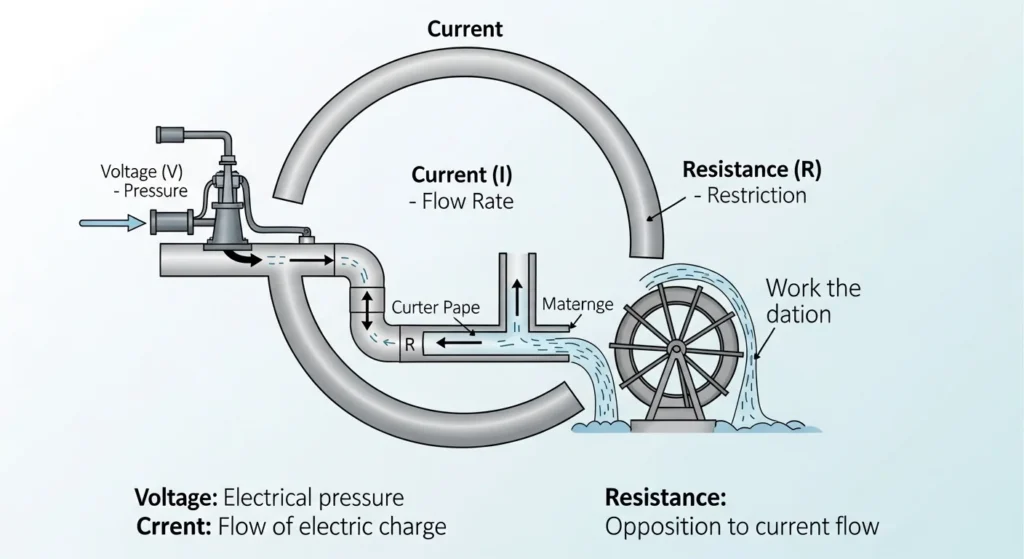
Simple Analogy: Electric Current as Water Flow
A water pipeline provides an easy way to understand how electricity works.
| Water System | Electrical System |
|---|---|
| Water tank | Voltage source (Battery/Generator) |
| Water pressure | Voltage |
| Water flow | Current |
| Narrow pipe | Resistance |
| Water wheel | Electrical Load |
If the water tank is higher, the pressure increases.
Similarly, higher voltage pushes more current through the circuit.
If the pipe becomes narrower, less water flows.
Likewise, higher resistance reduces the electric current.
Key Points to Remember
- Voltage provides the force that moves electrons.
- Current is the flow of electric charge.
- Resistance opposes the flow of current.
- A complete (closed) circuit is necessary for current to flow.
- Current carries electrical energy from the source to the load.
- Ohm’s Law explains the relationship between voltage, current, and resistance.
- Proper control of current ensures safe and efficient operation of electrical systems.
This structure is more SEO-friendly because it uses descriptive headings such as “What is Voltage,” “What is Current,” “What is Resistance,” “Relationship Between Voltage, Current, and Resistance,” and “How Electric Current Works (Working Principle)”, while naturally incorporating relevant keywords throughout the content.
4. Types of Voltage, Current, and Resistance
Voltage, current, and resistance can be classified into different types based on how they behave and where they are used. Understanding these classifications helps students and engineers select the right electrical components for different applications.
Types of Voltage
Voltage is mainly classified into Direct Current (DC) Voltage and Alternating Current (AC) Voltage.
1. Direct Current (DC) Voltage
DC voltage is a type of voltage whose polarity remains constant over time. The positive and negative terminals do not change, so the current flows in only one direction.
DC voltage is commonly produced by batteries, solar panels, and DC power supplies.
Characteristics
- Constant polarity
- Stable voltage output
- Current flows in one direction
- Suitable for electronic circuits
Common Applications
- Mobile phones
- Laptops
- Power banks
- LED lighting
- Electric vehicles
- Solar energy systems
Example: A mobile phone battery provides approximately 5 V DC for charging.
2. Alternating Current (AC) Voltage
AC voltage is a type of voltage that continuously changes its magnitude and direction at regular intervals.
Most countries supply AC power because it can be transmitted efficiently over long distances.
Characteristics
- Changes direction periodically
- Voltage varies in magnitude
- Operates at 50 Hz or 60 Hz
- Suitable for power transmission and distribution
Common Applications
- Residential electrical supply
- Industrial power systems
- Air conditioners
- Electric motors
- Household appliances
Example: A typical household wall outlet supplies approximately 220–240 V AC in many countries.
Types of Current
Electric current is classified into two main types depending on the direction of electron flow.
1. Direct Current (DC)
Direct Current (DC) flows continuously in one direction from the negative terminal to the positive terminal (electron flow is opposite to conventional current direction).
DC provides a steady and constant supply of electrical energy.
Characteristics
- Flows in one direction only
- Constant polarity
- Stable current
- Easy to store in batteries
Common Applications
- Electronic circuits
- Mobile phones
- Computers
- Battery-powered devices
- Solar photovoltaic systems
Example: A flashlight powered by batteries uses DC current.
2. Alternating Current (AC)
Alternating Current (AC) changes its direction periodically, usually many times every second.
Because of its efficiency, AC is the standard form of electricity used in homes, industries, and power grids.
Characteristics
- Changes direction continuously
- Voltage and current vary with time
- Easily transmitted over long distances
- Operates at 50 Hz or 60 Hz
Common Applications
- Home electrical wiring
- Industrial machines
- Air conditioners
- Refrigerators
- Power distribution systems
Example: Electricity supplied by the utility company is AC current.
Types of Resistance
Resistance can be classified according to whether its value remains constant or changes under different operating conditions.
1. Fixed Resistance
A fixed resistor has a constant resistance value that cannot be changed during normal operation.
It is one of the most commonly used components in electronic and electrical circuits.
Characteristics
- Constant resistance value
- Simple and reliable
- Low cost
- Available in many resistance ratings
Common Applications
- Electronic circuits
- LED current limiting
- Voltage divider circuits
- Signal processing
Example: Carbon film resistor, metal film resistor, and wire-wound resistor.
2. Variable Resistance
A variable resistor allows the resistance value to be adjusted manually or automatically to control current or voltage.
Variable resistors are also known as potentiometers or rheostats, depending on their application.
Characteristics
- Adjustable resistance
- Controls current or voltage
- Easy to operate
- Suitable for variable electrical loads
Common Applications
- Volume controls
- Light dimmers
- Fan speed controllers
- Laboratory equipment
Example: The volume knob on an audio amplifier uses a potentiometer.
3. Non-Linear Resistance
A non-linear resistor has a resistance value that changes with voltage, current, temperature, or light intensity instead of remaining constant.
These components are widely used for sensing and circuit protection.
Characteristics
- Resistance changes with operating conditions
- Used for sensing and protection
- Suitable for automatic control circuits
Common Applications
- Surge protection
- Temperature sensing
- Light sensing
- Voltage regulation
Examples
- Thermistor (temperature-dependent resistor)
- Photoresistor (Light Dependent Resistor or LDR)
- Varistor (voltage-dependent resistor)
Note: A diode is not a resistor. Although its current-voltage relationship is non-linear, it is a semiconductor device, not a type of resistance. Therefore, thermistors, LDRs, and varistors are more accurate examples of non-linear resistance.
Quick Comparison of Voltage, Current, and Resistance Types
| Electrical Quantity | Types | Common Applications |
|---|---|---|
| Voltage | DC Voltage, AC Voltage | Batteries, Power Supply, Household Electricity |
| Current | Direct Current (DC), Alternating Current (AC) | Electronics, Power Distribution |
| Resistance | Fixed Resistance, Variable Resistance, Non-Linear Resistance | Electronic Circuits, Sensors, Control Systems |
This updated section is technically accurate, beginner-friendly, and SEO-optimized while correcting the common mistake of listing a diode as a type of resistance.
5. Main Components of an Electrical Circuit
Every electrical circuit consists of several essential components that work together to generate, control, transmit, and use electrical energy. Understanding these components helps students and engineers analyze, design, and troubleshoot electrical systems effectively.
1. Voltage Source
A voltage source is the component that provides electrical energy to the circuit. It creates the potential difference (voltage) that pushes electrons through the conductor, allowing current to flow.
Without a voltage source, no current can flow in a closed circuit.
Common Examples
- Battery
- Generator
- Solar panel
- DC power supply
- AC mains supply
Functions
- Supplies electrical energy
- Creates the voltage required for current flow
- Powers electrical and electronic devices
2. Conductor (Electrical Wire)
A conductor provides the path through which electric current flows from the source to the load.
Good conductors have very low electrical resistance, allowing electricity to flow efficiently.
Common Examples
- Copper wire
- Aluminum cable
- Copper busbar
Functions
- Carries electric current
- Connects all circuit components
- Minimizes power losses
3. Resistor
A resistor is an electrical component that limits or controls the flow of current in a circuit.
Resistors protect sensitive electronic components and help regulate voltage and current.
Common Types
- Fixed resistor
- Variable resistor (Potentiometer)
- Rheostat
Functions
- Limits current flow
- Divides voltage
- Protects electronic components
- Controls electrical circuits
4. Load
A load is any electrical device that consumes electrical energy and converts it into another form of energy, such as light, heat, sound, or mechanical motion.
Common Examples
- Light bulb
- Electric fan
- Heater
- Electric motor
- Air conditioner
- Television
Functions
- Consumes electrical power
- Performs useful work
- Converts electrical energy into usable energy
5. Switch
A switch controls the flow of current by opening or closing an electrical circuit.
When the switch is closed (ON), current flows. When it is open (OFF), the circuit is interrupted.
Common Examples
- ON/OFF switch
- Push-button switch
- Toggle switch
- Rotary switch
Functions
- Controls electrical circuits
- Turns equipment ON or OFF
- Improves safety during maintenance
6. Measuring Instruments
Electrical measuring instruments are used to monitor voltage, current, resistance, and other electrical quantities.
These instruments help technicians and engineers test, troubleshoot, and maintain electrical systems.
Common Instruments
- Voltmeter (Measures Voltage)
- Ammeter (Measures Current)
- Ohmmeter (Measures Resistance)
- Multimeter (Measures multiple electrical parameters)
- Clamp Meter (Measures current without disconnecting the circuit)
Functions
- Measure electrical quantities
- Diagnose circuit faults
- Verify safe operation
- Improve maintenance accuracy
Summary of Main Electrical Components
| Component | Primary Function | Common Examples |
|---|---|---|
| Voltage Source | Supplies electrical energy | Battery, Generator, Power Supply |
| Conductor | Carries electric current | Copper Wire, Aluminum Cable |
| Resistor | Controls current flow | Fixed Resistor, Potentiometer |
| Load | Consumes electrical energy | Bulb, Fan, Motor |
| Switch | Opens or closes the circuit | Toggle Switch, Push Button |
| Measuring Instruments | Measure electrical parameters | Voltmeter, Ammeter, Multimeter |
Together, these components form the foundation of every electrical and electronic system.
6. Advantages of Understanding Voltage, Current, and Resistance
Understanding the relationship between voltage, current, and resistance is essential for designing safe, efficient, and reliable electrical systems. These concepts form the basis of electrical engineering and are applied in almost every electrical installation.
Key Advantages
1. Simplifies Circuit Design
Knowledge of voltage, current, and resistance helps engineers design electrical circuits that operate efficiently and safely.
2. Improves Electrical Safety
Understanding current limits and voltage levels reduces the risk of electric shock, overheating, and electrical fires.
3. Helps Select Proper Wire Sizes
Current calculations allow engineers to choose cables that can safely carry electrical loads without overheating.
4. Enables Correct Equipment Selection
Electrical calculations help in selecting suitable:
- Circuit breakers
- Fuses
- Switches
- Transformers
- Power supplies
5. Reduces Energy Loss
Proper resistance and cable selection minimize voltage drops and power losses, improving overall system efficiency.
6. Prevents Equipment Damage
Correct electrical calculations protect motors, transformers, appliances, and electronic equipment from excessive current or voltage.
7. Simplifies Troubleshooting
Understanding these basic electrical quantities helps technicians quickly identify wiring faults, overloads, and voltage problems.
8. Forms the Foundation of Electrical Engineering
Almost every electrical calculation—from Ohm’s Law to complex power system analysis—depends on voltage, current, and resistance.
7. Limitations and Practical Challenges
Although voltage, current, and resistance are fundamental electrical concepts, practical electrical systems often involve additional factors that make circuit analysis more complex.
1. Ohm’s Law Is Not Applicable to All Components
Ohm’s Law works well for linear components such as ordinary resistors but does not accurately describe the behavior of many semiconductor devices like diodes and transistors.
2. Resistance Changes with Temperature
The resistance of most conductors increases as temperature rises, affecting current flow and circuit performance.
3. Voltage Drop in Long Cables
Long transmission lines and cables experience voltage drops because of conductor resistance.
4. Heat Losses
Whenever current flows through a conductor, part of the electrical energy is converted into heat due to resistance.
5. Complex AC Circuits Require Additional Analysis
Alternating current (AC) circuits also involve reactance, impedance, capacitance, inductance, and power factor, making analysis more complicated than simple DC circuits.
6. Measurement Errors
Incorrect measuring instruments, poor calibration, or improper testing methods can produce inaccurate electrical measurements.
7. Poor Wiring Can Affect Performance
Loose connections, damaged insulation, undersized cables, and poor installation practices increase resistance and reduce system efficiency.
Note: Understanding these limitations helps engineers apply electrical principles more accurately in real-world installations.
8. Applications of Voltage, Current, and Resistance
Voltage, current, and resistance are used in virtually every electrical and electronic system. Their proper understanding is essential for designing, operating, and maintaining modern technology.
Residential Applications
These electrical quantities are used daily in homes for the safe operation of electrical appliances and wiring systems.
Common Applications
- Home lighting systems
- Ceiling fans
- Air conditioners
- Refrigerators
- Water heaters
- Mobile chargers
- Extension boards
- Household electrical wiring
Industrial Applications
Industrial facilities rely on accurate electrical calculations to ensure reliable operation of heavy machinery and power distribution systems.
Common Applications
- Electric motors
- Motor control centers (MCC)
- Power distribution panels
- Industrial automation
- Manufacturing equipment
- Electrical substations
- Control systems
Electronic Applications
Electronic circuits require precise control of voltage, current, and resistance for proper operation.
Common Applications
- Mobile phones
- Computers
- Printed Circuit Boards (PCBs)
- Sensors
- Microcontrollers
- Communication devices
- Consumer electronics
Renewable Energy Systems
Renewable energy technologies depend on proper electrical design to maximize efficiency and system reliability.
Common Applications
- Solar photovoltaic (PV) systems
- Wind turbines
- Battery storage systems
- Solar charge controllers
- Inverters
- Hybrid power systems
Electric Vehicles (EVs)
Electric vehicles use carefully controlled voltage and current to power electric motors, charging systems, and battery management systems.
Applications
- EV battery packs
- Fast charging stations
- Motor controllers
- Battery Management Systems (BMS)
Smart Homes and Building Automation
Modern smart buildings use electrical sensors and intelligent controllers that continuously monitor voltage and current.
Applications
- Smart lighting
- Energy management systems
- Smart circuit breakers
- Home automation
- Smart meters
Data Centers and IT Infrastructure
Reliable electrical power is critical for data centers and communication networks.
Applications
- Uninterruptible Power Supplies (UPS)
- Server power systems
- Backup generators
- Power monitoring systems
Robotics and Automation
Industrial robots and automated production systems require accurate electrical control for safe and efficient operation.
Applications
- Robotic arms
- PLC systems
- Servo motors
- Industrial automation equipment
Why These Concepts Matter
Voltage, current, and resistance are the building blocks of every electrical system. From powering a simple LED to operating large industrial plants, these three quantities determine how electrical energy is generated, transmitted, controlled, and safely used. A strong understanding of these fundamentals helps students, technicians, and engineers design efficient circuits, troubleshoot faults, improve safety, and optimize the performance of modern electrical systems.
9. Comparison Section: Voltage vs Current vs Resistance
Comparison Table
| Feature | Voltage (V) | Current (I) | Resistance (R) |
| Meaning | Electrical pressure | Flow of electrons | Opposition to flow |
| Unit | Volt (V) | Ampere (A) | Ohm (Ω) |
| Function | Pushes electrons | Transfers energy | Controls current |
| Role | Source force | Result | Control element |
| Dependency | Depends on I & R | Depends on V & R | Depends on V & I |
Explanation
Voltage pushes, current flows, and resistance controls.
All three are equally important.
This shows the difference between voltage, current, and resistance.
10. Selection Guide: How to Choose the Right Voltage, Current, and Resistance
Selecting the correct values of voltage, current, and resistance is essential for designing safe, efficient, and reliable electrical circuits. Proper selection helps prevent overheating, equipment damage, excessive power loss, and electrical hazards.
Whether you are a beginner or an engineering student, following a systematic approach will help you choose the right electrical components.
Step 1: Identify the Electrical Device Requirements
Before designing or connecting any circuit, check the electrical specifications of the device.
Verify the following information from the nameplate or technical datasheet:
- Rated voltage
- Rated current
- Power rating (Watts)
- Operating frequency (for AC equipment)
Example
An electric fan may be rated at:
- Voltage: 220 V AC
- Current: 0.6 A
- Power: 120 W
These values determine the components that should be used.
Step 2: Apply Ohm’s Law
Use Ohm’s Law to calculate the unknown electrical quantity.
Formula
V = I × R
Where:
- V = Voltage (Volts)
- I = Current (Amperes)
- R = Resistance (Ohms)
This formula helps determine the correct resistor values, current flow, and voltage requirements.
Example
If:
- Voltage = 24 V
- Resistance = 12 Ω
Then,
Current = V ÷ R = 24 ÷ 12 = 2 A
Step 3: Select the Correct Components
Choose electrical components that match or exceed the circuit requirements.
Components to Select
- Correct wire size
- Proper resistor value
- Suitable fuse or circuit breaker
- Appropriate power supply
- Switches with adequate current rating
Selecting the right components improves safety and increases system reliability.
Step 4: Provide a Safety Margin
Electrical components should never be operated continuously at their maximum ratings.
A common engineering practice is to allow approximately 20–25% additional capacity, where appropriate and in accordance with equipment specifications and applicable electrical standards.
This helps accommodate temporary load increases and improves component life.
Step 5: Consider Cable Size
The cable must safely carry the expected current without excessive heating or voltage drop.
Factors affecting cable selection include:
- Current-carrying capacity
- Cable length
- Voltage drop
- Installation method
- Ambient temperature
Step 6: Verify Power Ratings
Ensure that all components can safely handle the expected electrical power.
For resistors:
Power (P) = V × I
or
P = I²R
Choose a resistor with a power rating higher than the calculated value.
Tips for Beginners
- Always read the equipment nameplate before making electrical connections.
- Use a digital multimeter to measure voltage, current, and resistance.
- Never overload electrical circuits.
- Use correctly rated cables, fuses, and circuit breakers.
- Tighten all electrical connections securely.
- Practice solving Ohm’s Law calculations regularly.
- Follow electrical safety rules at all times.
- Disconnect the power supply before working on a circuit.
11. Common Problems and Solutions (FAQs)
Understanding common electrical problems helps students and technicians troubleshoot circuits safely and efficiently.
Q1: Why does my electrical wire become hot?
A wire usually becomes hot because excessive current is flowing through it or the wire is too small for the connected load.
Possible Causes
- Overloaded circuit
- Undersized cable
- Loose electrical connections
- Poor-quality conductor
Solution
- Reduce the electrical load.
- Use the correct wire size.
- Tighten loose connections.
- Replace damaged cables if necessary.
Q2: Why is the voltage lower than expected?
Low voltage occurs when the supply voltage drops before reaching the load.
Possible Causes
- Long cable runs
- Loose terminals
- Overloaded circuits
- Low utility supply voltage
Solution
- Inspect and tighten electrical connections.
- Use larger cable sizes for long distances.
- Reduce excessive loading.
- Verify the incoming supply voltage.
Q3: Why does the fuse keep blowing?
A fuse blows because the current flowing through it exceeds its rated capacity.
Possible Causes
- Short circuit
- Overload
- Faulty appliance
- Incorrect fuse rating
Solution
- Disconnect faulty equipment.
- Locate and repair the fault.
- Replace the fuse with the correct rating.
- Never install an oversized fuse.
Q4: Why is my electrical device operating slowly?
Electrical equipment may operate inefficiently when it receives insufficient voltage.
Possible Causes
- Low supply voltage
- Excessive voltage drop
- Weak power source
- Overloaded electrical circuit
Solution
- Measure the supply voltage.
- Check cable size and connections.
- Reduce unnecessary loads.
- Ensure the equipment is receiving its rated voltage.
Q5: Why does resistance change?
Resistance is not always constant. Many materials change resistance when operating conditions change.
Common Causes
- Temperature changes
- Material properties
- Aging of components
- Mechanical damage
Solution
- Use high-quality components.
- Select components suitable for the operating environment.
- Replace damaged resistors or conductors.
- Perform regular inspection and testing.
Q6: Why is the measured current different from the calculated value?
In real electrical systems, measured current may differ slightly from calculated values due to component tolerances, temperature changes, voltage fluctuations, and measurement accuracy.
Solution
- Use calibrated measuring instruments.
- Verify circuit connections.
- Measure the actual supply voltage.
- Consider component tolerances during calculations.
12. Future Trends in Voltage, Current, and Resistance Measurement
Advances in electrical engineering, automation, and digital technology are transforming how voltage, current, and resistance are measured, monitored, and controlled.
Modern electrical systems are becoming more intelligent, connected, and energy efficient.
1. Smart Electrical Sensors
Modern sensors continuously monitor voltage, current, temperature, and power consumption in real time.
Benefits
- Continuous monitoring
- Early fault detection
- Improved safety
- Higher system reliability
2. Digital Power Meters
Traditional analog meters are being replaced by intelligent digital meters that provide highly accurate measurements and advanced monitoring features.
Features
- High measurement accuracy
- Power quality monitoring
- Energy consumption analysis
- Data logging
- Remote communication
3. AI-Based Electrical Monitoring
Artificial Intelligence (AI) is increasingly used to analyze electrical data and predict equipment failures before they occur.
Advantages
- Predictive maintenance
- Fault prediction
- Reduced downtime
- Improved energy efficiency
- Better equipment reliability
4. Wireless Measurement Systems
Wireless technologies allow electrical measurements to be collected remotely without extensive wiring.
Applications
- Smart homes
- Industrial automation
- Renewable energy systems
- Building management systems
5. Internet of Things (IoT)
IoT technology connects electrical devices to cloud platforms for real-time monitoring and control.
Benefits
- Remote access
- Instant fault alerts
- Automatic data collection
- Centralized monitoring
- Improved maintenance planning
6. Smart Energy Management Systems
Modern electrical installations use intelligent energy management systems to optimize electricity consumption and improve efficiency.
Applications
- Smart buildings
- Data centers
- Manufacturing plants
- Commercial facilities
Future Outlook
The future of electrical engineering is moving toward smart, connected, and automated systems. Technologies such as AI, IoT, digital measuring instruments, wireless monitoring, and smart sensors are making electrical systems safer, more efficient, and easier to maintain.
Despite these technological advances, the fundamental concepts of voltage, current, and resistance will continue to form the foundation of electrical engineering. Every electrical calculation, circuit design, and power system analysis begins with a clear understanding of these three essential quantities.
13. Conclusion
Voltage, current, and resistance are the building blocks of electrical engineering. They explain how electricity is produced, controlled, and used in every system. In this article, we discussed their definition, working principle, types, components, advantages, disadvantages, applications, comparison, selection guide, common problems, and future trends.
For beginners and students, mastering these concepts is essential for safe and successful electrical work. They help in designing circuits, solving faults, and improving system efficiency. Without this knowledge, advanced electrical topics become very difficult.
As a senior engineer would advise: always respect voltage limits, control current properly, and manage resistance wisely. With strong basics, you can grow confidently in the electrical field.