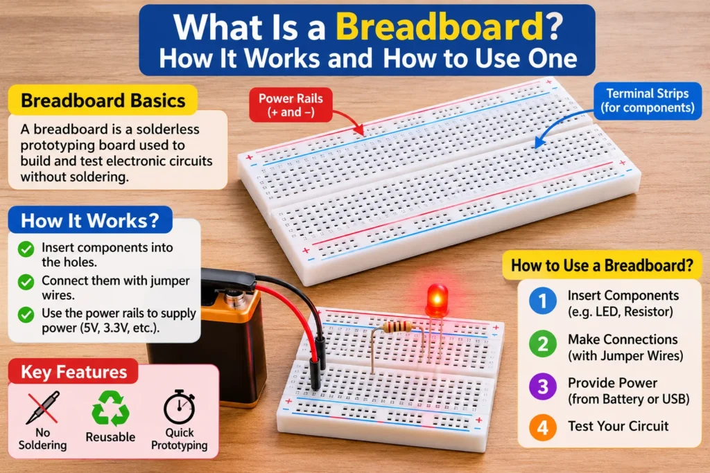

A breadboard is the fastest way to build an electronic circuit without soldering. Push the legs of resistors, LEDs, and chips into its holes, connect a battery or a power supply, and the circuit works. Change your mind and you can pull the parts out and start again in seconds. That is why almost every electronics beginner, student, and hobbyist owns one, and why engineers still reach for one to test an idea before committing it to a printed circuit board.
This guide explains what a breadboard is, how the hidden metal clips inside it connect your parts, the main types and sizes, how to build your first circuit on one, and the mistakes that cause most breadboard failures.
What Is a Breadboard?
A breadboard is a reusable board for building temporary electronic circuits without soldering. Its plastic top is covered with a grid of small holes, spaced 0.1 inch (2.54 mm) apart. That spacing matches the pins of integrated circuits and the leads of most through-hole components, so parts drop straight in.
Under each hole is a spring-metal clip. Push a component lead or a jumper wire into a hole and the clip grips it and makes an electrical connection. Pull it out and the connection is gone. No solder, no heat, no permanent change, which makes the breadboard the standard tool for prototyping: trying out a circuit, testing it, and changing it until it works.
The name comes from the early days of electronics, when hobbyists really did build circuits on wooden bread boards, nailing components and wires to a board used for slicing bread. The modern solderless breadboard, with its plastic body and spring clips, became popular in the 1970s and has barely changed since.
How a Breadboard Works
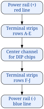
The key to a breadboard is knowing which holes are connected to each other underneath. The board is divided into two areas: the terminal strips in the middle and the power rails along the edges.
Each terminal strip is a row of five holes joined by one metal clip, so all five holes in a row are the same electrical point, or node. Push two component leads into the same row and they are connected. Push them into different rows and they are not. The rows are usually labeled with letters A to E on one side of the center channel and F to J on the other, and numbered along the board, so you can describe a connection as “row 12, holes A to E”.
A wide channel runs down the middle of the board and splits the terminal strips into two halves. That gap is sized to fit a dual in-line package (DIP) integrated circuit: the chip sits across the channel with its pins on opposite sides, so the two rows of pins are not shorted together. Each pin then has its own row of five holes to connect to.
The power rails are the long strips of holes that run along the top and bottom edges of the board. All the holes in one rail are connected together, so the whole rail carries one voltage, usually marked with a red line for positive and a blue line for negative or ground. You connect your power supply to the rails once, and then any part of the circuit can pick up power from the nearest rail. On larger boards the rails are split in the middle, so check for a break in the red and blue lines before you assume a rail runs the full length.
Types of Breadboards
Solderless breadboards are the reusable type described above. They come in three common sizes: mini boards with about 170 tie points (a tie point is one hole), half-size boards with about 400 tie points, and full-size boards with about 830 tie points. A full-size board is enough for most hobby projects, including circuits with several chips. Mini boards are handy for small tests and fit in a pocket.
Solderable breadboards, also called perfboards or stripboards, look similar but the connections are permanent. Perfboard has isolated holes and you solder wires between them, while stripboard has copper strips under the rows that you cut where you do not want a connection. These are used when a prototype works and needs to become a permanent circuit, or when a breadboard cannot handle the current or frequency.
Some breadboards add extras: binding posts for the power supply, a built-in power supply with 5 V and 3.3 V outputs, or a metal base plate. These are convenient but not essential; a plain full-size board and a separate supply do the same job.
Breadboard Layout: What Goes Where
A typical full-size breadboard has about 830 tie points arranged as two power rails at the top, two at the bottom, and two blocks of terminal strips in the middle, separated by the center channel. The holes are numbered in columns, usually 1 to 63, and lettered in rows, A to E and F to J.
Place integrated circuits across the center channel so each pin gets its own row. Place other components anywhere in the terminal strips, keeping their leads short and flat against the board. Use the power rails for the supply voltages and ground, and use short jumper wires to carry signals between rows. Solid-core 22 AWG wire is the standard for jumpers: it is stiff enough to push into the holes and thick enough to grip firmly. Stranded wire frays and makes poor contact, so avoid it.
How to Use a Breadboard: Build an LED Circuit
Start with the power off. Connect the positive lead of a 5 V supply to the red power rail and the negative lead to the blue rail. Check that the rails are continuous along the board; if your board has a break in the middle of a rail, bridge it with a jumper wire.
Build this simple LED circuit to learn the layout. Place a 220 ohm resistor with one leg in a terminal-strip row and the other leg in a different row. Push the long leg of a red LED (the anode) into the same row as one end of the resistor, and the short leg (the cathode) into a row connected to the blue ground rail. Then run a jumper from the red power rail to the free end of the resistor.
The resistor limits the current through the LED. A red LED drops about 2 V, so the resistor sees 5 V minus 2 V, which is 3 V. With a 220 ohm resistor, the current is 3 / 220, which is about 13.6 mA. That is bright enough to see clearly and safely below the usual 20 mA limit for a small LED. If you used a 150 ohm resistor, the current would be 3 / 150, or 20 mA, which is the maximum most small LEDs are rated for, so 220 ohms is the safer everyday choice.
Switch the power on and the LED should light. If it does not, switch off and check: is the LED the right way around, is the resistor in the right rows, and is every lead pushed fully into its hole? Most first-circuit failures are a lead that is one row out or not pushed in far enough.

Breadboard vs Perfboard vs PCB
A breadboard is for testing. A perfboard is for a permanent one-off circuit. A printed circuit board (PCB) is for a finished product or a circuit you will build more than once. The table below compares them.
| Board | Connections | Best for | Reusable |
|---|---|---|---|
| Solderless breadboard | Spring clips, no solder | Prototyping and learning | Yes |
| Perfboard / stripboard | Soldered wires or copper strips | Permanent one-off circuits | No |
| Printed circuit board (PCB) | Copper traces, soldered | Finished products, many copies | No |
Common Breadboard Mistakes and Limitations
Loose connections are the most common problem. A lead that is not pushed in fully, a jumper that is too thin, or a worn clip after years of use can all cause a circuit that works when you press on it and fails when you let go. Push every lead in firmly until it stops, and replace jumpers that feel loose.
Current and voltage limits matter too. The small spring clips and thin metal strips are made for signals and small loads, so keep currents below about 1 A and stick to low-voltage DC circuits such as 5 V or 12 V. Do not use a breadboard for mains voltage or for motors and heaters that draw heavy current.
Breadboards also add stray capacitance between adjacent rows, roughly a few picofarads, and the long, looping wires add inductance. That is harmless at audio and hobby speeds, but it makes breadboards unreliable for radio-frequency and fast digital circuits, where a PCB is the right tool. Keep wires short and run power and ground close together to reduce noise.
Applications of Breadboards
Breadboards are the standard tool for learning electronics. Students build their first LED, transistor, and timer circuits on them, and Arduino projects almost always start on a breadboard before anything is soldered.
Engineers use them to test a new sensor, try a different component value, or prove that a circuit idea works before designing a PCB. Because nothing is permanent, a failed idea costs minutes, not a new board.
They are also used for quick repairs and demonstrations: a sensor, a display, and a microcontroller can be wired together on a breadboard in a few minutes to show a customer or a class how a product will behave.
Related reading: Potentiometer: How It Works, Types, and Applications
Related reading: What Is a Resistor and How Does It Work?
Frequently Asked Questions
How many holes are connected in a breadboard row?
Five. Each terminal strip row is one metal clip joining five holes, so all five holes in the same row are the same electrical point.
Can I use a breadboard with mains voltage?
No. Breadboards are for low-voltage DC circuits only, typically 5 V or 12 V, with currents below about 1 A. Mains voltage is dangerous on a breadboard and the clips are not rated for it.
Why is my breadboard circuit not working?
The most common causes are a component lead in the wrong row, a lead not pushed in fully, a reversed LED or diode, or a break in the middle of a power rail. Check each connection row by row with the power off.
What size breadboard should I buy first?
A full-size board with about 830 tie points. It has room for several chips and a power supply section, and it costs only a little more than a half-size board.
Can I leave a circuit on a breadboard permanently?
You can, but it is not reliable long term. Clips loosen, wires get knocked, and dust builds up. Once a circuit works, move it to perfboard or a PCB for permanent use.
Conclusion
A breadboard turns circuit building into something you can do with your hands in minutes: push the parts in, connect the power, and test. Learn the layout — five-hole rows, the center channel for chips, and the power rails along the edges — and you can build almost any low-voltage circuit without touching a soldering iron. When the circuit works and needs to last, move it to perfboard or a PCB. For the full background, see https://en.wikipedia.org/wiki/Breadboard