Imagine the electrical wiring inside a modern home. When you switch on a fan in one room, the lights in another room continue to work normally. If one bulb burns out, the other appliances still operate. This convenient and reliable operation is possible because most household electrical systems use a parallel circuit.
Parallel circuits are one of the most fundamental concepts in electrical engineering. From home wiring systems to complex industrial control panels, this circuit configuration plays a critical role in distributing electricity safely and efficiently.
For electrical students, engineers, technicians, and beginners, understanding how parallel circuits work is essential. Without this knowledge, it becomes difficult to design safe electrical systems, troubleshoot faults, or calculate power distribution.
In this article, you will learn the parallel circuit working principle, its types, components, advantages, and limitations. We will also explore parallel circuit applications, practical troubleshooting tips, and the difference between series and parallel circuits. The goal is to explain the topic clearly and practically, just like a senior electrical engineer guiding a junior technician.
2. What is a Parallel Circuit?
A parallel circuit is an electrical circuit in which multiple components are connected across the same voltage source in separate branches.
In simple terms, each component has its own path to receive electrical current.
Key Characteristics
- Voltage across each branch is the same.
- Current divides among different branches.
- If one branch fails, the rest of the circuit continues to operate.
Simple Example
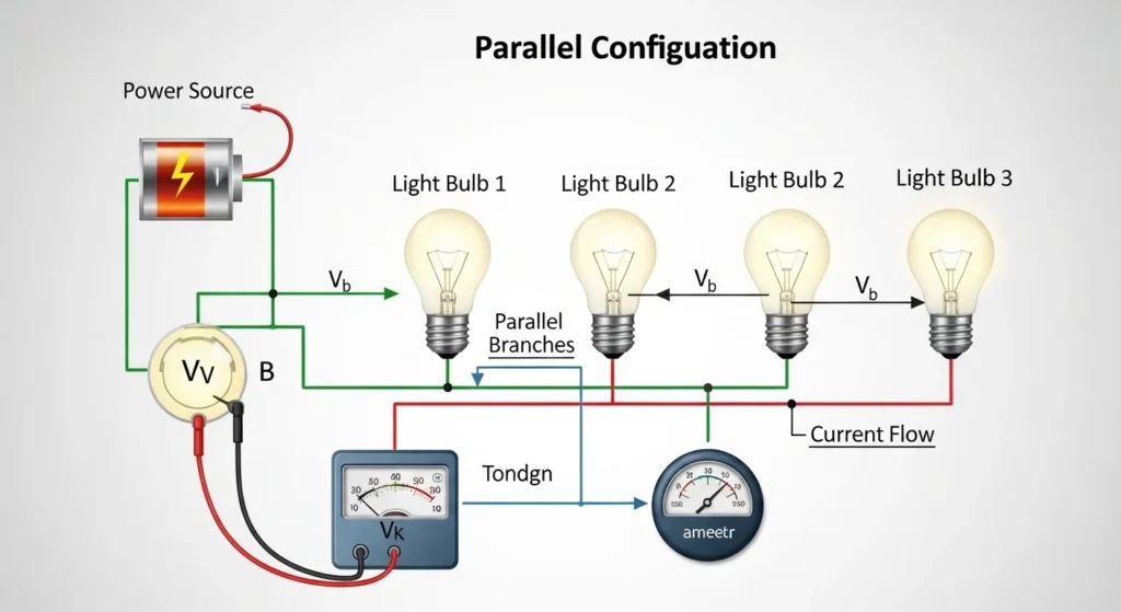
Consider three light bulbs connected to a battery:
- In a parallel circuit, each bulb is connected directly to the battery terminals.
- Each bulb receives the same voltage.
- If one bulb burns out, the others remain lit.
This is why parallel circuits are widely used in residential wiring and electrical distribution systems.
Parallel Circuit Working Principle: Detailed Explanation
Introduction
The working principle of a parallel circuit is based on providing multiple paths for electric current to flow from the power source. Instead of following a single path, the current divides into several branches, allowing each connected component to operate independently. This feature makes parallel circuits highly reliable and widely used in electrical systems.
Voltage in a Parallel Circuit
In a parallel circuit, the power source such as a battery or supply provides the same voltage across all branches. All components are connected between the same two points, so every branch receives equal voltage. Because of this, each device operates independently without affecting the performance of others.
Current Division in Parallel Circuit
When the circuit is switched on, the total current from the source splits into different paths depending on the resistance of each branch. A branch with lower resistance allows more current to flow, while a branch with higher resistance allows less current to flow. However, the total current is always equal to the sum of all branch currents.
Formula:
Total Current = I₁ + I₂ + I₃ + … + Iₙ
Each component uses its own share of current while still receiving the same voltage from the source.
Real-Life Example (Water Analogy)
A simple way to understand this principle is by comparing it to a water distribution system in a building. The main pipe carries water from the source and then divides into several smaller pipes that supply different apartments. Each apartment receives water independently, and if one pipe is blocked or damaged, the others continue to supply water without interruption. Similarly, in a parallel circuit, each branch works independently and does not depend on the others.
In conclusion, the working principle of a parallel circuit is based on dividing current into multiple independent paths while maintaining the same voltage across all components. This ensures stable, efficient, and reliable operation in electrical systems.
4. Types / Classification of Parallel Circuits
Parallel circuits can be classified based on the type of components used.
Pure Resistive Parallel Circuit – Explanation in Simple Words
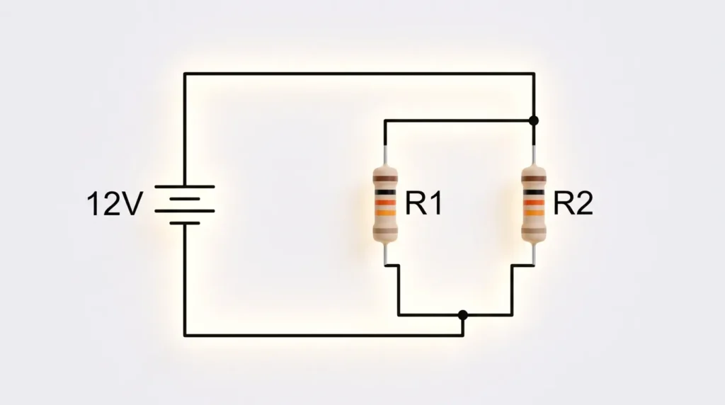
This type contains only resistors connected in parallel.
Characteristics:
- Voltage remains constant across each resistor
- Current divides according to resistance values
- Common in basic electrical experiments
A Pure Resistive Parallel Circuit is an electrical circuit in which only resistors are connected in parallel with each other, and there are no inductors or capacitors involved. In this type of circuit, all resistors are directly connected across the same two points of the power supply, which means every resistor receives the same voltage from the source. This is one of the most basic and important types of electrical circuit used in many practical applications.
In a parallel resistive circuit, the main feature is that the voltage remains the same across all resistors, while the current is divided among different branches. Each resistor draws current independently based on its own resistance value. According to Ohm’s Law, a resistor with lower resistance will draw more current, while a resistor with higher resistance will draw less current. However, the total current coming from the source is equal to the sum of all individual branch currents.
Another important concept in this circuit is the equivalent resistance. In a pure resistive parallel circuit, the total or equivalent resistance is always less than the smallest resistor present in the circuit. As more resistors are added in parallel, the overall resistance keeps decreasing, which allows more current to flow from the power source. The formula used to calculate total resistance is the reciprocal sum of all individual resistances.
This type of circuit is widely used in real-life electrical systems because it provides stability and reliability. If one resistor or device fails in a parallel circuit, the other components continue to work normally without any interruption. That is why parallel circuits are commonly used in household wiring systems, lighting systems, and electrical distribution boards where independent operation of devices is required.
In conclusion, a pure resistive parallel circuit is a simple but very important electrical arrangement where voltage stays constant, current splits among branches, and total resistance decreases as more resistors are added. It is highly useful in practical electrical systems due to its safety, efficiency, and independent working nature.
Parallel Circuit with Capacitors: Working Principle, Characteristics, and Applications
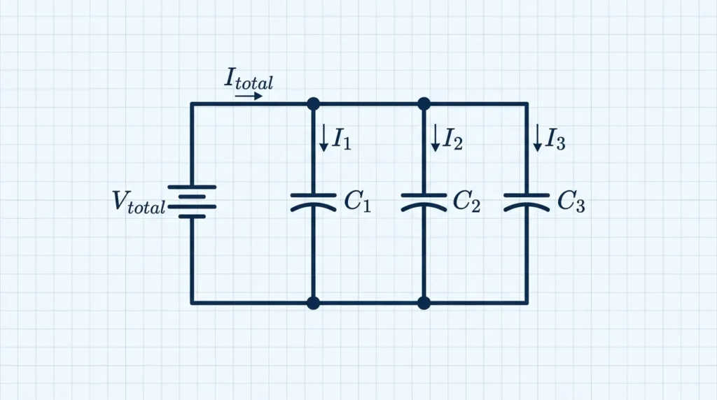
A Parallel Circuit with Capacitors is an electrical circuit in which two or more capacitors are connected across the same voltage source in separate branches. In this arrangement, each capacitor is connected directly across the supply terminals, meaning that every capacitor experiences the same voltage regardless of its capacitance value. Parallel capacitor circuits are widely used in electronic devices, power systems, communication equipment, filtering circuits, and energy storage applications because they provide increased capacitance, improved energy storage capability, and enhanced circuit performance.
When capacitors are connected in parallel, the voltage across each capacitor remains equal to the source voltage. However, the electrical charge stored by each capacitor depends on its capacitance value. Larger capacitors can store more charge than smaller ones when connected to the same voltage source. The total charge stored in the circuit is the sum of the charges stored by all individual capacitors. As a result, parallel capacitor connections are commonly used when greater energy storage capacity is required.
One of the most important characteristics of a parallel capacitor circuit is that the total equivalent capacitance increases as additional capacitors are added. Unlike resistors connected in parallel, where the equivalent resistance decreases, the equivalent capacitance of parallel capacitors is simply the sum of all individual capacitances. This allows engineers to achieve higher capacitance values by combining multiple capacitors together. The total capacitance is always greater than the capacitance of any single capacitor in the network.
Parallel capacitor circuits are commonly found in power supply systems where they help smooth voltage fluctuations and reduce electrical noise. In electronic circuits, they are used for filtering, signal coupling, decoupling, and energy storage purposes. Communication systems use parallel capacitors to improve signal quality and stabilize circuit operation. They are also widely used in renewable energy systems, battery backup units, and industrial control equipment where reliable energy storage is important.
One major advantage of parallel capacitor connections is their ability to increase total energy storage while maintaining the same operating voltage. They also improve voltage stability, reduce ripple in power supplies, and enhance the performance of sensitive electronic equipment. Additionally, if one capacitor fails in an open-circuit condition, the remaining capacitors can often continue functioning, improving system reliability.
However, engineers must carefully consider capacitor ratings, leakage currents, tolerance values, and physical space requirements when designing parallel capacitor networks. Proper component selection ensures safe operation and long-term reliability.
Because of their ability to store electrical energy, stabilize voltage, and improve circuit efficiency, parallel capacitor circuits play a vital role in modern electrical engineering, electronics, telecommunications, industrial automation, and power distribution systems. Their simplicity, flexibility, and effectiveness make them one of the most widely used capacitor configurations in practical electrical applications.
In this configuration, capacitors are connected in parallel.
Characteristics:
- Voltage across each capacitor is the same
- Total capacitance increases
- Used in filtering and energy storage circuits
Parallel Circuit with Inductors: Working Principle, Characteristics, and Applications
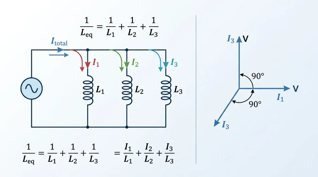
Inductors connected in parallel form this type of circuit.
Characteristics:
- Used in power electronics
- Important in AC circuits and filters
- Affects current flow and impedance
A Parallel Circuit with Inductors is an electrical circuit in which two or more inductors are connected across the same voltage source in separate branches. In this configuration, each inductor receives the same supply voltage, while the total current supplied by the source is divided among the individual branches according to the inductance values. Parallel inductor circuits are widely used in AC power systems, electronic filters, communication equipment, power supplies, transformers, and energy storage applications because they provide flexibility in controlling current flow and magnetic energy storage.
When inductors are connected in parallel, the voltage across each inductor remains identical to the source voltage. However, the current flowing through each branch depends on the inductive reactance of the inductor. Inductive reactance increases with both frequency and inductance value, meaning larger inductors generally allow less alternating current to flow compared to smaller inductors. As a result, current is distributed among the parallel branches based on the electrical characteristics of each inductor.
One important characteristic of parallel inductor circuits is their equivalent inductance. Unlike series-connected inductors, where total inductance increases, connecting inductors in parallel reduces the overall equivalent inductance of the circuit. This allows engineers to achieve specific inductance values that may not be available using a single component. The equivalent inductance is always smaller than the smallest individual inductor in the parallel network.
Parallel inductor circuits are commonly used in power electronics and communication systems. In switching power supplies, parallel inductors help distribute current more evenly and reduce component stress. In radio frequency and filter circuits, inductors connected in parallel are used to control frequency response and improve signal quality. Power distribution systems also utilize parallel inductive components to manage reactive power and improve electrical efficiency.
One major advantage of parallel inductors is increased current-handling capability. Multiple inductors can share the total load current, reducing heating and improving system reliability. Additionally, if designed properly, parallel inductors can improve efficiency, reduce electromagnetic interference, and enhance overall circuit performance. However, engineers must carefully consider magnetic coupling, current sharing, and component tolerances to ensure balanced operation.
Because of their ability to control current flow, store magnetic energy, and improve system performance, parallel circuits with inductors play a critical role in modern electrical engineering, power systems, telecommunications, industrial electronics, and advanced energy management applications.
Mixed Parallel Circuit (Series-Parallel Circuit): Working Principle, Structure, and Applications
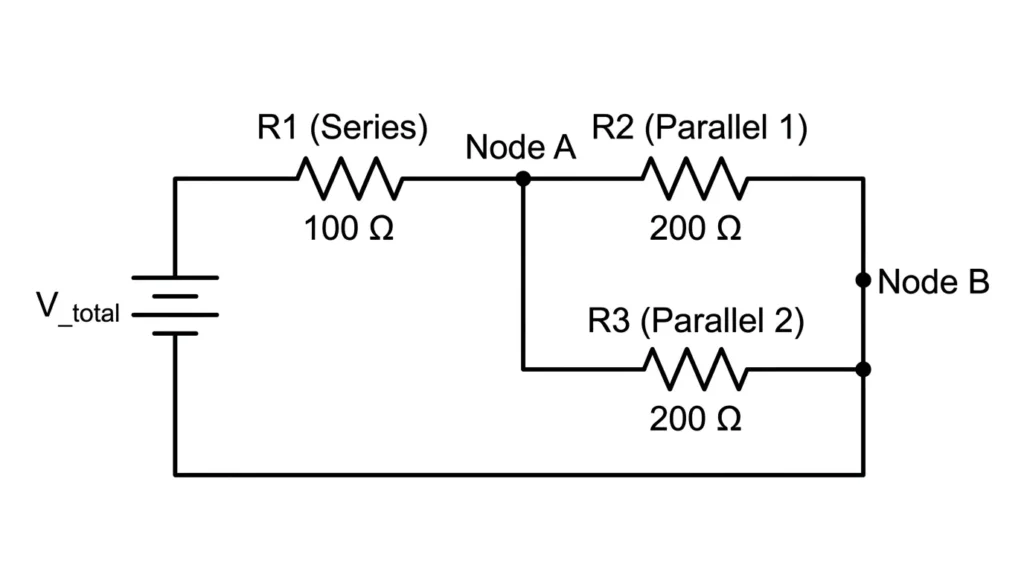
A mixed parallel circuit contains different components such as resistors, capacitors, and inductors.
This type is common in real electrical systems and electronic circuits.
A Mixed Parallel Circuit, commonly known as a Series-Parallel Circuit, is an electrical circuit that combines both series and parallel connections within a single electrical network. In this configuration, some components are connected in series while others are connected in parallel, allowing the circuit to take advantage of the benefits offered by both circuit types. Mixed parallel circuits are widely used in modern electrical and electronic systems because they provide greater flexibility in voltage distribution, current flow, power management, and circuit control. Most practical electrical installations found in homes, industries, automobiles, and electronic devices utilize series-parallel arrangements rather than purely series or purely parallel circuits.
In a mixed parallel circuit, electrical current may flow through a series section before splitting into multiple parallel branches. Components connected in series share the same current, while components connected in parallel receive the same voltage. This combination allows engineers to design circuits that can meet specific operational requirements while maintaining efficient performance. The behavior of voltage and current depends on the exact arrangement of components within the network.
One of the biggest advantages of mixed parallel circuits is their versatility. They allow multiple devices to operate independently while also incorporating common control and protection elements. For example, in residential electrical systems, lighting and appliance circuits are often connected in parallel, while switches, fuses, and circuit breakers may be connected in series with the loads they control. This arrangement ensures safe operation while maintaining reliable power distribution.
Mixed parallel circuits are extensively used in industrial automation systems, manufacturing equipment, communication devices, power distribution networks, and consumer electronics. In industrial environments, several machines may operate on parallel branches while sharing common protection and monitoring devices connected in series. This design improves reliability, simplifies maintenance, and enhances operational flexibility.
Analyzing a mixed parallel circuit is generally more complex than analyzing a simple series or parallel circuit. Engineers must calculate voltage drops, current distribution, equivalent resistance, and power consumption using electrical principles such as Ohm’s Law and Kirchhoff’s Circuit Laws. Despite the increased complexity, the benefits of improved flexibility, reliability, and efficiency make mixed parallel circuits one of the most important circuit configurations in electrical engineering.
Because they combine the strengths of both series and parallel circuits, mixed parallel circuits form the foundation of countless electrical and electronic applications. Their ability to provide efficient power distribution, independent device operation, and enhanced system control makes them essential in modern electrical technology.
Main Components of a Parallel Circuit
A parallel circuit is made up of several essential components that work together to distribute electrical energy safely and efficiently. Each component performs a specific function that helps ensure the proper operation of the electrical system. Understanding these components is important for students, electricians, technicians, and engineers because they form the foundation of most residential, commercial, and industrial electrical installations. Without these key elements, a parallel circuit would not be able to deliver power reliably to connected devices.
Power Source
The power source is the heart of a parallel circuit because it provides the electrical energy needed for the entire system to operate. It creates the voltage that drives electric current through the circuit and powers all connected loads.
Depending on the application, different types of power sources may be used. In small electronic circuits, batteries are commonly used because they provide portable direct current (DC) power. In industrial and commercial systems, generators and electrical power supplies are often used to deliver larger amounts of electrical energy. Residential buildings typically receive power from utility distribution networks.
Common Power Sources Include:
- Batteries
- Generators
- AC Power Supplies
- DC Power Supplies
- Solar Panels
- Electrical Utility Grids
In a parallel circuit, the power source supplies the same voltage to all connected branches, ensuring that each device receives the electrical energy required for proper operation.
Conductors (Electrical Wires)
Conductors are the pathways through which electric current flows throughout the circuit. They connect the power source, loads, switches, and protective devices, creating complete paths for electrical current.
Copper is the most widely used conductor material because it has excellent electrical conductivity, low resistance, high durability, and good corrosion resistance. Aluminum conductors are also used in certain applications where weight reduction and cost savings are important.
The size of the conductor is selected based on the amount of current the circuit must carry. Proper conductor sizing is essential because undersized wires can overheat and create safety hazards.
Functions of Conductors:
- Carry electrical current between components
- Connect all circuit branches
- Minimize energy losses
- Ensure safe power distribution
- Support efficient circuit operation
Well-designed conductor systems contribute significantly to the overall performance and reliability of a parallel circuit.
Electrical Loads
Electrical loads are the components that consume electrical energy and convert it into useful forms such as light, heat, motion, or sound. Loads are the devices that perform the actual work within the electrical system.
One of the major advantages of a parallel circuit is that each load operates independently while receiving the full supply voltage. If one load is switched off or fails, the other loads continue functioning normally.
Examples of Electrical Loads Include:
- Light Bulbs
- Ceiling Fans
- Electric Motors
- Televisions
- Computers
- Air Conditioners
- Heaters
- Refrigerators
- Industrial Machinery
- Electronic Equipment
The total current drawn from the power source depends on the number and power ratings of the connected loads.
Switches
Switches are control devices used to open or close electrical circuits. They allow users to control the flow of electricity and operate individual devices independently.
In a parallel circuit, switches are often installed in separate branches so that each load can be controlled without affecting other connected devices. For example, turning off one room light does not affect lights in other rooms because each branch has its own switching arrangement.
Types of Switches Commonly Used:
- Single-Pole Switches
- Double-Pole Switches
- Push Button Switches
- Toggle Switches
- Rotary Switches
- Smart Electronic Switches
Switches improve convenience, energy efficiency, and operational flexibility in electrical systems.
Protective Devices
Protective devices are critical safety components that protect electrical circuits, equipment, and users from dangerous conditions such as overloads, short circuits, and electrical faults.
When excessive current flows through the circuit, protective devices automatically interrupt the electrical supply before serious damage can occur. This helps prevent equipment failure, electrical fires, and personal injury.
Common Protective Devices Include:
- Circuit Breakers
- Fuses
- Residual Current Devices (RCDs)
- Ground Fault Circuit Interrupters (GFCIs)
- Overload Relays
In a parallel circuit, protective devices can often isolate only the affected branch, allowing the rest of the system to continue operating safely.
Junctions and Branch Connections
A unique feature of parallel circuits is the presence of junction points where the electrical current divides into multiple branches. These junctions allow several loads to be connected directly across the same voltage source.
At each junction:
- Current splits into different paths.
- Each branch receives the full supply voltage.
- Total circuit current equals the sum of all branch currents.
Properly designed junction connections ensure efficient power distribution and reliable circuit performance.
Measuring and Monitoring Devices
Many modern parallel circuits include instruments used to monitor electrical performance and system health.
Common measuring devices include:
- Voltmeters
- Ammeters
- Wattmeters
- Multimeters
- Energy Meters
- Power Quality Analyzers
These devices help technicians monitor voltage, current, power consumption, and system efficiency, making troubleshooting and maintenance easier.
Summary of Main Parallel Circuit Components
| Component | Function |
|---|---|
| Power Source | Supplies electrical energy to the circuit |
| Conductors (Wires) | Carry electrical current between components |
| Electrical Loads | Consume electrical energy and perform useful work |
| Switches | Control the flow of electricity |
| Protective Devices | Protect against overloads and faults |
| Junctions | Divide current into multiple branches |
| Measuring Devices | Monitor circuit performance and electrical parameters |
The main components of a parallel circuit work together to create a safe, reliable, and efficient electrical system. The power source provides energy, conductors transport current, loads utilize electrical power, switches control operation, and protective devices ensure safety. Junctions allow multiple branches to receive the same voltage, while monitoring instruments help maintain system performance. Understanding these components is essential for anyone studying electrical engineering or working with modern electrical installations, as parallel circuits form the backbone of most residential, commercial, and industrial power systems.
Parallel Circuit Advantages and Disadvantages
Understanding the advantages and disadvantages of parallel circuits is essential for designing efficient, reliable, and safe electrical systems. Parallel circuits are among the most widely used circuit configurations in residential, commercial, industrial, and electronic applications because they allow multiple devices to operate independently while receiving the same supply voltage. However, like any electrical design, parallel circuits have both strengths and limitations that engineers and electricians must consider before implementation.
Advantages of Parallel Circuits
Parallel circuits offer numerous benefits that make them the preferred choice for most modern electrical installations. Their ability to provide stable voltage and independent operation significantly improves system performance and reliability.
Full Supply Voltage Across All Devices
One of the most important advantages of a parallel circuit is that every connected device receives the full source voltage. Since each branch is directly connected across the power supply, voltage remains the same throughout the circuit.
For example, in a 230-volt household electrical system, every appliance connected in parallel receives the full 230 volts required for proper operation. This ensures that electrical devices perform efficiently and according to their design specifications.
Independent Operation of Components
In a parallel circuit, each branch operates independently of the others. This means that switching off one device does not interrupt the operation of other connected devices.
For instance, turning off a television does not affect the refrigerator, lights, or air conditioner operating on the same electrical system. This independence provides greater convenience and flexibility for users.
Improved Reliability and System Continuity
Reliability is one of the primary reasons parallel circuits are used in homes, industries, and power distribution systems. If one branch develops a fault or a connected device fails, the remaining branches continue operating normally.
For example, if one light bulb burns out in a parallel lighting circuit, the other lights remain illuminated. This feature reduces service interruptions and increases overall system dependability.
Easy Expansion and Future Modifications
Parallel circuits make it easy to add new electrical devices without affecting existing equipment. Additional branches can be connected directly across the power source while maintaining proper voltage levels.
This flexibility is particularly useful in residential buildings, commercial facilities, and industrial plants where electrical requirements often change over time.
Suitable for Residential and Commercial Wiring
Almost all modern building wiring systems use parallel circuits because they provide safe and efficient power distribution. Electrical outlets, lighting fixtures, appliances, and equipment can operate independently while receiving consistent voltage.
This arrangement allows users to control individual devices without disrupting the entire electrical system.
Better Performance of Electrical Equipment
Since every load receives its rated operating voltage, electrical devices function more effectively and efficiently. Motors, appliances, electronic equipment, and lighting systems perform as intended without experiencing voltage reduction caused by other connected loads.
Enhanced Safety Through Branch Protection
Parallel circuits allow individual branches to be protected using separate fuses or circuit breakers. If a fault occurs in one branch, the protective device can disconnect only the affected section while keeping the rest of the system operational.
This selective protection improves safety and minimizes service interruptions.
Disadvantages and Limitations of Parallel Circuits
Although parallel circuits offer many advantages, they also have certain disadvantages that should be considered during system design and installation.
Increased Wiring Requirements
A major disadvantage of parallel circuits is the larger amount of wiring required compared to series circuits. Since each load must be connected directly across the power source, additional conductors and connections are necessary.
This increased wiring complexity can make installation more time-consuming and require additional materials.
Higher Installation Costs
Because parallel circuits require more wires, connectors, protective devices, and installation labor, the initial construction cost is generally higher than that of a simple series circuit.
However, these higher upfront costs are often justified by the improved reliability and performance provided by parallel configurations.
Complex Current Distribution
While voltage remains constant across all branches, current divides among the various paths according to the resistance of each load. In large electrical systems with numerous branches, analyzing and managing current distribution can become more complicated.
Engineers must carefully calculate branch currents to ensure safe operation and proper conductor sizing.
More Difficult Fault Detection in Large Systems
In simple parallel circuits, faults are relatively easy to locate. However, in large industrial installations, commercial buildings, or power distribution networks containing hundreds of branches, identifying the exact location of a fault can be more challenging.
Advanced testing equipment and systematic troubleshooting procedures may be required to diagnose problems efficiently.
Risk of High Short-Circuit Currents
One of the most significant safety concerns in parallel circuits is the possibility of high short-circuit current flow. Since multiple current paths are connected directly to the power source, a short circuit can produce extremely large currents capable of damaging equipment and creating fire hazards.
For this reason, properly rated circuit breakers, fuses, and protective devices are essential components of parallel electrical systems.
Increased Maintenance Requirements
Large parallel systems often contain numerous branches, connectors, switches, and protective devices that require periodic inspection and maintenance. As system complexity increases, maintenance activities may become more demanding and time-consuming.
Comparison of Parallel Circuit Advantages and Disadvantages
| Advantages | Disadvantages |
|---|---|
| Full voltage across all loads | Requires more wiring |
| Independent device operation | Higher installation costs |
| Improved reliability | Complex current calculations |
| Easy system expansion | More difficult fault detection |
| Better equipment performance | High short-circuit current risk |
| Suitable for modern wiring systems | Increased maintenance requirements |
| Enhanced safety through branch protection | More complex system design |
Parallel circuits are widely regarded as the most practical and efficient circuit configuration for modern electrical systems. Their ability to provide full supply voltage, independent operation, improved reliability, and easy expansion makes them ideal for residential, commercial, industrial, and electronic applications. Although they require more wiring, higher installation costs, and careful management of current distribution, these disadvantages are generally outweighed by their numerous benefits. As a result, parallel circuits remain the preferred choice for most electrical installations, offering a balance of performance, flexibility, safety, and long-term reliability.
Parallel Circuit Applications in Modern Electrical Systems
Parallel circuits are among the most widely used circuit configurations in electrical and electronic engineering. Their ability to provide the same voltage across multiple devices while allowing each device to operate independently makes them essential in countless applications. From small household appliances to large industrial power systems and national electrical grids, parallel circuits play a crucial role in ensuring reliable, efficient, and safe power distribution. Understanding where and why parallel circuits are used helps students, electricians, technicians, and engineers appreciate their importance in modern technology.
Residential Electrical Wiring Systems
One of the most common applications of parallel circuits is residential electrical wiring. Nearly all homes use parallel circuit configurations to distribute electricity to lights, outlets, fans, air conditioners, refrigerators, televisions, and other household appliances.
The main advantage of parallel wiring in homes is that each appliance receives the full supply voltage required for proper operation. Additionally, every device operates independently. For example, turning off a bedroom light does not affect the operation of a refrigerator or television connected to another branch of the circuit.
Benefits of Parallel Wiring in Homes:
- Equal voltage supplied to all appliances
- Independent operation of devices
- Easier fault detection and maintenance
- Improved safety and reliability
- Convenient control of individual electrical loads
Because of these advantages, parallel circuits have become the standard wiring method in residential electrical installations worldwide.
Industrial Power Distribution Systems
Factories, manufacturing plants, and industrial facilities rely heavily on parallel circuits to supply power to multiple machines and equipment simultaneously. Industrial operations often involve numerous motors, conveyor systems, pumps, compressors, and automated production equipment that must function independently.
By using parallel connections, each machine receives the required operating voltage regardless of whether other equipment is running or switched off. If one machine experiences a fault or requires maintenance, other machines can continue operating without interruption.
Industrial Advantages Include:
- Continuous production processes
- Reduced downtime during maintenance
- Independent machine operation
- Improved system reliability
- Better load management and power distribution
These features make parallel circuits essential for modern industrial productivity and operational efficiency.
Electronic Devices and Circuit Design
Parallel circuits are extensively used in electronic devices such as computers, smartphones, televisions, communication systems, and consumer electronics. Electronic engineers often connect components in parallel to achieve specific electrical characteristics and improve circuit performance.
Common applications include:
- Voltage regulation circuits
- Power supply systems
- Signal processing circuits
- Current-sharing networks
- Electronic protection systems
For example, capacitors connected in parallel can increase total capacitance, while resistors connected in parallel can create desired resistance values. These configurations help electronic circuits operate more efficiently and reliably.
Electrical Power Distribution Networks
Large-scale electrical power distribution systems utilize parallel circuit principles to deliver electricity from generating stations to residential, commercial, and industrial consumers. Modern power grids contain multiple transmission lines and distribution pathways connected in parallel.
This arrangement provides several important benefits:
- Improved reliability of power delivery
- Alternative current paths during faults
- Reduced risk of complete power outages
- Better load balancing between transmission lines
- Increased system flexibility
If one transmission line becomes damaged or overloaded, electricity can often be rerouted through other parallel pathways, helping maintain continuous service to consumers.
Lighting Systems and Illumination Networks
Parallel circuits are widely used in lighting systems because they allow each lamp or lighting fixture to operate independently. This design is commonly found in homes, offices, shopping centers, factories, stadiums, and street lighting installations.
A major advantage of parallel lighting circuits is that if one bulb burns out, the remaining lights continue operating normally. In contrast, a series circuit would cause all lights to go out if a single bulb failed.
Applications of Parallel Lighting Circuits:
- Residential lighting
- Commercial building illumination
- Street lighting systems
- Parking lot lighting
- Industrial facility lighting
- Emergency lighting systems
This reliability makes parallel circuits the preferred choice for nearly all modern lighting installations.
Renewable Energy Systems
Renewable energy technologies frequently use parallel circuit configurations to improve power generation and system flexibility. Solar photovoltaic systems often connect multiple solar panels in parallel to increase total current output while maintaining a constant voltage level.
Similarly, battery storage systems may use parallel battery connections to increase energy storage capacity and extend operating time.
Benefits in Renewable Energy Applications:
- Increased power generation capacity
- Improved system scalability
- Enhanced reliability
- Flexible energy storage solutions
- Easier future system expansion
As renewable energy adoption continues to grow, parallel circuits will remain a key component of sustainable power systems.
Data Centers and Computer Networks
Modern data centers require highly reliable electrical systems because even short power interruptions can cause significant financial losses and operational disruptions. Parallel power distribution systems provide redundancy and backup capabilities that help ensure continuous operation.
Servers, networking equipment, cooling systems, and backup power supplies are often connected using parallel electrical configurations to improve reliability and fault tolerance.
Transportation and Electric Vehicle Charging Systems
Electric vehicle charging stations commonly use parallel circuit arrangements to supply power to multiple charging points simultaneously. Railway systems, airports, and transportation facilities also rely on parallel power distribution networks to support various electrical loads safely and efficiently.
These systems benefit from:
- Independent operation of charging units
- Reliable power delivery
- Easy system expansion
- Improved maintenance flexibility
Healthcare and Critical Infrastructure
Hospitals and healthcare facilities require uninterrupted electrical power for life-support equipment, monitoring systems, operating rooms, and emergency services. Parallel circuit configurations allow critical equipment to remain operational even if one branch experiences a fault.
This high level of reliability makes parallel circuits essential for critical infrastructure where power interruptions could have serious consequences.
Parallel circuits are fundamental to modern electrical engineering because they provide reliable, flexible, and efficient power distribution. Their applications range from simple household wiring and lighting systems to complex industrial facilities, renewable energy installations, electronic devices, power grids, and critical infrastructure. The ability of parallel circuits to deliver equal voltage, support independent operation, and maintain system reliability makes them the preferred choice for most electrical applications. As technology continues to advance, the importance of parallel circuit applications will continue to grow, supporting the development of smarter, safer, and more efficient electrical systems.
8. Comparison Section
Difference Between Series and Parallel Circuits
| Feature | Parallel Circuit | Series Circuit |
|---|---|---|
| Current Path | Multiple paths | Single path |
| Voltage | Same across all components | Divided among components |
| Device Operation | Independent | Dependent |
| Failure Impact | Other components continue working | Entire circuit stops |
| Wiring Complexity | More wiring required | Simple wiring |
Understanding the difference between series and parallel circuits helps engineers select the correct configuration for specific applications.
How to Select the Right Parallel Circuit Configuration
Selecting the appropriate circuit configuration is one of the most important decisions in electrical system design. The choice directly affects system performance, safety, reliability, efficiency, maintenance requirements, and future expansion possibilities. In most residential, commercial, and industrial applications, parallel circuits are preferred because they provide independent operation of electrical devices and maintain a stable voltage across all connected loads. Before choosing a parallel circuit, several important factors should be carefully evaluated.
Power Requirements and Load Characteristics
One of the primary considerations when selecting a circuit configuration is the power requirement of the connected devices. In a parallel circuit, every branch receives the same supply voltage regardless of the number of connected loads. This makes parallel circuits ideal for systems where multiple devices are designed to operate at the same voltage level.
For example, in a typical household electrical system, lighting fixtures, televisions, refrigerators, air conditioners, and other appliances all require the same supply voltage. A parallel circuit ensures that each device receives its rated voltage and operates efficiently. If additional devices are added, existing loads continue to receive the correct voltage without performance reduction.
Reliability and Continuous Operation
Reliability is a major advantage of parallel circuits. Since each device is connected through its own branch, the failure of one component usually does not affect the operation of other devices. This independent operation is extremely valuable in environments where uninterrupted service is important.
For instance, if a light bulb burns out in a parallel lighting circuit, the remaining lights continue to function normally. Similarly, in industrial facilities, machinery connected in parallel can continue operating even if one machine experiences a fault. This feature minimizes downtime and increases overall system dependability.
Safety and Fault Isolation
Electrical safety is another critical factor when choosing a circuit configuration. Parallel circuits offer superior safety because faults can often be isolated to individual branches. Protective devices such as circuit breakers and fuses can disconnect only the affected section while keeping the rest of the system operational.
This selective protection reduces the risk of widespread system failures and helps prevent equipment damage. In residential and commercial buildings, parallel wiring allows electricians to identify and repair faults more efficiently while maintaining power to unaffected areas.
Installation and Initial Cost Considerations
Parallel circuits generally require more wiring than series circuits because each load must have its own connection to the power source. As a result, the initial installation cost may be slightly higher due to additional conductors, connectors, and protective devices.
However, the higher upfront investment is often justified by improved reliability, easier maintenance, greater safety, and reduced operational disruptions. Over the long term, parallel circuits frequently prove to be more cost-effective because they minimize equipment failures and maintenance expenses.
Future Expansion and System Flexibility
Modern electrical systems often need to accommodate future growth and changing requirements. Parallel circuits provide excellent flexibility because additional devices can be connected without significantly affecting existing loads.
For example, new lighting fixtures, electrical outlets, machines, or renewable energy sources can be added simply by creating additional parallel branches. This scalability makes parallel circuits highly suitable for homes, commercial buildings, factories, data centers, and smart electrical networks where future expansion is anticipated.
Maintenance and Troubleshooting Convenience
Maintenance requirements should also be considered during circuit selection. Parallel circuits simplify troubleshooting because each branch can be tested independently. When a problem occurs, technicians can isolate the affected branch without disrupting the entire system.
This reduces repair time, improves maintenance efficiency, and helps maintain continuous operation of critical equipment. For large electrical installations, this advantage can significantly reduce downtime and maintenance costs.
Energy Efficiency and Performance
Parallel circuits generally provide better performance because each load receives the full supply voltage required for proper operation. Devices can operate at their rated efficiency, resulting in improved performance and reduced energy waste.
In applications involving motors, lighting systems, electronic equipment, and renewable energy installations, maintaining stable voltage is essential for achieving maximum efficiency and equipment lifespan.
Application-Based Selection Recommendations
The following guidelines can help determine when a parallel circuit is the most suitable choice:
| Application | Recommended Circuit Type | Reason |
|---|---|---|
| Residential Wiring | Parallel Circuit | Independent appliance operation |
| Commercial Buildings | Parallel Circuit | Reliable power distribution |
| Industrial Facilities | Parallel Circuit | Continuous equipment operation |
| Solar Power Systems | Parallel Circuit | Increased current capacity |
| Smart Homes | Parallel Circuit | Easy expansion and control |
| Data Centers | Parallel Circuit | High reliability and redundancy |
Choosing the right circuit configuration requires careful consideration of power requirements, reliability, safety, installation costs, maintenance needs, and future expansion plans. Parallel circuits are widely regarded as the preferred choice for most modern electrical systems because they provide stable voltage, independent device operation, fault isolation, and excellent flexibility. Although the initial wiring cost may be higher, the long-term benefits in reliability, safety, and scalability make parallel circuits an ideal solution for residential, commercial, and industrial applications. For beginners and experienced designers alike, parallel circuits offer one of the most practical and efficient methods of electrical power distribution.
Common Problems and Troubleshooting in Parallel Circuits
Although parallel circuits are widely used because of their reliability and flexibility, they can still experience various electrical problems during operation. Understanding these issues and their solutions helps electricians, technicians, engineers, and students maintain safe and efficient electrical systems. Proper troubleshooting can prevent equipment damage, reduce downtime, and improve overall system performance.
Why Are Some Devices Not Receiving Power?
One of the most common problems in a parallel circuit is when certain devices stop working while others continue operating normally. Since each branch in a parallel circuit has its own current path, a fault in one branch usually affects only the connected device.
Possible Causes:
- Loose or disconnected wiring connections
- Broken branch conductors
- Damaged switches
- Faulty sockets or terminals
- Blown fuses in a specific branch
Solution:
Carefully inspect all wiring connections, switches, and terminals in the affected branch. Use a multimeter to check voltage continuity and identify broken connections. Replace damaged wires, faulty switches, or defective components to restore power to the affected device.
Why Is the Circuit Drawing Excessive Current?
Excessive current draw is a serious issue because it can cause overheating, equipment damage, and fire hazards. In parallel circuits, adding too many loads increases the total current drawn from the power source.
Possible Causes:
- Short circuits between conductors
- Too many devices connected simultaneously
- Overloaded branch circuits
- Faulty appliances consuming abnormal current
- Incorrect circuit design
Solution:
Disconnect unnecessary loads and inspect the circuit for short circuits. Test connected appliances individually to identify faulty equipment. Ensure that protective devices such as circuit breakers and fuses are correctly rated for the system. Upgrade wiring or circuit capacity if additional loads are required.
Why Is One Branch Overheating?
Overheating in a specific branch can indicate excessive current flow or poor electrical connections. If not corrected quickly, overheating can damage insulation and create safety risks.
Possible Causes:
- High current flowing through the branch
- Undersized conductors
- Loose electrical connections
- Poor-quality wiring materials
- Excessive load connected to a single branch
Solution:
Measure the branch current and compare it with the wire’s current-carrying capacity. Replace undersized conductors with properly rated wires. Tighten all electrical connections and redistribute loads evenly across multiple branches to reduce stress on individual conductors.
Why Do Circuit Breakers Trip Frequently?
Frequent circuit breaker tripping is a sign that the electrical system is attempting to protect itself from dangerous operating conditions.
Possible Causes:
- Circuit overload
- Short circuits
- Ground faults
- Defective appliances
- Faulty circuit breaker
- Excessive starting current from large motors
Solution:
Identify which devices are connected when the breaker trips. Remove or relocate excess loads to other circuits if necessary. Inspect appliances for faults and replace defective equipment. If the breaker itself is damaged or worn out, install a new breaker with the correct rating.
Why Is Voltage Lower Than Expected in Some Branches?
Low voltage can cause lights to dim, motors to run inefficiently, and electronic devices to malfunction.
Possible Causes:
- Long cable runs
- High resistance in conductors
- Loose terminal connections
- Overloaded circuits
- Poor power supply quality
Solution:
Check voltage levels throughout the circuit using a voltmeter. Tighten loose connections and replace damaged wires. Use larger conductor sizes for long-distance installations to minimize voltage drop and ensure stable power delivery.
Why Are Lights Flickering in a Parallel Circuit?
Flickering lights often indicate unstable electrical connections or voltage fluctuations within the system.
Possible Causes:
- Loose wiring connections
- Faulty light fixtures
- Voltage fluctuations from large electrical loads
- Defective switches
- Damaged conductors
Solution:
Inspect and tighten all wiring connections associated with the lighting circuit. Replace faulty fixtures, switches, or bulbs. If voltage fluctuations are caused by heavy equipment, consider separating sensitive lighting circuits from large power loads.
Why Is a Fuse Blowing Repeatedly?
A fuse is designed to protect electrical circuits by melting when excessive current flows through it. Repeated fuse failures indicate an underlying electrical problem.
Possible Causes:
- Short circuits
- Excessive load current
- Faulty electrical devices
- Incorrect fuse rating
Solution:
Locate and eliminate the source of excessive current. Verify that the fuse rating matches the circuit design specifications. Never replace a blown fuse with a higher-rated fuse without proper engineering evaluation.
Why Is the Power Source Overheating?
The power source supplying a parallel circuit may overheat if it is required to deliver more current than its design capacity.
Possible Causes:
- Excessive total circuit load
- Insufficient power supply rating
- Internal power source faults
- Poor ventilation
Solution:
Calculate the total current demand of all connected branches and compare it with the power source rating. Reduce connected loads or upgrade the power source if necessary. Ensure adequate cooling and ventilation around electrical equipment.
Preventive Maintenance Tips for Parallel Circuits
To minimize electrical problems and ensure long-term reliability:
- Perform regular inspections of wiring and connections.
- Use properly rated circuit breakers and fuses.
- Avoid overloading branch circuits.
- Check for signs of overheating or insulation damage.
- Test electrical components periodically.
- Keep electrical panels clean and dry.
- Follow electrical safety standards during installation and maintenance.
Most problems in parallel circuits are related to loose connections, overloads, short circuits, faulty equipment, or improper load distribution. Fortunately, these issues can often be diagnosed and corrected through systematic troubleshooting and regular maintenance. Understanding the causes and solutions of common parallel circuit problems helps ensure safe operation, reliable performance, and longer equipment life in residential, commercial, and industrial electrical systems.
Future Developments and Emerging Trends in Parallel Circuit Technology
As electrical technology continues to advance, parallel circuits remain a fundamental part of modern electrical systems. Engineers are constantly developing new methods to improve efficiency, reliability, safety, and power distribution. With the growth of smart technologies, renewable energy systems, and automated electrical networks, the importance of parallel circuits is increasing rapidly. Future electrical systems will rely heavily on advanced parallel configurations to support growing energy demands while maintaining stable and efficient operation.
Smart Electrical Networks and Intelligent Power Distribution
Modern electrical grids are evolving into smart electrical networks that use sensors, communication systems, and real-time monitoring technologies. These smart grids can automatically detect changes in power demand and adjust electricity distribution accordingly. Parallel circuits play a vital role in these systems because they allow electricity to be distributed through multiple pathways, ensuring a reliable power supply. If one section experiences a fault or overload, electricity can continue flowing through alternative paths, reducing outages and improving overall system performance.
Advanced Intelligent Circuit Protection Systems
Future electrical systems will incorporate more advanced protection devices capable of detecting faults within milliseconds. Smart circuit breakers, digital relays, and automated protection systems can identify short circuits, overloads, and abnormal current conditions much faster than traditional devices. Because parallel circuits contain multiple branches, intelligent protection systems can isolate only the affected branch while keeping the remaining circuits operational. This improves safety, minimizes downtime, and enhances system reliability.
Energy-Efficient Parallel Circuit Designs
Energy efficiency has become a major focus in electrical engineering. Engineers are designing improved parallel circuit configurations that reduce power losses, improve voltage regulation, and optimize energy consumption. Advanced conductors, low-loss materials, and intelligent load management systems help maximize efficiency. These improvements are especially important in industrial facilities, commercial buildings, and residential power systems where reducing energy waste can significantly lower operating costs.
Renewable Energy Integration and Smart Power Systems
The rapid growth of renewable energy technologies such as solar panels, wind turbines, and battery storage systems has increased the importance of parallel circuit connections. Multiple solar panels are often connected in parallel to increase current output while maintaining a stable voltage level. Battery banks also use parallel configurations to increase storage capacity and provide longer backup power. As renewable energy adoption continues to expand worldwide, parallel circuits will remain essential for creating flexible, scalable, and reliable clean energy systems.
Modular and Expandable Electrical Infrastructure
Future electrical installations are moving toward modular designs that allow easy expansion and upgrades. Parallel circuits make this possible because new loads, devices, or power sources can be added without significantly affecting the operation of existing components. This flexibility is particularly valuable in data centers, manufacturing plants, commercial buildings, and smart homes where electrical requirements frequently change. Modular parallel systems reduce installation costs, simplify maintenance, and support future growth.
Internet of Things (IoT) and Connected Electrical Devices
The increasing use of IoT technology is transforming electrical systems into highly connected networks. Smart appliances, sensors, automation controllers, and monitoring devices often operate through parallel circuit arrangements. These systems allow multiple devices to function independently while remaining connected to the same power source. As smart homes and smart industries continue to grow, parallel circuits will become even more important for supporting interconnected electrical equipment.
Electric Vehicle Charging Infrastructure
The growing popularity of electric vehicles (EVs) is creating demand for advanced charging networks. Many EV charging stations use parallel electrical configurations to supply power to multiple charging points simultaneously. Future charging systems will require highly efficient parallel power distribution networks capable of handling large electrical loads while maintaining stable voltage and reliable operation.
Artificial Intelligence in Electrical System Management
Artificial intelligence is beginning to play a major role in electrical engineering. AI-powered monitoring systems can analyze electrical data, predict equipment failures, optimize energy usage, and improve power distribution. In parallel circuit networks, AI can continuously monitor current flow across different branches and automatically adjust loads to maximize efficiency and prevent overload conditions.
Enhanced Reliability Through Redundant Parallel Systems
Critical facilities such as hospitals, airports, data centers, and communication networks require uninterrupted power supplies. Future electrical systems will increasingly use redundant parallel circuits, where backup circuits automatically take over if the primary circuit fails. This approach significantly improves reliability and ensures continuous operation of essential services.
The future of parallel circuit technology is closely connected to advancements in smart grids, renewable energy, artificial intelligence, electric vehicles, and automated electrical systems. As electrical networks become more intelligent, efficient, and interconnected, parallel circuits will continue to serve as a foundation for reliable power distribution. Their ability to provide flexibility, redundancy, safety, and scalability makes them indispensable in modern and future electrical engineering applications.
12. Conclusion
A parallel circuit is one of the most important circuit configurations used in electrical systems. It allows multiple components to operate independently while receiving the same supply voltage.
In this article, we explored the parallel circuit working principle, its types, main components, advantages, disadvantages, and real-world applications. We also discussed the difference between series and parallel circuits, which helps engineers select the correct circuit design.
Parallel circuits are widely used in homes, industries, and electronic devices because they provide reliability, safety, and flexibility. Even if one device fails, the rest of the system continues to operate normally.
For electrical students and technicians, mastering parallel circuits is a foundational skill. Understanding how current divides, how loads behave, and how to troubleshoot problems will greatly improve your practical electrical knowledge.
Continuous learning and hands-on practice will help you design safer and more efficient electrical systems in the future.