Imagine you are designing a simple LED circuit. You have a 12V battery, but your LED only needs 3V to operate safely. If you connect it directly, the LED will burn out. So, how do you reduce the voltage to a safe level?
This is where the Voltage Divider Rule becomes extremely useful.
In practical electrical and electronic circuits, we often need different voltage levels from a single power source. Instead of using complex devices, engineers use simple resistor networks to divide voltage efficiently. This concept is widely used in sensors, amplifiers, power supplies, and control systems.
Understanding the Voltage Divider Rule is essential for students, technicians, and engineers because it forms the foundation of circuit analysis and design. It helps you predict voltage values at different points in a circuit without complicated calculations.
In this article, you will learn what the Voltage Divider Rule is, how it works, its types, components, advantages, limitations, applications, and practical troubleshooting methods. By the end, you will be able to confidently apply this concept in real-world electrical circuits.
2. What is Voltage Divider Rule?
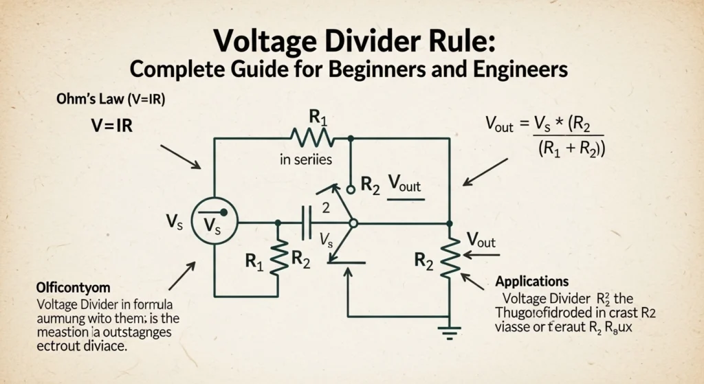
The Voltage Divider Rule is a basic electrical principle used to calculate the voltage across components connected in series.
Definition
It states that the voltage across any resistor in a series circuit is proportional to its resistance.
Simple Explanation
If you connect multiple resistors in series, the total voltage supplied gets divided among them based on their resistance values.
Mathematical Formula
V_x = V_{total} \times \frac{R_x}{R_{total}}
Where:
- ( V_x ) = Voltage across resistor
- ( V_{total} ) = Total supply voltage
- ( R_x ) = Resistance of the selected resistor
- ( R_{total} ) = Total resistance
Practical Example
If two resistors (2Ω and 4Ω) are connected in series across a 12V supply:
- Total resistance = 6Ω
- Voltage across 2Ω = 4V
- Voltage across 4Ω = 8V
3. Voltage Divider Rule Working Principle
The Voltage Divider Rule working principle is based on Ohm’s Law and series circuit behavior.
Step-by-Step Explanation
- A voltage source is applied to a series circuit
- Current flows equally through all resistors
- Each resistor drops voltage depending on its value
- Higher resistance → higher voltage drop
Easy Analogy
Think of water flowing through pipes. If one pipe is narrower (higher resistance), it restricts flow more, causing a larger pressure drop. Similarly, higher resistance causes more voltage drop.
Key Points
- Voltage divides in proportion to resistance
- Current remains constant in series circuits
- Total voltage equals sum of individual voltages
4. Types / Classification of Voltage Divider
Passive Voltage Divider
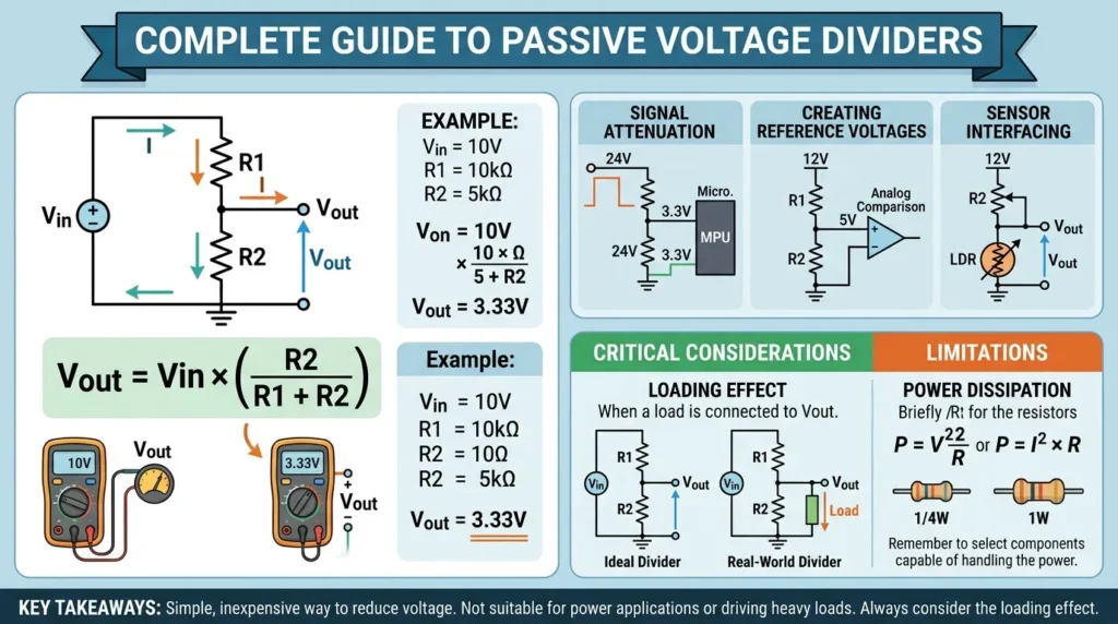
A Passive Voltage Divider is a simple electrical circuit used to reduce a higher voltage to a lower voltage using only passive components like resistors. It is one of the most basic and widely used concepts in electronics and electrical engineering. The circuit consists of two or more resistors connected in series across a voltage source, and the output voltage is taken from the junction between them. This method is commonly used in low-power electronic circuits where only a small voltage is required for sensors, control systems, or signal processing.
The working principle of a passive voltage divider is based on Ohm’s Law and the principle of voltage drop across resistors. When a voltage is applied across the series-connected resistors, the total voltage is divided between them in proportion to their resistance values. A higher resistance drops more voltage, while a lower resistance drops less voltage. For example, if two equal resistors are used, the output voltage will be half of the input voltage. This makes it easy to design circuits that need specific voltage levels without using complex components.
Passive voltage dividers are commonly used in electronic circuits, sensor interfacing, analog signal processing, and measurement systems. For example, they are used to scale down voltage levels before feeding them into microcontrollers or analog-to-digital converters (ADC), which operate at lower voltages.
One of the main advantages of a passive voltage divider is its simplicity. It is easy to design, low cost, and requires no external power source. It also uses very few components, making it reliable and compact. However, it has some limitations. It cannot supply high current because it is not designed for power delivery. The output voltage may also change if the load connected to it varies, making it unsuitable for heavy or unstable loads.
Overall, a Passive Voltage Divider is a fundamental and practical circuit used in electrical and electronic systems for voltage scaling, signal conditioning, and measurement applications where only small current is required.
Uses only resistors.
- Simple design
- No external power control
- Common in basic circuits
Loaded Voltage Divider
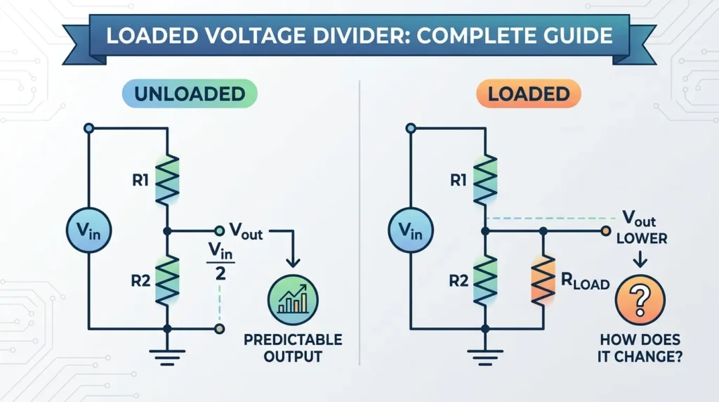
A Loaded Voltage Divider is an improved version of the basic passive voltage divider circuit in which a load resistor is connected across the output terminals. This circuit is widely used in real electronic systems where a device or load is actually connected to the output, not just an open circuit. Because of this load, the output voltage changes compared to an ideal (no-load) voltage divider, making the analysis more practical and realistic for engineering applications.
The working principle of a loaded voltage divider is based on Ohm’s Law and the concept of parallel resistance. In a simple voltage divider, two resistors are connected in series across a supply voltage, and the output is taken from the middle point. However, when a load resistor is connected at the output, it comes in parallel with the lower resistor. This parallel combination changes the total resistance of the lower part of the circuit, which directly affects the output voltage. As a result, the output voltage becomes lower than the ideal calculated value because the current now splits between the load and the resistor network.
Loaded voltage dividers are commonly used in electronic circuits where real devices are connected, such as sensor circuits, signal conditioning systems, control circuits, and analog measurement systems. For example, when a microcontroller reads voltage from a sensor through a divider, the input pin acts as a load, affecting the output voltage.
One of the main advantages of a loaded voltage divider is that it represents real-world conditions more accurately than an ideal divider. It helps engineers design circuits that behave correctly under actual operating loads. However, it also has limitations. The output voltage is not stable and changes depending on the load resistance. If the load varies, the voltage becomes unpredictable, which can cause errors in sensitive circuits.
Overall, a Loaded Voltage Divider is an important practical circuit used in electrical and electronic engineering to understand real voltage behavior when a load is connected, helping in better design of measurement and control systems.
When a load is connected to the output.
- Output voltage changes
- Accuracy reduces
- Used in real circuits
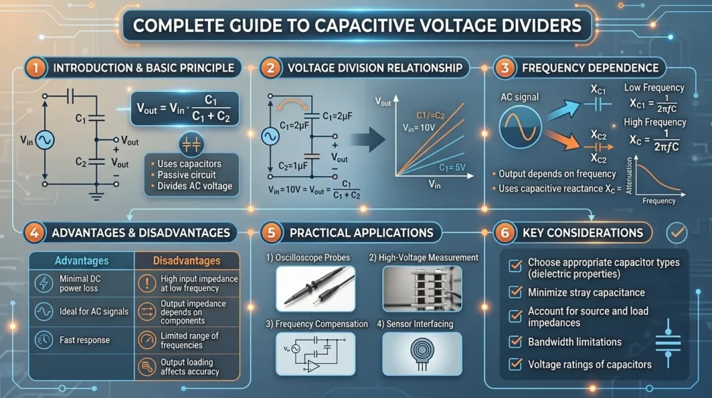
Capacitive Voltage Divider
A Loaded Voltage Divider is an improved version of the basic passive voltage divider circuit in which a load resistor is connected across the output terminals. This circuit is widely used in real electronic systems where a device or load is actually connected to the output, not just an open circuit. Because of this load, the output voltage changes compared to an ideal (no-load) voltage divider, making the analysis more practical and realistic for engineering applications.
The working principle of a loaded voltage divider is based on Ohm’s Law and the concept of parallel resistance. In a simple voltage divider, two resistors are connected in series across a supply voltage, and the output is taken from the middle point. However, when a load resistor is connected at the output, it comes in parallel with the lower resistor. This parallel combination changes the total resistance of the lower part of the circuit, which directly affects the output voltage. As a result, the output voltage becomes lower than the ideal calculated value because the current now splits between the load and the resistor network.
Loaded voltage dividers are commonly used in electronic circuits where real devices are connected, such as sensor circuits, signal conditioning systems, control circuits, and analog measurement systems. For example, when a microcontroller reads voltage from a sensor through a divider, the input pin acts as a load, affecting the output voltage.
One of the main advantages of a loaded voltage divider is that it represents real-world conditions more accurately than an ideal divider. It helps engineers design circuits that behave correctly under actual operating loads. However, it also has limitations. The output voltage is not stable and changes depending on the load resistance. If the load varies, the voltage becomes unpredictable, which can cause errors in sensitive circuits.
Overall, a Loaded Voltage Divider is an important practical circuit used in electrical and electronic engineering to understand real voltage behavior when a load is connected, helping in better design of measurement and control systems.
Uses capacitors instead of resistors.
- Used in AC circuits
- Frequency-dependent
- Common in signal processing
Inductive Voltage Divider
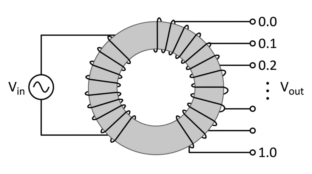
An Inductive Voltage Divider is an electrical device used to divide voltage using inductors instead of resistors. It works on the principle of inductive reactance, where voltage is distributed across coils based on their inductance values. This type of voltage divider is mainly used in AC circuits, especially where high accuracy and stability are required. It is commonly found in power systems, laboratory measurements, and calibration equipment.
The working principle of an inductive voltage divider is based on the fact that inductors oppose changes in alternating current due to their reactance. When an AC voltage is applied across a coil or a series of coils, the voltage drop across each section depends on its inductive reactance. By designing coils with precise inductance values, the input voltage can be divided into smaller, accurate output voltages. Unlike resistive dividers, inductive voltage dividers do not waste much power as heat, making them more efficient for AC applications. The output voltage ratio is controlled by selecting different tap points on the inductor winding.
Inductive voltage dividers are widely used in electrical measurement systems, high-precision laboratory instruments, calibration setups, and power system testing. They are especially useful in situations where accurate AC voltage scaling is required without introducing significant errors or power loss. For example, in testing laboratories, they help in measuring high voltages safely by scaling them down to measurable levels.
One of the main advantages of an inductive voltage divider is its high accuracy and stability in AC circuits. It provides low power loss and better performance compared to resistive dividers at higher frequencies. However, it also has some limitations. It is not suitable for DC circuits and is more expensive and complex to design. It also requires careful construction to maintain accuracy, as small variations in winding can affect performance.
Overall, an Inductive Voltage Divider is an important precision tool in electrical engineering, used for accurate AC voltage measurement and calibration in professional and industrial environments.
Uses inductors.
- Rarely used
- Applied in special AC systems
5. Main Components
1. Voltage Source
Provides input voltage.
2. Resistors
Divide voltage based on resistance values.
3. Connecting Wires
Provide path for current flow.
4. Load (Optional)
Device connected to output (e.g., sensor, LED).
Function Summary
- Source supplies energy
- Resistors control voltage division
- Load uses output voltage
6. Advantages of Voltage Divider Rule
- Simple and easy to understand
- Requires low cost components
- Widely used in circuit design
- Helps in voltage scaling
- Useful for sensor interfacing
- No complex equipment needed
7. Disadvantages / Limitations
- Not efficient for high power circuits
- Output voltage changes with load
- Energy loss as heat
- Limited accuracy in practical use
- Not suitable for variable loads
8. Voltage Divider Applications
The Voltage Divider applications are found everywhere in electrical and electronic systems.
Home Applications
- LED brightness control
- Fan speed regulators
- Voltage reduction circuits
Industrial Applications
- Sensor signal conditioning
- Control circuits
- Measurement systems
Modern Technology
- Microcontroller input circuits
- Audio volume control
- Battery voltage monitoring
9. Comparison Section
Difference Between Voltage Divider and Current Divider
| Feature | Voltage Divider | Current Divider |
|---|---|---|
| Circuit Type | Series | Parallel |
| Function | Divides voltage | Divides current |
| Formula Basis | Resistance | Conductance |
| Application | Voltage control | Current sharing |
| Complexity | Simple | Moderate |
10. Selection Guide
Choosing the right voltage divider depends on application.
Tips for Beginners
- Use accurate resistor values
- Avoid very high resistance (noise issues)
- Avoid very low resistance (power loss)
- Consider load effect
- Use buffer circuits if needed
Practical Advice
Always calculate power rating of resistors to avoid overheating.
11. Common Problems & Solutions
Q1: Why is output voltage lower than expected?
Because of load effect. The connected device draws current.
Solution: Use buffer amplifier.
Q2: Why resistors heat up?
Due to power loss.
Solution: Use higher wattage resistors.
Q3: Can voltage divider work with AC?
Yes, using capacitive or inductive dividers.
Q4: How to improve accuracy?
- Use precision resistors
- Minimize load effect
12. Future Trends
Modern electronics is improving voltage divider usage.
New Developments
- Digital voltage scaling
- Smart sensors with built-in dividers
- Low-power circuit design
- Integrated voltage divider ICs
These advancements are making circuits more efficient and compact.
13. Conclusion
The Voltage Divider Rule is one of the most fundamental concepts in electrical engineering. It allows you to divide voltage easily using simple resistor networks. From small electronic devices to complex industrial systems, this principle is widely used.
Understanding the Voltage Divider Rule working principle helps you design circuits efficiently and predict voltage behavior accurately. While it has some limitations, especially with load effects and power loss, proper design techniques can overcome these challenges.
For beginners, mastering this concept builds a strong foundation in circuit analysis. As you progress, you will find the Voltage Divider applications everywhere in real-world systems. Keep practicing calculations and experimenting with circuits to gain confidence and expertise.