
Imagine an electrical circuit containing several resistors, voltage sources, and branches. You need to calculate the current flowing through each part, but the circuit has many interconnected paths. Looking at the entire circuit at once can become confusing. This is where the concept of a mesh becomes useful.
In electrical engineering, a mesh is a closed path in a circuit that does not contain another closed path inside it. Mesh analysis provides a systematic way to calculate unknown currents and voltages in complex circuits. It is especially useful when a circuit contains multiple loops and several components connected together.
Understanding Mesh Meaning is important for electrical students because mesh analysis is a basic circuit-analysis technique. Engineers and technicians can also use the concept when studying DC circuits, AC circuits, control circuits, and electronic networks.
In this article, you will learn what a mesh is, how mesh analysis works, different types of meshes, important circuit components, advantages and limitations, applications, the difference between a mesh and a loop, practical troubleshooting, and future developments in circuit-analysis technology.
What Is Mesh?
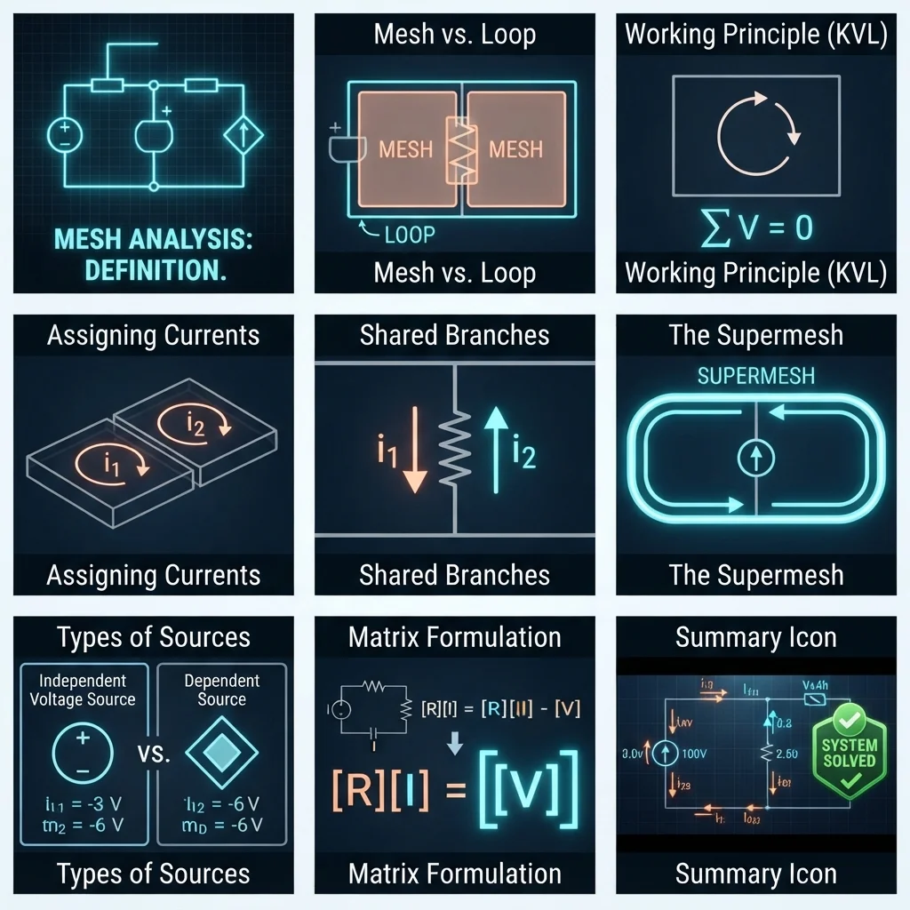
In electrical circuit theory, a mesh is a closed path in a planar circuit that contains no other closed path within it.
In simple words, a mesh is the smallest closed area or loop in a circuit.
For example, imagine a circuit shaped like a rectangle with a resistor and voltage source around its edges. The closed rectangular path can form one mesh.
If another branch divides the rectangle into two smaller sections, the original large loop may contain two smaller meshes.
Simple Definition
A mesh is a closed path in a circuit that does not contain another closed path inside it.
This definition is important because not every loop is necessarily a mesh.
Practical Example
Suppose a circuit has two adjacent rectangular sections separated by a resistor.
You can identify:
- Mesh 1 — left section
- Mesh 2 — right section
Each section is a separate mesh.
The branch shared by both sections carries current that depends on both mesh currents.
This is the basic idea behind mesh analysis.
Mesh Current
A mesh current is an assumed current assigned to each mesh.
The direction can usually be selected arbitrarily, often clockwise for convenience.
If the final calculated current is negative, it simply means the actual current flows opposite to the assumed direction.
Mesh Working Principle
The mesh working principle is based on Kirchhoff’s Voltage Law (KVL).
KVL states that the algebraic sum of all voltage rises and voltage drops around a closed path is zero.
In mesh analysis, engineers assign an unknown current to each mesh and then write a KVL equation for each independent mesh.
Step-by-Step Process
1. Identify the Meshes
Look at the circuit and identify every smallest closed area.
2. Assign Mesh Currents
Assign a current to each mesh.
A common approach is to assume all mesh currents flow clockwise.
For example:
- I₁ = current in Mesh 1
- I₂ = current in Mesh 2
- I₃ = current in Mesh 3
3. Apply Kirchhoff’s Voltage Law
Write a voltage equation around each mesh.
The total voltage rise and voltage drop around the mesh must balance.
4. Handle Shared Components
If a resistor is shared between two meshes, its current is based on the difference between the two mesh currents.
For example:
Resistor current = I₁ − I₂
The exact sign depends on the selected current directions.
5. Solve the Equations
The resulting equations can be solved using:
- Algebra
- Substitution
- Elimination
- Matrix methods
- Circuit-analysis software
Easy Water Analogy
Imagine several small water loops connected together.
You want to know how much water circulates in each loop.
Instead of analyzing every pipe separately, you assign a flow to each loop and then determine how the shared pipes behave.
Mesh analysis uses a similar idea for electrical current.
Basic Mesh Analysis Example
Consider a simple two-mesh circuit.
Suppose:
- Mesh 1 contains a 10 V source and a 4 Ω resistor.
- Mesh 2 contains a 5 V source and a 6 Ω resistor.
- Both meshes share a 2 Ω resistor.
Assign clockwise currents:
I₁ for Mesh 1
I₂ for Mesh 2
The shared resistor current depends on the difference between the mesh currents.
For Mesh 1, a simplified KVL equation could be written as:
10 − 4I₁ − 2(I₁ − I₂) = 0
For Mesh 2, another equation can be developed according to the source polarity and assumed current directions.
The two equations can then be solved simultaneously.
The important lesson for beginners is not to memorize one equation. Instead, understand the process:
Identify meshes → assign currents → apply KVL → handle shared branches → solve equations.
Types / Classification of Meshes
Meshes can be classified according to circuit structure and analysis requirements.
1. Simple Mesh
A simple mesh contains one closed path with no internal branch creating another closed path.
It is the easiest type to analyze.
For example, a basic resistor connected to a voltage source in a single closed circuit can form one mesh.
2. Multiple-Mesh Circuit
A multiple-mesh circuit contains two or more meshes.
Each mesh receives its own assumed mesh current.
For example:
- Mesh 1 → I₁
- Mesh 2 → I₂
- Mesh 3 → I₃
This arrangement is common in circuit-analysis problems.
3. Shared-Branch Mesh
Two adjacent meshes may share one or more components.
A resistor between two meshes is a common example.
The branch current depends on the relationship between the corresponding mesh currents.
If both currents are assumed clockwise, the shared resistor may have a current of:
I₁ − I₂
from the perspective of Mesh 1.
4. Independent Mesh
An independent mesh provides a unique KVL equation that is not simply a combination of other mesh equations.
Independent meshes are important when determining the minimum number of equations needed for analysis.
5. DC Mesh
Mesh analysis can be applied to DC circuits containing:
- Batteries
- DC voltage sources
- Resistors
- DC current sources
The equations are generally straightforward because frequency-dependent components are not involved in a basic resistive DC circuit.
6. AC Mesh
Mesh analysis can also be applied to AC circuits.
In AC analysis, resistors may be combined with:
- Inductors
- Capacitors
- AC voltage sources
Impedance is used instead of simple resistance where appropriate.
For example:
Z = R + jX
The same general KVL approach is used, but the quantities may be complex numbers.
Main Components Related to Mesh Analysis
A mesh is a circuit concept rather than a physical component. However, several electrical components are commonly involved in mesh analysis.
Resistor
A resistor opposes current flow and creates a voltage drop.
Ohm’s law gives:
V = IR
Resistors are very common in mesh-analysis problems.
Voltage Source
A voltage source provides electrical potential difference.
Examples include:
- Batteries
- DC power supplies
- AC sources
- Generator equivalents
The source voltage is included in the KVL equation.
Current Source
A current source attempts to maintain a specified current.
Current sources require special treatment in mesh analysis, particularly when a current source is shared by two meshes.
Inductor
An inductor stores energy in a magnetic field.
In AC mesh analysis, its impedance is:
ZL = jωL
where:
- ω = angular frequency
- L = inductance
Capacitor
A capacitor stores energy in an electric field.
Its AC impedance is:
ZC = 1 / jωC
where:
- C = capacitance
Conductors
Wires provide electrical connections between components.
Their resistance may be small, but practical circuit analysis should consider conductor effects when they are significant.
Switches
Switches can open or close branches and change the circuit topology.
The mesh structure may therefore change when a switch changes state.
Advantages of Mesh Analysis
Mesh analysis offers several practical benefits.
- Provides a systematic method for solving complex planar circuits.
- Reduces the number of unknowns in many circuits.
- Works well with voltage-source circuits.
- Makes KVL application easier by focusing on independent meshes.
- Helps calculate branch currents after mesh currents are known.
- Can be applied to DC and AC circuits.
- Works well with circuit simulation and engineering software.
- Improves understanding of circuit relationships for electrical students.
- Can simplify large resistor networks compared with writing equations for every branch current.
For many planar circuits, mesh analysis is faster and more organized than analyzing every branch separately.
Disadvantages / Limitations
Mesh analysis is useful, but it is not the best method for every circuit.
Mainly Used for Planar Circuits
Traditional mesh analysis is most convenient for planar circuits.
A non-planar circuit may require another analysis method.
Can Become Complex
Circuits with many meshes can produce many simultaneous equations.
Current Sources Require Special Treatment
A current source between two meshes may require the creation of a supermesh.
Manual Calculation Can Take Time
Large circuits may require matrix calculations or software.
Less Convenient for Some Circuits
Nodal analysis may be simpler when a circuit contains many current sources and fewer essential nodes.
Sign Errors Are Common
Beginners often make mistakes with:
- Voltage polarity
- Current direction
- Shared resistor currents
- Source signs
Careful labeling is essential.
Mesh Applications
The mesh applications extend across electrical engineering and electronics.
Electrical Education
Mesh analysis is widely taught in:
- Circuit theory
- Electrical engineering courses
- Electronics courses
- Engineering laboratories
It helps students understand KVL and current relationships.
Electronic Circuits
Engineers can use mesh analysis for circuits containing:
- Resistors
- Capacitors
- Inductors
- Voltage sources
- Amplifier networks
Power Systems
Simplified circuit models can use loop-based analysis to study electrical networks.
More advanced power-system methods may use other mathematical techniques, but the underlying circuit principles remain important.
Control Systems
Electrical control circuits can contain multiple interconnected paths.
Mesh concepts help engineers understand current and voltage relationships in these networks.
Industrial Equipment
Mesh analysis can help technicians and engineers understand:
- Control circuits
- Relay networks
- Motor-control circuits
- Power supplies
- Electronic control boards
Modern Technology
Circuit-analysis principles are also used when designing:
- Electric vehicles
- Battery systems
- Solar inverters
- Robotics
- Automation equipment
- Consumer electronics
- Communication devices
Computer-based circuit simulators often solve systems of equations that are based on the same fundamental electrical laws.
Difference Between Mesh and Loop
The difference between mesh and loop is an important topic for beginners.
A loop is any closed path in a circuit.
A mesh is a closed path that contains no other closed path inside it.
Therefore:
Every mesh is a loop, but not every loop is a mesh.
| Feature | Mesh | Loop |
|---|---|---|
| Definition | Smallest closed path without another loop inside | Any closed path |
| Internal closed path | None | May contain another loop |
| Use in analysis | Commonly used for mesh analysis | General circuit concept |
| Circuit type | Mainly planar circuits | Can describe many circuit paths |
| Example | One small section of a multi-loop circuit | Outer path surrounding multiple meshes |
Simple Example
Imagine two squares connected side by side.
Each square can be a mesh.
The outer boundary around both squares is a loop, but it is not an individual mesh because it contains smaller closed paths.
Difference Between Mesh Analysis and Nodal Analysis
Mesh analysis and nodal analysis are two major circuit-analysis methods.
| Feature | Mesh Analysis | Nodal Analysis |
|---|---|---|
| Main law | KVL | KCL |
| Main unknown | Mesh current | Node voltage |
| Best suited | Many voltage sources | Many current sources |
| Circuit requirement | Mainly planar circuits | More broadly applicable |
| Equations | Mesh equations | Node equations |
| Shared elements | Important for resistor currents | Important for node connections |
Which One Should You Use?
A useful beginner rule is:
Many voltage sources → consider mesh analysis.
Many current sources → consider nodal analysis.
This is not an absolute rule. The best method depends on the circuit structure.
Selection Guide
When deciding whether to use mesh analysis, examine the circuit before writing equations.
Step 1: Check the Circuit Shape
Determine whether the circuit is planar.
Step 2: Count the Meshes
Identify the smallest closed areas.
Step 3: Look for Voltage Sources
Mesh analysis is often convenient when voltage sources are prominent.
Step 4: Check Current Sources
If current sources are present between meshes, you may need a supermesh.
Step 5: Assign Directions
Choose a consistent direction for each mesh current.
Clockwise is often convenient.
Step 6: Label Polarities
Mark voltage rises and drops carefully.
Step 7: Write KVL Equations
Go around each independent mesh systematically.
Beginner Tip
Do not rush directly into calculations.
First draw the circuit clearly, label every mesh current, identify shared components, and mark source polarities.
Most beginner errors occur before the mathematical calculation even begins.
Common Problems & Solutions
What is a mesh in electrical engineering?
A mesh is a closed path in a planar circuit that contains no other closed path inside it.
Is every loop a mesh?
No.
A mesh is a specific type of loop. It must not contain another closed path within it.
What law is used in mesh analysis?
Mesh analysis primarily uses Kirchhoff’s Voltage Law (KVL).
Why do mesh currents have arbitrary directions?
The direction is an assumed reference.
If the calculated current is negative, the actual current flows opposite to the assumed direction.
What happens when two meshes share a resistor?
The current through the shared resistor is related to the difference between the two mesh currents, depending on the chosen directions.
For example:
Ishared = I₁ − I₂
What is a supermesh?
A supermesh is used when a current source lies on a branch shared by two meshes.
Instead of writing KVL directly through the current source, the surrounding outer path is considered, along with an additional current constraint.
Can mesh analysis be used for AC circuits?
Yes.
For AC circuits, impedance is used to represent resistors, inductors, and capacitors as appropriate.
What is the biggest mistake beginners make?
The most common errors are incorrect signs, wrong shared-resistor currents, and incorrect source polarity.
A clear circuit diagram prevents many of these mistakes.
Can software perform mesh analysis?
Yes.
Circuit-analysis software can solve the equations automatically.
However, understanding the underlying KVL and mesh-current method is still important for engineers and technicians.
Future Trends in Mesh Analysis
Circuit analysis is becoming increasingly connected with computer-based engineering tools.
Automated Circuit Solvers
Modern software can automatically create and solve circuit equations.
Engineers can analyze large networks much faster than with manual calculations.
AI-Assisted Engineering Tools
New engineering software can assist with circuit interpretation, equation generation, simulation, and fault analysis.
However, engineers still need to verify results against circuit laws and practical design requirements.
Digital Twin Technology
Digital twins can represent electrical equipment and circuits in software.
Engineers can simulate operating conditions before making physical changes to equipment.
Automated PCB Analysis
Modern PCB design software can analyze electrical networks containing thousands of interconnected components.
Electric Vehicles
EV power electronics contain complex networks involving:
- Batteries
- Inverters
- Motors
- Capacitors
- Inductors
- Switching devices
Advanced circuit-analysis techniques help engineers model and optimize these systems.
Renewable Energy Systems
Solar inverters, battery systems, and grid-connected converters require accurate circuit modeling.
Mesh and related circuit-analysis concepts remain part of the mathematical foundation behind these systems.
Conclusion
Mesh Meaning is a fundamental concept in electrical circuit analysis. A mesh is a closed path that does not contain another closed path inside it. Mesh analysis uses these paths to create systematic KVL equations and determine unknown circuit currents.
The method is especially useful for planar circuits containing multiple voltage sources and resistive or impedance-based branches. By assigning mesh currents, writing KVL equations, handling shared components correctly, and solving the resulting equations, engineers can analyze circuits efficiently.
The key point to remember is the difference between mesh and loop: every mesh is a loop, but a loop can contain other closed paths and therefore may not be a mesh.
For beginners, practice is the best way to master this topic. Start with one-mesh circuits, then move to two-mesh and three-mesh circuits. Once the process becomes familiar, more complex electrical networks become much easier to analyze.