Imagine you are standing inside a large factory. Heavy motors are running, control panels are energized, and high-power machines operate day and night. Suddenly, a fault occurs inside one machine. If there is no proper earthing system, that metal body can become live and cause serious electric shock, fire, or equipment damage.
This is why Industrial Earthing is one of the most important safety systems in any industrial installation. It protects human life, prevents equipment failure, and ensures reliable system performance.
In this detailed guide, you will learn the Industrial Earthing working principle, different types of earthing systems, components used, advantages and disadvantages, applications, comparison with other grounding systems, selection guide, troubleshooting tips, and future trends.
As a senior electrical engineer, I can confidently say: if your earthing system is strong, your electrical system is safe. Let’s understand it step by step.
2. What is Industrial Earthing?
Industrial Earthing is the process of connecting non-current-carrying metal parts of electrical equipment to the earth (ground) to ensure safety during fault conditions.
In simple words, it provides a low-resistance path for fault current to safely flow into the ground.
Practical Example
Suppose insulation inside a motor fails and the phase wire touches the metal body. Without earthing, the motor body becomes live. If a worker touches it, electric shock can occur.
With proper Industrial Earthing:
- Fault current flows directly into the earth
- Protective devices (MCB/Relay) trip quickly
- The system becomes safe
This is why Industrial Earthing is essential in factories, power plants, substations, and large commercial buildings.
3. Industrial Earthing Working Principle
The Industrial Earthing working principle is based on providing the lowest resistance path to ground for fault current.
Let’s understand step-by-step:
- Under normal conditions, current flows through phase and neutral.
- The equipment body remains non-energized.
- During a fault, phase touches metal body.
- Fault current flows through earthing conductor.
- Current reaches earth electrode.
- Protective device detects high current.
- Circuit breaker trips immediately.
Simple Analogy
Think of earthing like an emergency exit door in a building.
When everything is normal, nobody uses it. But in case of fire (fault), people use the emergency exit to escape safely.
Similarly, fault current uses the earthing path to safely escape into the ground.
4. Types / Classification of Industrial Earthing
There are different types of Industrial Earthing systems used depending on soil condition, load type, and safety requirements.
4.1 Plate Earthing
- A copper or GI plate is buried deep in the ground.
- Charcoal and salt are placed around it to reduce resistance.
- Used in large installations.
4.2 Pipe Earthing
- Most common and economical method.
- A perforated GI pipe is buried vertically.
- Suitable for industries with moderate load.
4.3 Rod Earthing
- Copper or steel rod driven deep into the soil.
- Quick installation.
- Used in rocky areas.
4.4 Strip or Wire Earthing
- Metal strip buried horizontally.
- Used in substations and transmission lines.
4.5 Grid Earthing (Mat Earthing)
- Network of conductors buried underground.
- Used in power plants and substations.
- Provides uniform ground potential.
4.6 Chemical Earthing
- Uses special chemical compounds.
- Maintains low resistance for long time.
- Ideal for dry and sandy soil.
Each type has different Industrial Earthing advantages and disadvantages depending on soil and system size.
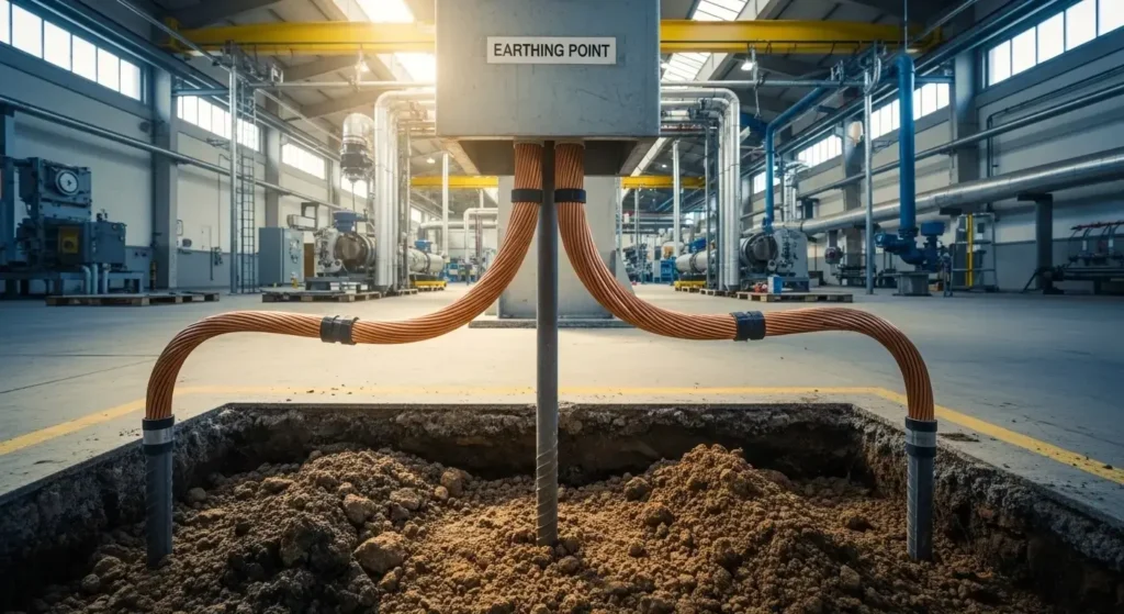
5. Main Components of Industrial Earthing System
An Industrial Earthing system consists of several important components.
5.1 Earth Electrode
Buried conductor that makes direct contact with soil.
5.2 Earthing Conductor
Connects equipment body to electrode.
5.3 Earth Pit
Location where electrode is installed.
5.4 Earth Busbar
Common connection point in control panels.
5.5 Inspection Chamber
Allows checking and testing of earth resistance.
Each component must be properly installed to ensure low resistance and long life.
6. Advantages of Industrial Earthing
Industrial Earthing advantages and disadvantages must be clearly understood. Let’s start with benefits:
- Protects human life from electric shock
- Prevents fire hazards
- Protects expensive equipment
- Improves system stability
- Ensures proper operation of relays
- Reduces electrical noise
- Complies with safety standards
In simple words, good earthing saves money and lives.
7. Disadvantages / Limitations
Even though it is essential, Industrial Earthing has some limitations:
- Installation cost can be high
- Requires regular maintenance
- Soil condition affects performance
- Corrosion can damage electrodes
- Poor design may increase resistance
If not maintained properly, the system may fail during fault.
8. Industrial Earthing Applications
Industrial Earthing applications are very wide.
Home Applications
- Large residential buildings
- Generator systems
- Solar systems
Industrial Applications
- Factories
- Manufacturing plants
- Power plants
- Substations
- Heavy machinery
Modern Technology Uses
- Data centers
- Telecom towers
- Renewable energy systems
- EV charging stations
Wherever electricity is used in large quantity, Industrial Earthing is mandatory.
9. Comparison Section
Difference Between Industrial Earthing and Residential Earthing
| Feature | Industrial Earthing | Residential Earthing |
|---|---|---|
| Load Capacity | Very High | Low to Medium |
| System Complexity | Complex | Simple |
| Safety Requirement | Critical | Moderate |
| Cost | Higher | Lower |
| Maintenance | Regular testing required | Occasional testing |
The main difference between residential earthing and industrial earthing is load capacity and safety level.
Industrial systems require stronger grounding due to high fault currents.
10. Selection Guide
Choosing the right Industrial Earthing system depends on:
- Soil resistivity
- Type of load
- Fault current level
- Safety standards
- Budget
Tips for Beginners
- Always measure soil resistance first
- Use copper electrode for better conductivity
- Keep earth resistance below recommended value
- Follow local electrical codes
- Perform periodic testing
A well-designed earthing system should have low resistance and high reliability.
11. Common Problems & Solutions (FAQs Style)
Q1: Why is earth resistance high?
Solution: Check soil moisture, add water, use chemical earthing.
Q2: Why breaker is not tripping during fault?
Solution: Inspect earthing continuity and resistance value.
Q3: Why electrode is corroded?
Solution: Use copper-bonded rods or chemical compounds.
Q4: How often should testing be done?
Answer: At least once a year in industrial systems.
Proper maintenance ensures safety and reliability.
12. Future Trends in Industrial Earthing
The future of Industrial Earthing is becoming more advanced.
- Smart grounding monitoring systems
- Online earth resistance sensors
- Improved corrosion-resistant materials
- Integration with IoT systems
- Advanced simulation software for design
Industries are moving towards automated safety systems.
With renewable energy and EV systems increasing, grounding technology will continue to improve.
13. Conclusion
Industrial Earthing is not just a safety requirement; it is the backbone of any industrial electrical system. It protects people, equipment, and infrastructure from dangerous fault currents.
We discussed the Industrial Earthing working principle, types, components, applications, advantages and disadvantages, comparison with residential systems, and troubleshooting methods.
As an engineer, always remember: never compromise on grounding design. A properly installed and maintained earthing system ensures long-term safety and performance.
Keep learning, keep testing, and always follow electrical standards. Safety in electricity begins with proper earthing.