Think about a mobile charger you use every day. The power from the wall socket is high voltage, but your phone needs low voltage to charge safely. So how does this conversion happen? The answer lies in a device called a transformer, and at the heart of its operation is the turns ratio formula.
The turns ratio formula is a simple but powerful concept used to understand how voltage and current change inside a transformer. It is essential for designing electrical systems, from small electronic devices to large power transmission networks.
For electrical students, engineers, and technicians, mastering this formula is very important. It helps in analyzing transformer behavior, ensuring safety, and improving efficiency in electrical systems.
In this article, you will learn the turns ratio formula, its working principle, types, applications, advantages and disadvantages, and practical usage. The explanation is kept simple and clear so that beginners can easily understand and professionals can refresh their knowledge.
2. What is Turns Ratio Formula?
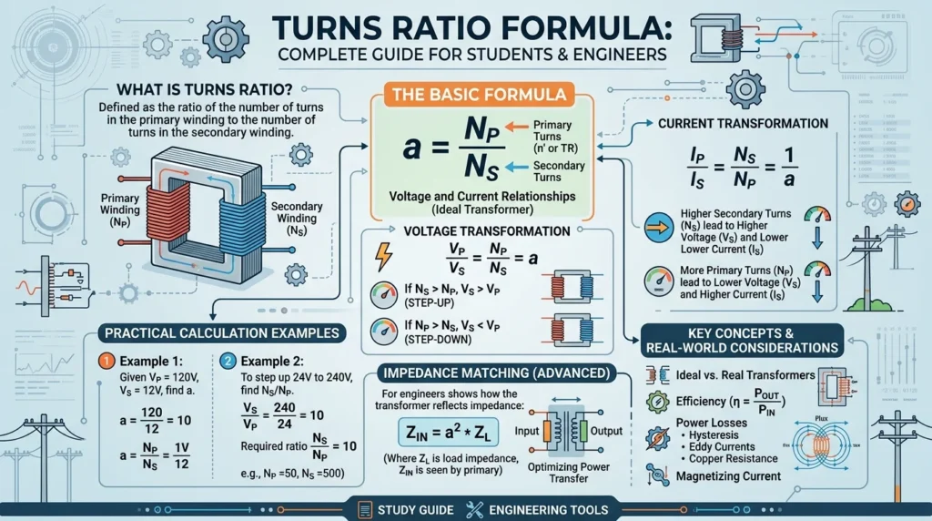
The turns ratio formula defines the relationship between the number of turns in the primary coil and the secondary coil of a transformer.
\frac{N_1}{N_2} = \frac{V_1}{V_2}
Where:
- N₁ = Number of turns in primary winding
- N₂ = Number of turns in secondary winding
- V₁ = Primary voltage
- V₂ = Secondary voltage
Simple Explanation
The formula shows that voltage is directly proportional to the number of turns in a coil. If the number of turns increases, the voltage also increases, and vice versa.
Practical Example
If:
- Primary turns (N₁) = 100
- Secondary turns (N₂) = 50
- Primary voltage (V₁) = 220V
Then:
- Secondary voltage (V₂) = 110V
This means the transformer reduces voltage, so it is a step-down transformer.
3. Turns Ratio Formula Working Principle
The turns ratio formula working principle is based on electromagnetic induction.
Step-by-Step Explanation
- AC Supply is Applied
- Alternating current flows through the primary coil.
- Magnetic Field is Generated
- The current creates a changing magnetic field in the core.
- Magnetic Flux Links Secondary Coil
- The magnetic field passes through the secondary winding.
- Voltage is Induced
- A voltage is generated in the secondary coil.
- Turns Ratio Determines Output
- The number of turns controls how much voltage is increased or decreased.
Simple Analogy
Think of a transformer like gears in a bicycle:
- More turns = bigger gear = higher output
- Fewer turns = smaller gear = lower output
4. Types / Classification
4.1 Step-Up Transformer
- Secondary turns > Primary turns
- Output voltage increases
- Used in power transmission
4.2 Step-Down Transformer
- Secondary turns < Primary turns
- Output voltage decreases
- Used in chargers and home appliances
4.3 Isolation Transformer
- Primary turns = Secondary turns
- Voltage remains the same
- Used for safety and isolation
5. Main Components
5.1 Primary Winding
- Receives input voltage
- Generates magnetic field
5.2 Secondary Winding
- Produces output voltage
- Delivers power to load
5.3 Magnetic Core
- Provides path for magnetic flux
- Improves efficiency
5.4 Insulation
- Prevents short circuits
- Ensures safety
6. Advantages
The turns ratio formula advantages and disadvantages help in practical understanding.
Advantages
- Simple and easy to calculate
- Helps design transformers accurately
- Essential for voltage control
- Improves system efficiency
- Useful in both small and large systems
- Supports safe electrical operation
7. Disadvantages / Limitations
Limitations
- Works best under ideal conditions
- Does not consider losses (heat, leakage)
- Only applicable to AC circuits
- Requires accurate turn count
- Cannot directly calculate power losses
8. Applications
The turns ratio formula applications are widely used in electrical systems.
Home Applications
- Mobile chargers
- TV power supplies
- UPS systems
Industrial Applications
- Power transformers
- Motor control systems
- Distribution networks
Modern Technology
- Renewable energy systems
- Electric vehicles
- Smart grids
9. Comparison Section
Difference Between Turns Ratio and Voltage Ratio
| Feature | Turns Ratio | Voltage Ratio |
|---|---|---|
| Definition | Ratio of coil turns | Ratio of voltages |
| Formula | N₁ / N₂ | V₁ / V₂ |
| Relationship | Directly proportional | Directly proportional |
| Use | Transformer design | Circuit analysis |
| Dependency | Physical winding | Electrical output |
10. Selection Guide
Choosing the right transformer depends on turns ratio.
Tips for Beginners
- Identify required output voltage
- Choose proper turns ratio
- Consider load requirements
- Check insulation and safety
Practical Tips
- Always verify input voltage
- Use standard transformer ratings
- Avoid overloading
- Ensure proper cooling
11. Common Problems & Solutions
Q1: Why is output voltage lower than expected?
Cause:
- Losses in transformer
- Incorrect turns ratio
Solution:
- Check winding turns
- Reduce load
Q2: Why is transformer overheating?
Cause:
- Overload
- Poor design
Solution:
- Use correct rating
- Improve cooling
Q3: Why is voltage fluctuating?
Cause:
- Input variation
- Loose connections
Solution:
- Stabilize input
- Tighten connections
Q4: Why is there no output?
Cause:
- Open circuit
- Coil damage
Solution:
- Check continuity
- Repair or replace winding
12. Future Trends
The use of the turns ratio formula is evolving with technology.
Smart Transformers
- Automated voltage control
- Real-time monitoring
Renewable Energy
- Solar and wind systems need efficient transformers
Electric Vehicles
- Voltage conversion is critical
Digital Design Tools
- Simulation software improves accuracy
13. Conclusion
The turns ratio formula is a key concept in understanding how transformers work. It explains the relationship between voltage and the number of turns in a coil, making it essential for electrical design and analysis.
From basic chargers to large power systems, this formula plays a vital role in ensuring safe and efficient energy transfer. While it has some limitations, it remains one of the most important tools for electrical engineers and technicians.
By understanding its working principle, types, and applications, you can confidently work with transformers and improve your practical knowledge. Keep practicing and applying this concept in real-world scenarios to strengthen your skills.