Imagine entering a factory where hundreds of machines operate smoothly and efficiently. Motors start exactly when needed, lighting systems function properly, and safety devices respond instantly during abnormal conditions. Behind this seamless operation is one of the most important parts of any electrical system—the electrical panel.
Electrical panel design is the process of planning and designing an electrical panel or distribution board so that it operates safely, efficiently, and reliably. The primary function of an electrical panel is to distribute electrical power to various loads, such as lights, motors, machines, and control systems, while also providing protection against short circuits, overloads, and other electrical faults. A well-designed panel ensures uninterrupted operation and protects both equipment and personnel from potential hazards.
The design process begins with load calculation, which involves determining how much current each connected load will consume and calculating the total capacity required for the system. Accurate load estimation helps engineers select the correct ratings for cables, protective devices, and other panel components. Proper calculations also prevent overloading and improve the overall efficiency of the electrical installation.
Selecting the right components is another critical aspect of electrical panel design. Components such as MCBs (Miniature Circuit Breakers), MCCBs (Molded Case Circuit Breakers), fuses, busbars, relays, timers, contactors, and meters must be chosen carefully based on their ratings, application requirements, and operating conditions. Their arrangement inside the panel should allow easy operation, safe access, and convenient maintenance. Factors such as phase separation, cable routing, and adequate spacing are also considered to ensure proper heat dissipation and reduce the risk of faults.
The panel enclosure is equally important and must be selected according to the environment in which the panel will be installed. The enclosure should provide protection against dust, moisture, corrosion, and accidental contact. In many applications, the required IP (Ingress Protection) rating is specified to ensure the panel can withstand environmental conditions safely and effectively.
Safety remains one of the most important objectives of electrical panel design. Proper earthing, insulation, ventilation, and fault protection must be incorporated to minimize the risk of electric shock, overheating, and fire hazards. Components should be arranged to allow sufficient airflow and prevent excessive heat buildup during operation. Following recognized electrical standards and safety practices ensures reliable and secure system performance.
Modern electrical panels often integrate automation and control technologies, including PLCs (Programmable Logic Controllers), sensors, timers, Human-Machine Interfaces (HMIs), and monitoring systems. These advanced features improve operational efficiency, simplify control, and enable real-time monitoring of electrical processes. As industries move toward automation and smart manufacturing, intelligent panel designs have become increasingly important.
A well-designed electrical panel not only improves safety and reliability but also enhances energy efficiency, reduces downtime, and simplifies maintenance procedures. For electrical students, technicians, and junior engineers, understanding the principles of electrical panel design is essential because panels are used in residential buildings, commercial facilities, industrial plants, and automation systems. Whether you work in basic electrical installations or advanced industrial environments, mastering electrical panel design is a valuable skill.
In this article, you will learn what electrical panel design really means, how it works, the different types of electrical panels, their main components and functions, advantages and disadvantages, practical applications, selection guidelines, troubleshooting methods, and future trends shaping the electrical industry.
Let’s start from the basics and build your understanding step by step.
2. Electrical Panel Design with diagram?
Electrical Panel Design is the process of planning, arranging, selecting, and assembling electrical components inside a control cabinet or enclosure to safely distribute and control electrical power.
In simple words, it is the “brain and heart” of an electrical system.Electrical Panel Design is a critical part of any electrical system, as it ensures safe distribution, control, and protection of electrical power in homes, commercial buildings, and industries. An electrical panel, also known as a distribution board or control panel, is the central point where incoming power is divided into different circuits and supplied to various loads such as lighting, motors, and appliances.
The design of an electrical panel starts with understanding the load requirements. Engineers calculate the total connected load, demand factor, and future expansion needs. Based on this, they select the appropriate panel size, busbar rating, and protective devices. The main incoming supply is connected to a main switch or circuit breaker, which controls the entire system. From there, power is distributed through busbars to individual outgoing circuits, each protected by devices like MCBs (Miniature Circuit Breakers), MCCBs (Molded Case Circuit Breakers), or fuses.
A key principle in electrical panel design is safety. Proper earthing (grounding) must be provided to prevent electric shocks and equipment damage. The panel should also include protective devices such as overload relays, short-circuit protection, and surge protection to handle abnormal conditions. Clear labeling of circuits and proper arrangement of components make operation and maintenance easier.
Another important aspect is the physical layout of the panel. Components should be arranged neatly with adequate spacing to allow heat dissipation and easy access for maintenance. Wires should be properly routed using cable ducts and secured with ties to avoid confusion and hazards. Ventilation or cooling systems may be added in larger panels to prevent overheating.
Electrical panel design also considers standards and regulations. Panels must comply with local and international standards such as IEC or NEC to ensure reliability and safety. Proper insulation, enclosure type (such as IP rating), and material selection are also important factors.
In modern systems, electrical panels may include automation components like PLCs (Programmable Logic Controllers), meters, and digital monitoring systems. These features improve control, efficiency, and fault detection.
Overall, a well-designed electrical panel ensures efficient power distribution, enhances safety, and reduces downtime. It is a combination of proper planning, correct component selection, and organized installation that results in a reliable electrical system.
Simple Explanation
Think of an electrical panel like a traffic control system. Electricity is like vehicles moving on roads. The panel controls:
- Where electricity goes
- How much current flows
- When to stop power
- How to protect equipment
Practical Example
In a house, the distribution board divides power into lighting, sockets, and AC circuits. In a factory, a motor control panel controls multiple motors with protection devices.
Both are results of proper electrical panel design.
3. Electrical Panel Design Working Principle
The electrical panel design working principle is based on safe power distribution, control, and protection.
Let’s understand it step by step.Electrical Panel Design – Working Principle
An electrical panel (also called a control panel or distribution board) is a system that receives electrical power from a source and safely distributes it to different circuits or equipment. It also controls, monitors, and protects electrical systems from faults such as overloads and short circuits.
⚙️ Working Principle of Electrical Panel Design
The working principle of an electrical panel is based on power distribution, control, protection, and safety. It ensures that electricity flows in a controlled and secure manner from the main supply to various loads.
1. Power Input (Incoming Supply)
The electrical panel receives power from a main source such as a transformer or generator.
- Power enters through the main incoming cable
- It first passes through a main switch or circuit breaker
👉 This allows the entire panel to be turned ON or OFF.
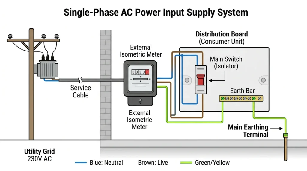
Power input, also known as incoming supply, is the electrical power that enters a building, machine, electrical panel, or system from the main power source. It is the starting point of electricity distribution and plays a vital role in ensuring that electrical equipment receives the required voltage and current for proper operation. In residential buildings, the incoming supply usually comes from the utility company’s distribution network through service lines connected to the main meter and distribution board. In industrial and commercial facilities, power input may be supplied through transformers, substations, or high-capacity electrical feeders to meet larger energy demands.
The incoming supply consists of essential electrical parameters such as voltage, current, frequency, and phase configuration. These factors must match the requirements of the electrical system to ensure safe and efficient operation. Before electricity is distributed to various circuits, it passes through protective devices such as circuit breakers, fuses, and isolators. These devices help prevent electrical faults, overloads, and short circuits from damaging equipment or causing safety hazards.
A stable power input is extremely important because fluctuations in voltage or interruptions in supply can affect the performance of electrical appliances and machinery. Sensitive equipment such as computers, medical devices, and industrial control systems often require additional protection through voltage stabilizers, surge protectors, or uninterruptible power supplies (UPS). Proper wiring, grounding, and regular maintenance of the incoming supply system are also necessary to maintain safety and reliability.
In modern electrical installations, monitoring the incoming supply helps engineers and technicians analyze power quality, energy consumption, and system efficiency. Advanced meters and monitoring devices can detect abnormalities and provide real-time information about the electrical supply. Overall, power input serves as the foundation of every electrical system, ensuring that electricity is delivered safely and effectively from the source to the connected loads. Without a reliable incoming supply, electrical systems cannot function efficiently, making it one of the most important elements of electrical power distribution.
2. Protection Mechanism
Before power is distributed, it goes through protective devices such as:
- Circuit Breakers (MCB, MCCB)
- Fuses
- Relays
👉 These devices protect the system from:
- Overload (too much current)
- Short circuit (fault condition)
- Electrical damage
If a fault occurs, the breaker automatically disconnects the circuit.
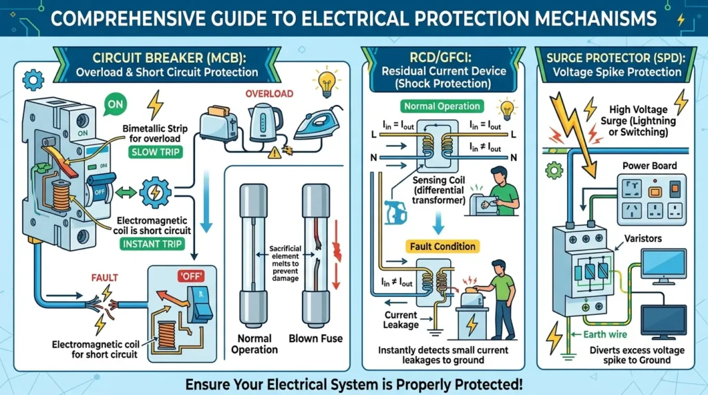
A protection mechanism is an essential part of any electrical system that helps safeguard equipment, wiring, and people from electrical faults and dangerous operating conditions. Its primary purpose is to detect abnormalities such as overloads, short circuits, earth faults, voltage surges, and leakage currents, and then take appropriate action to prevent damage. Without proper protection mechanisms, electrical systems can become unsafe, leading to equipment failure, electrical fires, costly repairs, and serious injuries.
Electrical protection mechanisms include various devices such as fuses, circuit breakers, relays, surge protectors, and residual current devices (RCDs). A fuse is one of the simplest protection devices and works by melting its internal wire when excessive current flows through it. Circuit breakers perform a similar function but can be reset after a fault is cleared. Protective relays are commonly used in industrial power systems to monitor electrical conditions and trigger circuit breakers when abnormal situations are detected. Surge protectors help shield sensitive electronic equipment from sudden voltage spikes caused by lightning strikes or switching operations.
The operation of a protection mechanism is based on continuous monitoring of electrical parameters such as current, voltage, frequency, and insulation resistance. When these values exceed safe limits, the protection device responds automatically by disconnecting the faulty section of the system. This rapid response minimizes damage and helps maintain the stability of the remaining electrical network.
Protection mechanisms are widely used in residential, commercial, and industrial installations. In homes, they protect household appliances and occupants from electrical hazards. In industries, they ensure the safe operation of expensive machinery, motors, generators, and transformers. Proper selection, installation, and maintenance of protection devices are important for ensuring reliable performance.
Modern protection systems often include digital monitoring and intelligent control features that improve accuracy and response time. These advanced systems can provide real-time fault information and support preventive maintenance. Overall, a protection mechanism is a critical safety feature that ensures electrical systems operate efficiently, reliably, and safely while reducing the risk of accidents, equipment damage, and power interruptions.
3. Power Distribution
After protection, electricity is distributed through busbars (metal strips that carry current).
- Busbars divide power into multiple outgoing circuits
- Each circuit supplies electricity to a specific load (lights, motors, machines)
👉 This ensures efficient and organized distribution of power.
4. Control System
Electrical panels may include control components such as:
- Switches
- Contactors
- Timers
- Programmable Logic Controllers (PLC)
👉 These components help in:
- Turning devices ON/OFF
- Automating operations
- Controlling machines
5. Monitoring System
Panels often include monitoring devices:
- Voltmeters
- Ammeters
- Indicator lights
👉 These help track:
- Voltage levels
- Current flow
- System status
6. Earthing (Grounding)
All panels are connected to earth for safety.
- Any leakage current flows safely to ground
- Prevents electric shock and equipment damage
🔄 Flow of Electricity in Panel
- Power enters through main supply
- Passes through main breaker
- Goes to busbars
- Distributed to different circuits
- Controlled and monitored through panel devices
- Faults are handled by protection systems
🧠 Simple Explanation
Think of an electrical panel like a traffic control system:
- Main switch = main gate
- Busbars = highways
- Circuit breakers = safety guards
- Loads = destinations
👉 It controls where and how electricity flows safely.
⚡ Advantages of Electrical Panel Design
- Safe distribution of power
- Protection against electrical faults
- Easy control and monitoring
- Organized wiring system
- Suitable for residential, commercial, and industrial use
❌ Disadvantages
- Initial installation cost can be high
- Requires proper design and maintenance
- Faulty design may cause system failure
The working principle of electrical panel design is based on receiving electrical power, protecting it from faults, and distributing it safely to different circuits. It plays a vital role in ensuring safe and efficient operation of electrical systems. A well-designed panel improves reliability, safety, and performance in any electrical installation.
Step 1: Power Input
Electricity enters the panel from:
- Utility supply
- Generator
- Transformer
This is connected to a main breaker.
Step 2: Protection
Before power goes further, it passes through protection devices such as:
- Circuit breakers
- Fuses
- Overload relays
These devices protect against:
- Overcurrent
- Short circuit
- Earth fault
Step 3: Distribution
The power is then distributed to different outgoing circuits through busbars and breakers.
Step 4: Control
Control components like:
- Contactors
- Relays
- PLCs
decide when equipment should start or stop.
Step 5: Monitoring
Meters and indicators measure:
- Voltage
- Current
- Power
- Frequency
In simple analogy, electrical panel design is like building a well-organized control room where every device has a proper place and function.
4. Types / Classification of Electrical Panels
Electrical panels can be classified based on application and function.
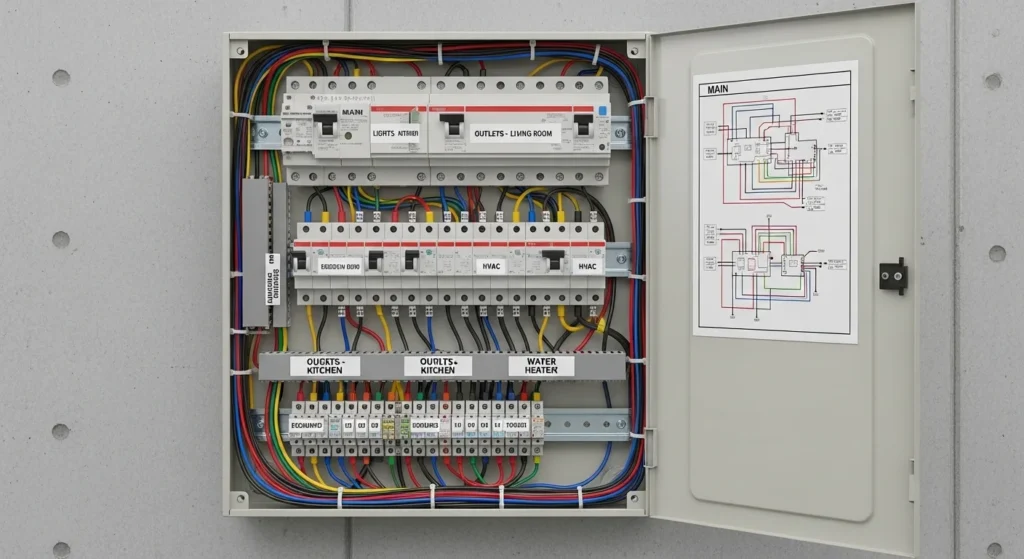
Distribution Panel (DP)
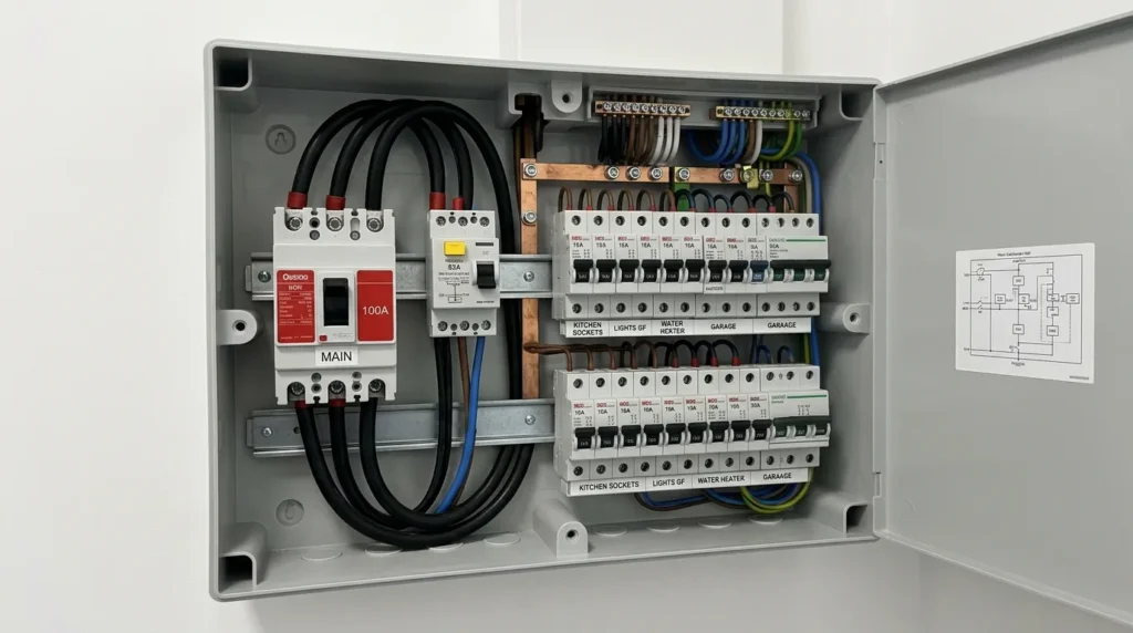
A Distribution Panel (DP) is an important electrical system used to distribute electrical power safely from the main power source to different circuits and electrical loads in homes, offices, factories, and commercial buildings. It acts as a central point where incoming electrical supply is divided into multiple outgoing circuits for lighting systems, sockets, machines, motors, and other electrical equipment. Distribution panels are essential for maintaining organized and safe electrical installations because they provide control, protection, and proper power distribution throughout the electrical network.
The main function of a distribution panel is to receive electrical power from the transformer or main supply line and distribute it to various circuits according to the load requirements. Inside the panel, several protective and control devices are installed to ensure safe operation. These include circuit breakers, fuses, bus bars, isolators, switches, meters, relays, and indicators. Circuit breakers protect circuits from overloads and short circuits by automatically disconnecting faulty lines during abnormal conditions. Bus bars are metallic strips used to distribute electrical current efficiently inside the panel.
Distribution panels are available in different types depending on voltage level and application. Common types include Main Distribution Panels (MDP), Sub Distribution Panels (SDP), Lighting Distribution Panels, and Power Distribution Panels. In industrial systems, large distribution panels may also contain monitoring systems, digital meters, and automation controls for improved efficiency and power management.
The working principle of a distribution panel is simple and effective. Electrical power enters the panel through the main incoming breaker. From there, the current is distributed through bus bars to individual circuit breakers connected to outgoing feeders. Each feeder supplies power to a specific area or electrical load. If a fault occurs in one circuit, only the affected breaker trips while the remaining circuits continue operating normally.
Distribution panels provide several advantages such as improved electrical safety, centralized control, easy maintenance, and proper load management. They also simplify fault detection and help prevent electrical accidents and fire hazards. However, distribution panels require proper installation, ventilation, and regular maintenance to ensure reliable operation.
Today, distribution panels are widely used in residential buildings, shopping malls, hospitals, industries, schools, and power systems. They are considered one of the most essential parts of modern electrical distribution systems because they ensure safe, efficient, and organized delivery of electrical power to different loads and equipment.
Used to distribute power to different circuits.
Common in homes and commercial buildings.
Motor Control Center (MCC)
A Motor Control Center (MCC) is a centralized electrical system used to control, protect, and operate multiple electric motors from a single location. MCCs are widely used in industries, factories, water treatment plants, power stations, and manufacturing units where many motors are required for pumps, conveyors, compressors, fans, and industrial machines. The main purpose of an MCC is to provide safe motor operation, simplified control, and efficient power distribution.
An MCC consists of several compartments called motor control units or feeders. Each unit contains electrical devices used for controlling and protecting a motor. The main components include contactors, circuit breakers, overload relays, fuses, push buttons, timers, control transformers, and motor starters. Modern MCCs may also include PLCs, digital meters, VFDs (Variable Frequency Drives), and automation systems for advanced motor control and monitoring.
The working principle of a Motor Control Center is based on centralized motor management. Electrical power enters the MCC through the main incoming breaker and is distributed to individual motor feeders through bus bars. Each feeder controls a specific motor. When an operator presses the start button or sends an automatic signal, the contactor energizes and supplies power to the motor. Protective devices continuously monitor current and operating conditions. If overload, short circuit, or fault conditions occur, the protective system disconnects the motor automatically to prevent damage.
Motor Control Centers are available in different types such as conventional MCCs, intelligent MCCs, and VFD-based MCCs. Intelligent MCCs use digital communication systems for remote monitoring and diagnostics, while VFD MCCs control motor speed and improve energy efficiency.
The main advantages of MCCs include centralized motor control, improved safety, easier maintenance, organized wiring, and reliable motor protection. They also reduce downtime and simplify troubleshooting in industrial systems.
Overall, Motor Control Centers are essential electrical systems that provide efficient operation, protection, and control of industrial motors in modern electrical and automation industries.
Used in industries to control multiple motors.
Includes starters, overload protection, and contactors.
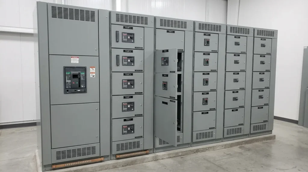
Power Control Center (PCC)
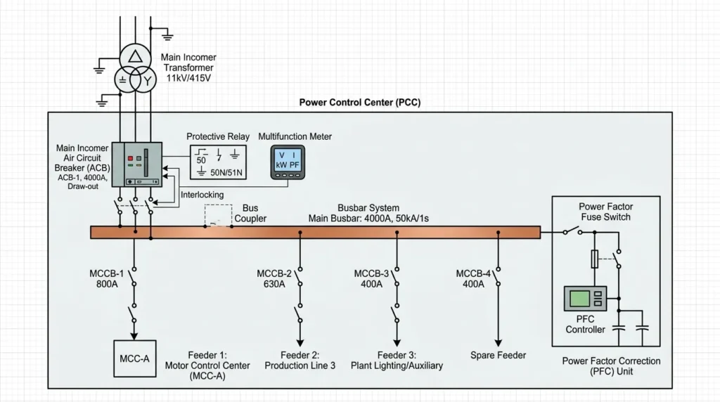
A Power Control Center (PCC) is an important electrical distribution system used to control, monitor, and distribute electrical power in industrial and commercial installations. It acts as the main point where electrical power from transformers, generators, or utility supplies is received and then distributed safely to different electrical loads, machines, and distribution panels. PCCs are widely used in factories, power plants, large buildings, hospitals, shopping malls, and industrial facilities where reliable and organized power management is required.
A PCC contains several electrical components installed inside a metal enclosure for safe operation. The main components include circuit breakers, bus bars, isolators, meters, relays, contactors, switches, protection devices, and indication systems. Circuit breakers protect the electrical system from overloads and short circuits, while bus bars distribute electrical current efficiently to outgoing feeders. Meters and indicators continuously monitor voltage, current, frequency, and power conditions.
The working principle of a Power Control Center is based on centralized power distribution and protection. Electrical power enters the PCC through the main incoming breaker and is distributed through bus bars to multiple outgoing feeders. Each feeder supplies power to a specific section or load. Protective devices monitor the system continuously and disconnect faulty circuits automatically during abnormal conditions such as overloads or short circuits. This ensures safety and reliable operation of the electrical system.
Power Control Centers are available in different types such as low-voltage PCCs and medium-voltage PCCs depending on the operating voltage level. Modern PCC systems may also include automation, digital monitoring, and energy management systems for improved efficiency and control.
The main advantages of PCCs include centralized control, better safety, organized power distribution, easy maintenance, and reliable fault protection. They also reduce downtime and improve overall system efficiency in industrial operations.
Overall, Power Control Centers are essential electrical systems that provide safe, efficient, and reliable distribution of electrical power in modern industrial and commercial applications.
Handles large power distribution in factories.
Connected directly to transformers or generators.
PLC Control Panel
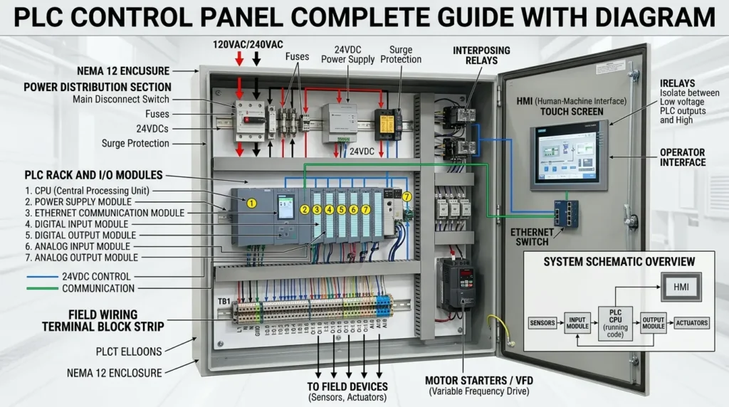
A PLC Control Panel is an advanced electrical and automation system used to control machines and industrial processes automatically with high accuracy and reliability. PLC stands for Programmable Logic Controller, which acts as the “brain” of the system. PLC control panels are widely used in industries such as manufacturing, packaging, food processing, textile, water treatment plants, and power plants where automated control is required for smooth and efficient operation.
A PLC control panel consists of several important components installed inside a metal enclosure. The main components include the PLC unit, power supply, relays, circuit breakers, contactors, terminal blocks, input/output modules (I/O modules), fuses, switches, and indicator lights. In modern systems, Human Machine Interface (HMI) screens are also added for easy monitoring and control. These components work together to manage machines and processes automatically based on programmed instructions.
The working principle of a PLC control panel is based on automation logic. First, input devices such as sensors, switches, and transmitters send signals to the PLC. The PLC processes these signals according to the programmed logic stored in its memory. After processing, it sends output signals to control devices like motors, valves, pumps, and relays. This entire process happens very quickly, allowing machines to operate smoothly without manual intervention.
PLC control panels are available in different types such as basic PLC panels, advanced automation panels, VFD integrated PLC panels, and SCADA-based systems. SCADA systems allow remote monitoring and control of industrial processes, making large-scale operations more efficient and safe.
The main advantages of PLC control panels include high accuracy, reduced human error, improved productivity, easy troubleshooting, flexible programming, and better safety. They also help in reducing operational costs and improving energy efficiency. However, PLC systems require skilled technicians for programming and maintenance, and their initial cost can be high.
Overall, PLC control panels are essential in modern automation industries because they provide intelligent control, reliable performance, and efficient management of complex industrial processes.
Used for automation systems.
Includes PLC, SMPS, relays, and communication modules.
Synchronization Panel
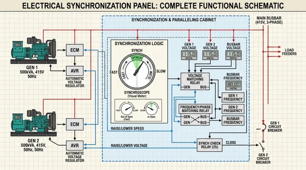
A Synchronization Panel is an important electrical control system used to match and connect two or more power sources so they can work together safely and efficiently. These power sources can include generators, transformers, or utility grids. Synchronization panels are widely used in industries, hospitals, data centers, airports, and large commercial buildings where uninterrupted power supply is essential.
The main purpose of a synchronization panel is to ensure that all power sources operate at the same electrical conditions before they are connected together. These conditions include voltage, frequency, phase sequence, and phase angle. If these parameters are not matched properly, it can cause serious damage to electrical equipment and generators.
A synchronization panel consists of several key components such as circuit breakers, synchronizing relays, synchronoscope, voltage meters, frequency meters, phase indicators, control switches, and protection devices. Modern panels may also include PLC systems and automatic synchronization modules for faster and more accurate operation.
The working principle of a synchronization panel is based on matching electrical parameters of two power sources. First, the incoming generator or source is started and its voltage and frequency are adjusted to match the running system or grid. The synchronoscope or automatic controller continuously monitors the phase difference between the sources. Once all conditions are matched, the breaker is closed, and both sources are connected in parallel to share the load safely.
Synchronization panels are available in manual and automatic types. In manual panels, an operator adjusts the parameters and connects the system, while in automatic panels, the process is controlled by intelligent electronic systems for faster and safer operation.
The main advantages of synchronization panels include uninterrupted power supply, better load sharing, improved system reliability, and efficient use of multiple generators. They also help reduce power failures in critical operations.
Overall, synchronization panels are essential electrical systems that ensure smooth and safe parallel operation of multiple power sources in modern power distribution networks.
Used when two or more generators operate together.
Each type has a specific design requirement depending on load and safety standards.
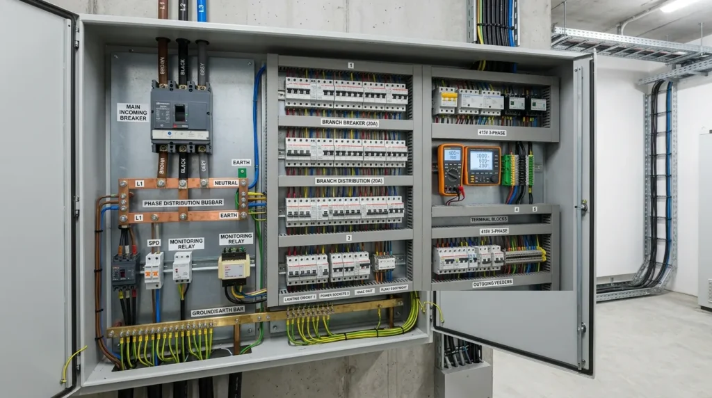
5. Main Components of Electrical Panel
Understanding the main components of an electrical panel is essential for anyone involved in electrical installation, maintenance, or panel design. Each component performs a specific function to ensure the safe distribution and control of electricity. When these components are properly selected, sized, and arranged, the panel operates efficiently and provides reliable protection. A well-designed electrical panel improves safety, simplifies troubleshooting, and extends the life of connected equipment.
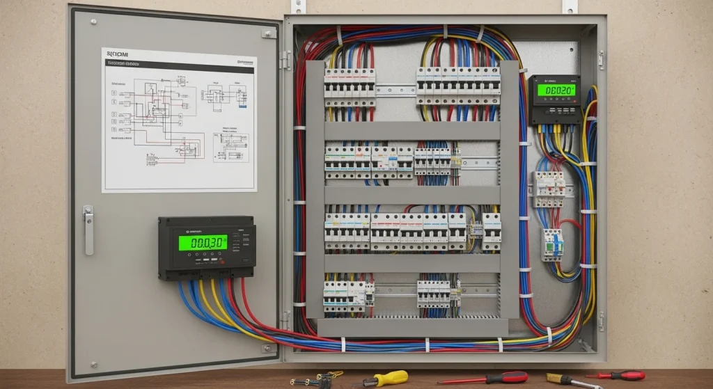
1. Enclosure
The enclosure is the outer metal cabinet that houses and protects all internal electrical components. It acts as the first line of defense against external factors such as dust, moisture, accidental contact, and physical damage. Enclosures are usually made from steel, stainless steel, or other durable materials depending on the installation environment. They are available in different sizes and protection ratings for indoor and outdoor applications. A properly designed enclosure improves safety and keeps the panel organized.
Functions of the Enclosure
- Protects internal components from damage.
- Prevents dust and moisture from entering the panel.
- Reduces the risk of accidental electric shock.
- Provides structural support for panel equipment.
- Keeps wiring and devices organized.
2. Circuit Breaker
A circuit breaker is one of the most important protective devices in an electrical panel. Its primary purpose is to interrupt the flow of electricity whenever an overload, short circuit, or fault condition occurs. It also serves as the main switching device for isolating the electrical system during maintenance or emergencies. Unlike fuses, circuit breakers can usually be reset after the fault has been corrected. This makes them practical and cost-effective for modern electrical systems.
Functions of a Circuit Breaker
- Protects against overcurrent conditions.
- Interrupts short-circuit faults automatically.
- Acts as the main switch for isolation.
- Prevents damage to electrical equipment.
- Improves the safety of the electrical system.
3. Busbars
Busbars are thick strips of copper or aluminum used to distribute electrical power within the panel. They collect incoming power and deliver it to various circuits and protective devices. Because busbars can carry large amounts of current efficiently, they reduce the need for excessive wiring inside the panel. Their arrangement also improves accessibility and simplifies maintenance. Proper sizing of busbars is critical to avoid overheating and ensure reliable operation.
Functions of Busbars
- Distribute power throughout the panel.
- Carry high electrical currents safely.
- Reduce internal wiring complexity.
- Improve efficiency and reliability.
- Simplify future modifications and maintenance.
4. Contactors
A contactor is an electrically operated switching device commonly used to control motors and other heavy electrical loads. It allows a low-power control signal to switch a high-power circuit safely. Contactors are widely used in industrial applications because they can perform frequent switching operations without damage. They often work together with overload relays to provide motor protection. Their use enhances automation and operational convenience.
Functions of Contactors
- Control motors and industrial equipment.
- Switch high-current circuits remotely.
- Enable automatic operation.
- Handle frequent switching duties.
- Improve safety in control systems.
5. Overload Relay
An overload relay protects motors from overheating caused by excessive current draw over an extended period. When a motor operates beyond its rated capacity, the relay detects the abnormal condition and disconnects the circuit before serious damage occurs. Overload relays do not protect against short circuits but are essential for preventing thermal damage to motors. They help extend motor life and reduce maintenance costs.
Functions of an Overload Relay
- Protects motors from overheating.
- Detects prolonged overcurrent conditions.
- Disconnects overloaded circuits.
- Prevents motor insulation damage.
- Increases equipment lifespan.
6. Terminal Blocks
Terminal blocks provide secure connection points between the panel’s internal wiring and external field wiring. They help organize electrical connections and make installation, inspection, and maintenance much easier. By grouping wires neatly, terminal blocks reduce wiring errors and improve troubleshooting efficiency. They are available in different sizes and configurations to suit various applications.
Functions of Terminal Blocks
- Connect field wiring to the panel.
- Organize electrical connections neatly.
- Simplify installation procedures.
- Make maintenance and testing easier.
- Reduce the chances of wiring mistakes.
7. Meters and Indicators
Meters and indicators provide important information about the operating condition of the electrical system. They display values such as voltage, current, frequency, and power consumption, allowing operators to monitor performance continuously. Indicator lights also show the status of circuits, equipment, and fault conditions. These devices help identify abnormalities quickly and support efficient operation.
Functions of Meters and Indicators
- Display voltage and current values.
- Monitor system performance.
- Indicate operating and fault conditions.
- Assist in troubleshooting.
- Improve operational awareness and safety.
Importance of Proper Component Selection
Every component inside an electrical panel must be properly sized, rated, and arranged according to the system requirements. Incorrect selection can lead to overheating, equipment failure, reduced efficiency, and safety hazards. Proper panel design ensures reliable operation, easier maintenance, and long-term performance. By understanding the function of each component, technicians and engineers can design electrical panels that are safe, efficient, and suitable for their intended applications.
6. Electrical Panel Design Advantages and Disadvantages
Advantages
- Improves electrical safety
- Prevents short circuits
- Easy fault detection
- Organized wiring system
- Better load management
- Professional and neat installation
Disadvantages / Limitations
- High initial cost
- Requires skilled design
- Needs proper maintenance
- Design errors can cause serious failures
Proper planning reduces most disadvantages.
7. Electrical Panel Design Applications
Electrical panel design applications are everywhere.
Home Use
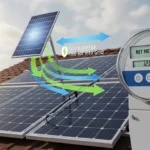
- Distribution boards
- Solar control panels
Commercial Buildings
- Lighting control panels
- HVAC control panels
Industrial Applications
- Motor control centers
- Automation panels
- Power distribution panels
Modern Technology
- Renewable energy systems
- Data centers
- Smart building systems
From small houses to large factories, electrical panels are essential.
8. Comparison Section
Let us understand the difference between control panel and distribution panel.
| Feature | Control Panel | Distribution Panel |
|---|---|---|
| Main Function | Control equipment | Distribute power |
| Used For | Motors, automation | Lighting, sockets |
| Includes | PLC, relays, contactors | Breakers, busbars |
| Complexity | High | Medium |
This comparison helps beginners understand the difference between similar systems.
9. Selection Guide
Choosing the right electrical panel design depends on:
1. Load Calculation
- Total connected load
- Future expansion
- Load calculation is the process used in electrical engineering to find the total electrical power required by a building, system, or installation. It helps engineers and technicians design safe wiring systems, select proper cables, and choose correct protective devices like circuit breakers and fuses. In simple words, it means adding the power of all electrical appliances that will be used in a place to understand the total demand. This includes lights, fans, air conditioners, motors, heaters, refrigerators, and other electrical equipment. The total load is usually measured in watts (W) or kilowatts (kW), and it is an important factor in planning any electrical system.
- Load calculation is very important because it ensures that the electrical system does not get overloaded. If the load is higher than the system capacity, it can cause overheating, short circuits, or even fire hazards. Engineers always add a safety margin, usually around 20% to 30%, to handle future expansion and unexpected load increases. This makes the system more reliable and long-lasting. Proper load calculation also improves energy efficiency and reduces power wastage.
- In residential buildings, load calculation includes basic appliances like lights, fans, televisions, and refrigerators. In commercial buildings, it includes computers, air conditioners, and office equipment. In industrial systems, heavy machines and motors are considered. Each type of load has different requirements, so accurate calculation is essential for proper system design.
- Engineers use simple formulas and methods to calculate load. For example, total load is calculated by adding the wattage of all devices. This helps in selecting the correct size of cables, transformers, and generators. If load calculation is done correctly, it ensures smooth operation of electrical systems without interruptions.
- Overall, load calculation is a fundamental step in electrical design that ensures safety, reliability, and efficiency in all types of electrical installations.
2. Voltage Level
- Single-phase or three-phase
- Voltage level refers to the amount of electrical potential difference between two points in a circuit. It is one of the most important parameters in electrical systems because it determines how electrical energy is transmitted, distributed, and used safely. Voltage is usually measured in volts (V), and different applications require different voltage levels depending on their purpose and power needs.
- In general, voltage levels are classified into categories such as low voltage, medium voltage, and high voltage. Low voltage systems, typically up to 1000V, are used in homes, offices, and small equipment. Medium voltage ranges from about 1kV to 33kV and is commonly used in industrial applications and local power distribution. High voltage, which is above 33kV, is used for long-distance power transmission because it reduces energy losses and improves efficiency.
- Maintaining the correct voltage level is essential for the safe operation of electrical devices. If the voltage is too high, it can damage equipment and create safety risks. If it is too low, devices may not work properly or efficiently. Engineers carefully design systems with proper insulation, protection devices, and voltage regulation methods to ensure stable and reliable performance. Overall, understanding voltage levels is key to building safe and efficient electrical systems.
3. Short Circuit Rating
- Fault level of supply
- Short Circuit Rating (SCR) is the maximum current that an electrical device or system can safely withstand during a fault condition without getting damaged. It is an important safety parameter used in electrical design and protection systems. When a short circuit occurs, a very high current flows instantly, which can cause overheating, fire, or equipment failure. The short circuit rating ensures that components like circuit breakers, transformers, and panels are strong enough to handle this fault current for a specific time, usually measured in kiloamperes (kA). Engineers use SCR to select proper equipment and ensure system safety, reliability, and compliance with standards.
4. Environment
- Indoor or outdoor
- Dusty or humid location
- The environment refers to everything that surrounds us, including air, water, land, plants, animals, and human-made structures. It plays a vital role in supporting life on Earth by providing essential resources such as clean air, fresh water, food, and raw materials. A healthy environment ensures the well-being of humans and other living organisms, while a polluted or damaged environment can lead to serious health problems and ecological imbalance.
- In today’s world, environmental protection has become more important than ever due to issues like pollution, climate change, and deforestation. Activities such as industrial emissions, improper waste disposal, and excessive use of natural resources are harming the environment. To reduce these effects, engineers and technicians must follow sustainable practices, such as using energy-efficient systems, minimizing waste, and adopting eco-friendly technologies.
- Protecting the environment also involves following guidelines set by organizations like United Nations Environment Programme, which promotes global environmental conservation. Simple actions like recycling, conserving energy, and reducing pollution can make a big difference.
- Overall, the environment is a shared responsibility. By protecting it, we ensure a safe, healthy, and sustainable future for the next generations.
5. Safety Standards
- Proper earthing
- Correct IP rating
- Safety standards are essential guidelines and rules designed to protect people, equipment, and the environment from accidents and hazards. In electrical and industrial fields, safety standards ensure that systems are installed, operated, and maintained in a safe and reliable manner. These standards are developed by recognized organizations such as International Electrotechnical Commission and Occupational Safety and Health Administration, which provide detailed instructions for handling electrical systems, machinery, and hazardous materials.
- Following safety standards helps reduce risks such as electric shock, fire, explosion, and equipment failure. For example, proper insulation, grounding, and use of protective devices are all part of standard safety practices. Workers are also required to use personal protective equipment (PPE) like gloves, helmets, and safety shoes to minimize injury risks.
- Safety standards also include regular inspection, testing, and maintenance of equipment to ensure everything functions correctly. In industries dealing with gases or chemicals, standards ensure proper storage, leak detection, and emergency response systems are in place.
- Overall, safety standards create a disciplined work environment where risks are controlled, and accidents are minimized. For engineers and technicians, understanding and following these standards is not optional—it is a professional responsibility that ensures safety, efficiency, and compliance in every project.
Always select components with 20–25% extra capacity for safety.
10. Common Problems and Troubleshooting Solutions in Electrical Panels
Even well-designed electrical panels can experience operational problems due to improper installation, overloading, environmental conditions, or lack of maintenance. Understanding these common issues and their solutions helps electrical students, technicians, and engineers diagnose faults quickly, improve system reliability, and maintain safe operation.
Q1: Why Does the Electrical Panel Overheat?
Panel overheating is a serious issue that can damage components, reduce equipment lifespan, and increase the risk of electrical fires.
Possible Causes:
- Loose or poorly tightened electrical connections
- Overloading beyond the panel’s rated capacity
- Inadequate ventilation inside the enclosure
- Corroded terminals and busbars
- High ambient temperatures around the panel
- Undersized conductors carrying excessive current
Recommended Solutions:
- Tighten all terminals using the manufacturer’s specified torque values.
- Verify that the connected load does not exceed the panel rating.
- Improve ventilation by installing cooling fans or adequate air circulation.
- Inspect and clean corroded connections.
- Replace undersized cables with properly rated conductors.
- Conduct periodic thermal inspections to identify hot spots before failures occur.
Q2: Why Does the Circuit Breaker Trip Frequently?
Frequent breaker tripping is an indication that the electrical system requires immediate investigation.
Possible Causes:
- Short circuits within the wiring system
- Electrical overload conditions
- Defective or aging circuit breakers
- Ground faults
- Motor starting currents exceeding breaker characteristics
- Incorrect breaker sizing
Recommended Solutions:
- Inspect wiring for damaged insulation and short circuits.
- Measure load current using a clamp meter and compare it with breaker ratings.
- Redistribute loads if the circuit is overloaded.
- Test and replace faulty breakers when necessary.
- Use breakers with appropriate trip characteristics for motor loads.
- Ensure protective devices are correctly coordinated.
Q3: Why Is There Voltage Imbalance in a Three-Phase Panel?
Voltage imbalance can negatively affect motors, transformers, and other three-phase equipment.
Possible Causes:
- Uneven distribution of single-phase loads
- Loose neutral connections
- Faulty power supply conditions
- Damaged cables or terminals
- Poor load management practices
Recommended Solutions:
- Balance electrical loads evenly across all phases.
- Inspect and tighten neutral connections.
- Measure phase voltages regularly to identify abnormalities.
- Replace damaged conductors and faulty connections.
- Monitor load variations and redistribute loads when required.
Maintaining balanced phases improves equipment efficiency and extends the service life of electrical machines.
Q4: Why Is the Wiring Inside the Panel Messy or Difficult to Maintain?
Poor wiring practices make troubleshooting more difficult and increase the likelihood of installation errors.
Possible Causes:
- Lack of planning before assembly
- Improper cable routing
- Absence of wire markers and identification labels
- Inadequate use of cable ducts and accessories
- Unorganized modifications after installation
Recommended Solutions:
- Prepare a detailed wiring layout before installation.
- Use cable ducts, trunking, and wire management accessories.
- Label all conductors and terminal points clearly.
- Separate control and power wiring whenever possible.
- Maintain updated panel drawings for future maintenance activities.
- Follow recognized wiring standards and best practices.
A neatly wired panel enhances safety, simplifies troubleshooting, and reflects professional workmanship.
11. Future Trends in Electrical Panel Design
Electrical panel technology is rapidly evolving to meet the increasing demands for automation, energy efficiency, safety, and intelligent monitoring. Modern panels are becoming smarter, more compact, and highly connected, transforming the way electrical systems are managed and maintained.
Smart Electrical Panels
Smart panels integrate advanced communication technologies that provide greater control and visibility over electrical systems.
Key Features:
- Remote monitoring and control capabilities
- Internet of Things (IoT) connectivity
- Mobile and web-based access
- Real-time status notifications
- Automated fault alerts and diagnostics
These capabilities enable faster decision-making and reduce maintenance response times.
Energy Monitoring and Management Systems
Energy efficiency has become a major focus in residential, commercial, and industrial facilities.
Benefits Include:
- Real-time energy consumption monitoring
- Power quality analysis
- Load profiling and trend analysis
- Energy-saving recommendations
- Automated reporting for energy audits
These systems help organizations optimize power usage and reduce operating costs.
Compact Modular Designs
Future electrical panels are increasingly designed with flexibility and space efficiency in mind.
Advantages:
- Space-saving configurations
- Easy expansion and modification
- Faster installation procedures
- Reduced maintenance downtime
- Plug-and-play component integration
Modular systems simplify upgrades and adapt to changing operational requirements.
Digital Protection Relays
Traditional electromechanical relays are being replaced by intelligent digital protection devices.
Key Benefits:
- Accurate and faster fault detection
- Multiple protection functions within a single device
- Event recording and disturbance analysis
- Self-diagnostic capabilities
- Communication with supervisory systems
Digital relays significantly improve the reliability and protection of electrical installations.
Integration with SCADA and Building Automation Systems
Modern electrical panels are increasingly connected to centralized control platforms.
Applications Include:
- Supervisory Control and Data Acquisition (SCADA) integration
- Building Management System (BMS) connectivity
- Remote operation of critical equipment
- Centralized monitoring of multiple facilities
- Improved operational efficiency and data analysis
This integration provides operators with comprehensive control over electrical infrastructure.
Predictive Maintenance and Artificial Intelligence
The future of electrical panel design is moving toward condition-based maintenance and intelligent analytics.
Emerging Technologies:
- AI-powered fault prediction
- Thermal monitoring sensors
- Continuous equipment health assessment
- Maintenance scheduling based on actual operating conditions
- Reduced unplanned downtime
These innovations improve equipment reliability while lowering maintenance costs.
As industries embrace digital transformation, the future of electrical panels is shifting toward intelligent, connected, and energy-efficient systems. Smart monitoring, advanced protection technologies, and predictive maintenance capabilities will play a vital role in creating safer, more reliable, and highly automated electrical installations for the next generation.
12. Conclusion
Electrical panel design is not just about placing components inside a box. It is a systematic process of ensuring safety, reliability, and efficient power distribution.
From understanding the electrical panel design working principle to learning about electrical panel design applications, every student and engineer must develop strong fundamentals.
We also discussed electrical panel design advantages and disadvantages and the difference between control panel and distribution panel.
As a junior engineer, focus on load calculation, protection selection, and neat wiring practices. A well-designed panel reflects your professionalism and technical knowledge.
Keep learning, practice reading drawings, and observe real panels in the field. That is how you become confident in electrical panel design.